本页内容
配置 OSPF 区域
了解 OSPF 区域
在 OSPF 中,单个自治系统 (AS) 可以划分为更小的组,称为 区域。这减少了网络上发送的链路状态通告 (LSA) 和其他 OSPF 开销流量的数量,并减小了每个路由器必须维护的拓扑数据库的大小。参与 OSPF 路由的路由设备根据其在网络中的位置执行一个或多个功能。
本主题介绍以下 OSPF 区域类型和路由设备功能:
地区
区域是 AS 中已在管理上组合在一起的一组网络和主机。建议将某个区域配置为连续 IP 子网网络的集合。完全位于某个区域内的路由设备称为内部路由器。内部路由器上的所有接口都直接连接到区域内的网络。
区域的拓扑对 AS 的其余部分是隐藏的,从而显著减少了 AS 中的路由流量。此外,区域内的路由仅由区域的拓扑决定,从而为区域提供了一些保护,使其免受不良路由数据的影响。
一个区域内的所有路由设备都有相同的拓扑数据库。
区域边界路由器
属于多个区域并将一个或多个 OSPF 区域连接到骨干区域的路由设备称为 区域边界路由器 (ABR)。至少有一个接口位于主干网中,而另一个接口位于另一个区域。ABR 还为它们连接的每个区域维护一个单独的拓扑数据库。
中枢区域
OSPF 骨干区域 由区域 ID 为 0.0.0.0 的所有网络、其连接的路由设备和所有 ABR 组成。主干网本身没有任何 ABR。骨干网在区域之间分配路由信息。骨干网只是另一个区域,因此适用区域的术语和规则:直接连接到骨干网的路由设备是骨干网上的内部路由器,并且主干网的拓扑对 AS 中的其他区域是隐藏的。
组成主干网的路由设备必须在物理上是连续的。如果不是,则必须配置 虚拟链路 以创建主干连接的外观。您可以在任意两个具有公共非主干区域接口的 ABR 之间创建虚拟链路。OSPF 将两个通过虚拟链路连接的路由设备视为连接到未编号的点对点网络。
AS 边界路由器
与非 OSPF 网络中的路由设备交换路由信息的路由设备称为 AS 边界路由器。它们在整个 OSPF AS 中播发外部获知的路由。根据 AS 边界路由器在网络中的位置,它可以是 ABR、骨干路由器或内部路由器(剩余区域除外)。剩余区域中的内部路由器不能是 AS 边界路由器,因为剩余区域不能包含任何 5 类 LSA。
AS 边界路由器所在区域内的路由设备知道到该 AS 边界路由器的路径。该区域之外的任何路由设备只知道到 AS 边界路由器所在区域中的最近 ABR 的路径。
骨干路由器
骨干路由器 是指具有一个或多个接口连接到 OSPF 骨干区域(区域 ID 0.0.0.0)的路由设备。
内部路由器
仅连接到一个 OSPF 区域的路由设备称为 内部路由器。内部路由器上的所有接口都直接连接到单个区域内的网络。
剩余区域
剩余区域 是指 AS 外部播发未通过或进入的区域。当拓扑数据库的大部分内容由 AS 外部播发组成时,您可能需要创建剩余区域。这样做可以减小拓扑数据库的大小,从而减少剩余区域中内部路由器所需的内存量。
剩余区域中的路由设备依靠该区域的 ABR 发起的默认路由到达外部 AS 目标。您必须先在 ABR 上配置 default-metric 选项,然后才能播发默认路由。配置后,ABR 将播发默认路由,以代替在剩余区域内未播发的外部路由,以便剩余区域中的路由设备可以到达该区域之外的目标。
以下限制适用于剩余区域:您不能通过剩余区域创建虚拟链路,剩余区域不能包含 AS 边界路由器,主干不能是剩余区域,并且不能将区域配置为剩余区域和非剩余区域。
不完全剩余区域
OSPF 剩余区域中没有外部路由,因此您无法从其他协议重新分配到剩余区域。 不完全剩余区域 (NSSA) 允许外部路由在区域内泛滥。然后,这些路线会泄漏到其他地区。但是,来自其他地区的外部路由仍然没有进入 NSSA。
以下限制适用于 NSSA:不能将区域同时配置为存根区域和 NSSA。
过境区
中转区域 用于将流量从一个相邻区域传递到主干网(如果网主网距离某个区域超过两跳,则传递到另一个区域)。流量并非源自中转区域,也不发往中转区域。
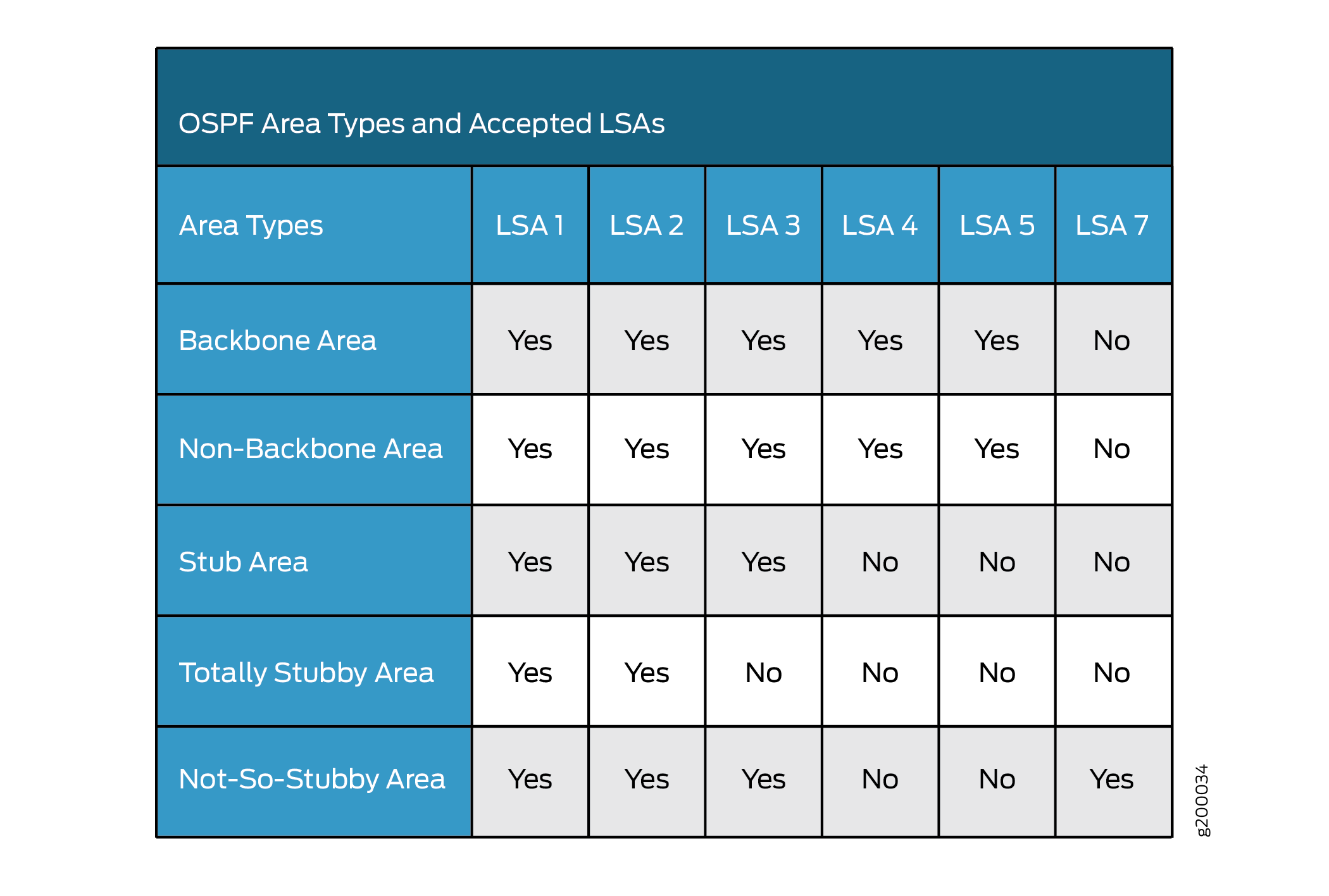
OSPF 区域类型和接受的 LSA
下表详细介绍了 OSPF 区域类型和接受的 LSA:
OSPF 指定路由器概述
由于链路状态通告 (LSA) 在网络中泛滥,具有许多路由设备并因此具有许多 OSPF 邻接的大型 LAN 可能会产生大量的控制数据包流量。为了缓解潜在的流量问题,OSPF 在所有多接入网络(广播和非广播多接入 [NBMA] 网络类型)上使用指定的路由器。路由设备不会向所有 OSPF 邻接方广播 LSA,而是将其 LSA 发送到指定的路由器。每个多接入网络都有一个指定的路由器,该路由器执行两个主要功能:
代表网络发起网络链路播发。
与网络上的所有路由设备建立邻接,从而参与链路状态数据库的同步。
在 LAN 中,指定路由器的选择在最初建立 OSPF 网络时进行。当第一个 OSPF 链路处于活动状态时,具有最高路由器标识符(由 路由器 ID 配置值定义,通常是路由设备的 IP 地址或环路地址)的路由设备将被选为指定的路由器。具有第二高路由器标识符的路由设备将被选为备份指定路由器。如果指定的路由器发生故障或失去连接,则备份指定路由器将承担其角色,并在 OSPF 网络中的所有路由器之间选择新的备份指定路由器。
OSPF 将路由器标识符用于两个主要目的:选择指定的路由器(除非您手动指定优先级值),以及识别数据包的来源路由设备。在指定路由器选择时,首先评估路由器优先级,然后选择优先级最高的路由设备指定路由器。如果路由器优先级一致,则会选择路由器标识符最高的路由设备(通常是路由设备的 IP 地址)作为指定路由器。如果未配置路由器标识符,则使用第一个要联机的接口的 IP 地址。这通常是环路接口。否则,将使用第一个具有 IP 地址的硬件接口。
每个逻辑 IP 网络或子网上必须至少有一台路由设备有资格成为 OSPFv2 的指定路由器。每个逻辑链路上至少有一个路由设备必须有资格成为 OSPFv3 的指定路由器。
默认情况下,路由设备的优先级为 128。优先级为 0 会将路由设备标记为不符合成为指定路由器的条件。优先级为 1 表示路由设备成为指定路由器的几率最小。优先级为 255 表示路由设备始终是指定的路由器。
示例:配置 OSPF 路由器标识符
此示例说明如何配置 OSPF 路由器标识符。
要求
开始之前:
确定路由设备上将参与 OSPF 的接口。您必须在网络中要传输 OSPF 流量的所有接口上启用 OSPF。
配置设备接口。请参阅 安全设备接口用户指南
概述
OSPF 使用路由器标识符来识别数据包的来源路由设备。Junos OS 根据以下一组规则选择路由器标识符:
默认情况下,Junos OS 会选择接口配置最低的物理 IP 地址作为路由器标识符。
如果配置了环路接口,则环路接口的 IP 地址将成为路由器标识符。
如果配置了多个环路接口,则最低的环路地址将成为路由器标识符。
如果使用
router-id address语句在层次结构级别下[edit routing-options]显式配置路由器标识符,则忽略以上三条规则。
1.此处描述的路由器标识符行为即使在和[edit logical-systems logical-system-name routing-instances routing-instance-name routing-options]层次结构级别下[edit routing-instances routing-instance-name routing-options]配置时也有效。
2. 如果在网络中修改了路由器标识符,则前一个路由器标识符播发的链路状态通告 (LSA) 将保留在 OSPF 数据库中,直到 LSA 重传间隔超时。因此,强烈建议您在 [edit routing-options] 层级下显式配置路由器标识符,以避免在环路接口上的接口地址发生变化时出现不可预测的行为。
在此示例中,您可以通过将 OSPF 路由器标识符的路由器 ID 值设置为设备的 IP 地址(即 192.0.2.24)来配置 OSPF 路由器标识符。
配置
CLI 快速配置
要快速配置 OSPF 路由器标识符,请复制以下命令,将其粘贴到文本文件中,删除所有换行符,更改详细信息,以便与网络配置匹配,将命令复制并粘贴到 [编辑] 层级的 CLI 中,然后从配置模式进入 commit 。
[edit]
set routing-options router-id 192.0.2.24
程序
分步过程
要配置 OSPF 路由器标识符,请执行以下作:
输入
[router-id]配置值,配置 OSPF 路由器标识符。[edit] user@host# set routing-options router-id 192.0.2.24
如果完成设备配置,请提交配置。
[edit]
user@host# commit
结果
输入 show routing-options router-id 命令以确认您的配置。如果输出未显示预期的配置,请重复此示例中的说明以更正配置。
user@host# show routing-options router-id
router-id 192.0.2.24;
验证
在路由设备上配置路由器 ID 并激活 OSPF 后,路由器 ID 将由多个 OSPF作模式命令引用,您可以使用这些命令对 OSPF 协议进行监控和故障排除。路由器 ID 字段在输出中清楚地标记。
示例:控制 OSPF 指定路由器选择
此示例说明如何控制 OSPF 指定的路由器选择。
要求
开始之前:
配置设备接口。请参阅 安全设备接口用户指南。
为 OSPF 网络中的设备配置路由器标识符。请参阅 示例:配置 OSPF 路由器标识符。
概述
此示例说明如何控制 OSPF 指定的路由器选择。在此示例中,您将 OSPF 接口设置为 ge-/0/0/1 ,将设备优先级设置为 200。优先级值越高,路由设备成为指定路由器的可能性就越大。
默认情况下,路由设备的优先级为 128。优先级为 0 会将路由设备标记为不符合成为指定路由器的条件。优先级为 1 表示路由设备成为指定路由器的几率最小。
配置
CLI 快速配置
要快速配置 OSPF 指定的路由器选择,请复制以下命令,将其粘贴到文本文件中,删除所有换行符,更改详细信息,以便与网络配置匹配,将命令复制并粘贴到 [编辑] 层级的 CLI 中,然后从配置模式进入 commit 。
[edit]
set protocols ospf area 0.0.0.3 interface ge-0/0/1 priority 200
程序
分步过程
要控制 OSPF 指定的路由器选择:
配置 OSPF 接口并指定设备优先级。
注意:要指定 OSPFv3 接口,请在
[edit protocols]层次结构级别包含ospf3语句。[edit] user@host# set protocols ospf area 0.0.0.3 interface ge-0/0/1 priority 200
如果完成设备配置,请提交配置。
[edit]
user@host# commit
结果
输入 show protocols ospf 命令以确认您的配置。如果输出未显示预期的配置,请重复此示例中的说明以更正配置。
user@host# show protocols ospf
area 0.0.0.3 {
    interface ge-0/0/1.0 {
        priority 200;
    }
}
要确认您的 OSPFv3 配置,请输入 show protocols ospf3 命令。
了解 OSPF 区域和主干区域
自治系统 (AS) 中的 OSPF 网络按管理方式分组为多个区域。AS 中的每个区域都像一个独立网络一样运行,并具有唯一的 32 位区域 ID,其功能类似于网络地址。在某个区域内,拓扑数据库仅包含有关该区域的信息,链路状态通告 (LSA) 仅泛洪到该区域内的节点,并且仅在该区域内计算路由。区域的拓扑对 AS 的其余部分是隐藏的,从而显著减少了 AS 中的路由流量。子网被划分为其他区域,这些区域相互连接,形成整个主网。完全位于某个区域内的路由设备称为内部路由器。内部路由器上的所有接口都直接连接到区域内的网络。
AS 的中心区域(称为主干区域)具有特殊功能,始终分配区域 ID 0.0.0.0。(在简单的单区域网络中,这也是该区域的 ID。地区 ID 是唯一的数字标识符,采用带点的十进制点表示法,但不是 IP 地址。区域 ID 只需要在 AS 中是唯一的。AS 中的所有其他网络或区域必须通过在多个区域具有接口的路由设备直接连接到主干区域。这些连接路由设备称为边界区域路由器 (ABR)。 图 1 显示了由两个 ABR 连接的三个区域的 OSPF 拓扑。
由于所有区域都与主干区域相邻,因此 OSPF 路由器会通过主干区域发送所有不发往其自身区域的流量。然后,骨干区域中的 ABR 负责通过相应的 ABR 将流量传输到目标区域。ABR 汇总每个区域的链路状态记录,并将目标地址摘要播发到邻近区域。播发包含每个目标所在区域的 ID,以便将数据包路由到相应的 ABR。例如,在 图 1 所示的 OSPF 区域中,从路由器 A 发送到路由器 C 的数据包会自动通过 ABR B 进行路由。
Junos OS 支持主动主干检测。实施主动主干检测以验证 ABR 是否已连接到主干。如果与主干区域的连接丢失,则不会播发路由设备的默认指标,从而有效地通过另一个与主干网有有效连接的 ABR 重新路由流量。主动骨干检测支持在没有活动骨干连接的情况下通过 ABR 进行中转。即使与主干网的连接断开,ABR 也会向其他路由设备通告它是 ABR,以便邻居可以考虑将其用于区域间路由。
OSPF 限制要求所有区域直接连接到骨干区域,以便正确路由数据包。默认情况下,所有数据包都首先路由到骨干区域。然后,发往主干区域以外的区域的数据包将被路由到相应的 ABR 和目标区域内的远程主机。
在具有许多区域的大型网络中,所有区域与主干区域之间的直接连接在物理上是困难的或是不可能的,您可以配置虚拟链路来连接不连续区域。虚拟链路使用包含两个或多个 ABR 的中转区域将网络流量从一个相邻区域传递到另一个相邻区域。例如, 图 2 显示了非连续区域和主干区域之间通过与两者相连的区域建立的虚拟链接。
 路的 OSPF 拓扑
在 图 2 所示的拓扑中,区域 0.0.0.3 和通过区域 0.0.0.2 的骨干区域之间建立了虚拟链路。发往其他区域的所有出站流量都通过区域 0.0.0.2 路由到主干区域,然后再路由到相应的 ABR。所有发往区域 0.0.0.3 的入站流量都将路由到骨干区域,然后通过区域 0.0.0.2。
示例:配置单区域 OSPF 网络
此示例说明如何配置单区域 OSPF 网络。
要求
开始之前:
配置设备接口。请参阅 安全设备接口用户指南。
为 OSPF 网络中的设备配置路由器标识符。请参阅 示例:配置 OSPF 路由器标识符。
概述
要在网络上激活 OSPF,必须在网络中要传输 OSPF 流量的所有接口上启用 OSPF 协议。要启用 OSPF,必须在 OSPF 区域内的设备上配置一个或多个接口。配置接口后,OSPF LSA 将在所有启用了 OSPF 的接口上传输,并在整个网络中共享网络拓扑。
在自治系统 (AS) 中,始终为主干区域分配区域 ID 0.0.0.0(在简单的单区域网络中,这也是区域的 ID)。区域 ID 是唯一的数字标识符,采用虚线十进制表示法。区域 ID 只需要在 AS 中是唯一的。AS 中的所有其他网络或区域必须通过在多个区域具有接口的区域边界路由器直接连接到主干区域。如果您的网络由多个区域组成,您还必须创建主干区域。在此示例中,您将创建主干网区域,并根据需要将接口(如 ge-0/0/0)添加到 OSPF 区域。
要在设备上使用 OSPF,必须配置至少一个 OSPF 区域,如 图 3 所示。
拓扑学
配置
CLI 快速配置
要快速配置单区域 OSPF 网络,请复制以下命令,将其粘贴到文本文件中,删除所有换行符,更改详细信息,以便与网络配置匹配,将命令复制并粘贴到 [编辑] 层次结构级别的 CLI 中,然后从配置模式进入 commit 。
[edit]
set protocols ospf area 0.0.0.0 interface ge-0/0/0
程序
分步过程
要配置单区域 OSPF 网络,请执行以下作:
通过指定区域 ID 和关联接口来配置单区域 OSPF 网络。
注意:对于单区域 OSPFv3 网络,请在
[edit protocols]层次结构级别包含ospf3语句。[edit] user@host# set protocols ospf area 0.0.0.0 interface ge-0/0/0
如果完成设备配置,请提交配置。
[edit]
user@host# commit
结果
输入 show protocols ospf 命令以确认您的配置。如果输出未显示预期的配置,请重复此示例中的说明以更正配置。
user@host# show protocols ospf
area 0.0.0.0 {
    interface ge-0/0/0.0;
}
要确认您的 OSPFv3 配置,请输入 show protocols ospf3 命令。
示例:配置多区域 OSPF 网络
此示例说明如何配置多区域 OSPF 网络。为了减少 OSPF 自治系统 (AS) 中设备的流量和拓扑维护,可以将支持 OSPF 的路由设备分组到多个区域中。
要求
开始之前:
配置设备接口。请参阅 安全设备接口用户指南。
为 OSPF 网络中的设备配置路由器标识符。请参阅 示例:配置 OSPF 路由器标识符。
控制 OSPF 指定的路由器选择。请参阅 示例:控制 OSPF 指定路由器选择
配置单区域 OSPF 网络。请参阅 示例:配置单区域 OSPF 网络。
概述
要在网络上激活 OSPF,必须在网络中要传输 OSPF 流量的所有接口上启用 OSPF 协议。要启用 OSPF,必须在 OSPF 区域内的设备上配置一个或多个接口。配置接口后,OSPF LSA 将在所有启用了 OSPF 的接口上传输,并在整个网络中共享网络拓扑。
每个 OSPF 区域都由配置了相同区域号的路由设备组成。 在图 4 中,路由器 B 位于 AS 的骨干区域。主干区域始终分配区域 ID 0.0.0.0。(所有区域 ID 在 AS 中必须是唯一的。)AS 中的所有其他网络或区域必须通过在多个区域具有接口的路由器直接连接到主干区域。在此示例中,这些区域边界路由器为 A、C、D 和 E。创建一个附加区域(区域 2)并为其分配唯一区域 ID 0.0.0.2,然后将接口 ge-0/0/0 添加到 OSPF 区域。
为了减少 OSPF AS 中设备的流量和拓扑维护,您可以将它们分组到多个区域中,如 图 4 所示。在此示例中,您将创建骨干区域,创建一个附加区域(区域 2)并为其分配唯一的区域 ID 0.0.0.2,并将设备 B 配置为区域边界路由器,其中接口 ge-0/0/0 参与 OSPF 区域 0,接口 ge-0/0/2 参与 OSPF 区域 2。
拓扑学
配置
程序
CLI 快速配置
要快速配置多区域 OSPF 网络,请复制以下命令,将其粘贴到文本文件中,删除所有换行符,更改详细信息,以便与网络配置匹配,将命令复制并粘贴到 [edit] 层次结构级别的 CLI 中,然后从配置模式进入 commit 。
设备 A
[edit]
set protocols ospf area 0.0.0.0 interface ge-0/0/0
set protocols ospf area 0.0.0.0 interface ge-0/0/1
设备 C
[edit]
set protocols ospf area 0.0.0.0 interface ge-0/0/0
设备 B
[edit]
set protocols ospf area 0.0.0.0 interface ge-0/0/0
set protocols ospf area 0.0.0.2 interface ge-0/0/2
设备 D
[edit]
set protocols ospf area 0.0.0.2 interface ge-0/0/0
set protocols ospf area 0.0.0.2 interface ge-0/0/2
设备 E
[edit]
set protocols ospf area 0.0.0.2 interface ge-0/0/2
分步过程
要配置多区域 OSPF 网络,请执行以下作:
配置主干区域。
注意:对于 OSPFv3 网络,请在
[edit protocols]层次结构级别包含ospf3语句。[edit] user@A# set protocols ospf area 0.0.0.0 interface ge-0/0/0 user@A# set protocols ospf area 0.0.0.0 interface ge-0/0/1
[edit]
user@C# set protocols ospf area 0.0.0.0 interface ge-0/0/0
[edit]
user@B# set protocols ospf area 0.0.0.0 interface ge-0/0/0
为 OSPF 网络配置一个附加区域。
注意:对于多区域 OSPFv3 网络,请在
[edit protocols]层次结构级别包含ospf3语句。[edit] user@host# set protocols ospf area 0.0.0.2 interface ge-0/0/0 user@D# set protocols ospf area 0.0.0.2 interface ge-0/0/2
[edit]
user@E# set protocols ospf area 0.0.0.2 interface ge-0/0/2
如果完成设备配置,请提交配置。
[edit]
user@host# commit
结果
输入 show protocols ospf 命令以确认您的配置。如果输出未显示预期的配置,请重复此示例中的说明以更正配置。
user@host# show protocols ospf
area 0.0.0.0 {
    interface ge-0/0/0.0;
    interface ge-0/0/1.0;
}
user@C# show protocols ospf
area 0.0.0.0 {
    interface ge-0/0/0.0;
}
user@B# show protocols ospf
area 0.0.0.0 {
    interface ge-0/0/0.0;
}
area 0.0.0.2 {
    interface ge-0/0/2.0;
}
user@D# show protocols ospf
area 0.0.0.2 {
    interface ge-0/0/0.0;
    interface ge-0/0/2.0;
}
user@E# show protocols ospf
area 0.0.0.2 {
    interface ge-0/0/2.0;
}
要确认您的 OSPFv3 配置,请输入 show protocols ospf3 命令。
了解 OSPF 的多区域邻接
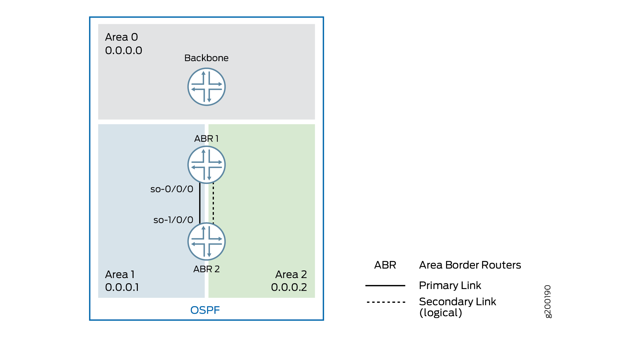
默认情况下,单个接口只能属于一个 OSPF 区域。但是,在某些情况下,您可能希望将接口配置为属于多个区域。这样一来,相应的链路就可以被视为多个区域中的区域内链路,并且优先于其他成本较高的区域内路径。例如,您可以将一个接口配置为属于多个区域,并在两个区域边界路由器 (ABR) 之间建立高速骨干链路,以便创建属于不同区域的多区域邻接。
在 Junos OS 9.2 及更高版本 中,您可以将 逻辑接口 配置为属于多个 OSPFv2 区域。Junos OS 9.4 版中引入了对 OSPFv3 的支持。如 RFC 5185 OSPF 多区域邻接中所定义,ABR 可通过同一逻辑接口建立属于不同区域的多个邻接。每个多区域邻接由连接到该链路的路由器在配置区域中宣布为点对点的无编号链路。对于每个区域,其中一个逻辑接口被视为主接口,为该区域配置的其余接口被指定为辅助接口。
任何未配置为某个区域的辅助接口的逻辑接口都将被视为该区域的主接口。逻辑接口只能配置为一个区域的主接口。对于为其配置接口的任何其他区域,必须将其配置为辅助接口。
示例:为 OSPF 配置多区域邻接
此示例说明如何为 OSPF 配置多区域邻接。
要求
开始之前,请规划您的多区域 OSPF 网络。请参阅 示例:配置多区域 OSPF 网络。
概述
默认情况下,单个接口只能属于一个 OSPF 区域。您可以将单个接口配置为属于多个 OSPF 区域。这样一来,相应的链路就可以被视为多个区域中的区域内链路,并且优先于其他成本较高的区域内路径。配置辅助接口时,请考虑以下事项:
对于 OSPFv2,您不能将点对多点和非广播多接入 (NBMA) 网络接口配置为辅助接口,因为辅助接口被视为点对点的无编号链路。
LAN 接口支持辅助接口(主接口可以是 LAN 接口,但任何辅助接口都被视为 LAN 上的点对点无编号链路)。在此方案中,必须确保 LAN 上只有两个路由设备,或者 LAN 上只有两个路由设备具有为特定 OSPF 区域配置的辅助接口。
由于辅助接口的目的是通告通过 OSPF 区域的拓扑路径,因此不能将辅助接口或具有一个或多个辅助接口的主接口配置为被动接口。无源接口会播发其地址,但不运行 OSPF 协议(不会形成邻接,也不会生成hello 数据包)。
任何未配置为某个区域的辅助接口的逻辑接口都将被视为该区域的主接口。逻辑接口只能配置为一个区域的主接口。对于为其配置接口的任何其他区域,必须将其配置为辅助接口。
不能使用语
interface all句配置secondary语句。您不能按辅助接口的 IP 地址来配置辅助接口。
 中的多区域邻接
在此示例中,您将接口配置为位于两个区域中,从而在两个 ABR 之间创建链路的多区域邻接:ABR R1 和 ABR R2。在每个 ABR 上,区域 0.0.0.1 包含主接口,是 ABR 之间的主链路,区域 0.0.0.2 包含辅助逻辑接口,您可以通过包含 secondary 语句来配置该接口。您可以在 ABR R1 上配置接口 so-0/0/0,在 ABR R2 上配置接口 so-1/0/0。
配置
CLI 快速配置
要为 OSPF 区域快速配置辅助逻辑接口,请复制以下命令,将其粘贴到文本文件中,删除所有换行符,更改详细信息,以便与网络配置匹配,将命令复制并粘贴到 [编辑] 层次结构级别的 CLI 中,然后从配置模式进入 commit 。
ABR R1 上的配置:
[edit]
set interfaces so-0/0/0 unit 0 family inet address 192.0.2.45/24
set routing-options router-id 10.255.0.1
set protocols ospf area 0.0.0.1 interface so-0/0/0
set protocols ospf area 0.0.0.2 interface so-0/0/0 secondary
ABR R2 上的配置:
[edit]
set interfaces so-1/0/0 unit 0 family inet address 192.0.2.37/24
set routing-options router-id 10.255.0.2
set protocols ospf area 0.0.0.1 interface so-1/0/0
set protocols ospf area 0.0.0.2 interface so-1/0/0 secondary
程序
分步过程
要配置辅助逻辑接口,请执行以下作:
配置设备接口。
注意:对于 OSPFv3,在每个接口上指定 inet6 地址族并包括 IPv6 地址。
[edit]
user@R1# set interfaces so-0/0/0 unit 0 family inet address 192.0.2.45/24
[edit]
user@R2# set interfaces so-1/0/0 unit 0 family inet address 192.0.2.37/24
配置路由器标识符。
[edit]
user@R1# set routing-options router-id 10.255.0.1
[edit]
user@R2# set routing-options router-id 10.255.0.2
在每个 ABR 上,为 OSPF 区域配置主接口。
注意:对于 OSPFv3,请在
[edit protocols]层次结构级别包含ospf3语句。[edit] user@R1# set protocols ospf area 0.0.0.1 interface so-0/0/0
[edit ]
user@R2# set protocols ospf area 0.0.0.1 interface so-1/0/0
在每个 ABR 上,为 OSPF 区域配置辅助接口。
[edit ]
user@R1# set protocols ospf area 0.0.0.2 so-0/0/0 secondary
[edit ]
user@R2# set protocols ospf area 0.0.0.2 so-1/0/0 secondary
如果完成设备配置,请提交配置。
[edit protocols ospf area 0.0.0.1 ]
user@host# commit
结果
输入show interfacesshow routing-optionsshow protocols ospf、和命令,以确认您的配置。如果输出未显示预期的配置,请重复此示例中的说明以更正配置。
ABR R1 上的配置:
user@R1# show interfaces
so-0/0/0 {
    unit 0 {
        family inet {
            address 192.0.2.45/24;
        }
    }
}
user@R1# show routing-options
router-id 10.255.0.1;
user@R1# show protocols ospf
area 0.0.0.1 {
    interface so-0/0/0.0;
}
area 0.0.0.2 {
    interface so-0/0/0.0 {
        secondary;
    }
}
ABR R2 上的配置:
user@R2# show interfaces
so-0/0/0 {
    unit 0 {
        family inet {
            address 192.0.2.37/24;
        }
    }
}
user@R2# show routing-options
router-id 10.255.0.2;
user@R2# show protocols ospf
area 0.0.0.1 {
    interface so-1/0/0.0;
}
area 0.0.0.2 {
    interface so-1/0/0.0 {
        secondary;
    }
}
验证
确认配置工作正常。
验证辅助接口
目的
验证配置区域是否显示了辅助接口。如果接口配置为辅助接口,则显示辅助字段。输出还可能显示在多个区域中列出的相同接口。
行动
在作模式下, show ospf interface detail 输入适用于 OSPFv2 的命令,然后 show ospf3 interface detail 输入适用于 OSPFv3 的命令。
验证该区域中的接口
目的
验证为指定区域配置的接口。
行动
在作模式下, show ospf interface area area-id 输入 OSPFv2 命令,然后 show ospf3 interface area area-id 输入 OSPFv3 命令。
了解 OSPFv3 的多区域邻接
区域是 OSPFv3 域中在管理上组合在一起的一组网络和主机。默认情况下,单个接口只能属于一个 OSPFv3 区域。但是,在某些情况下,您可能需要将接口配置为属于多个区域,以避免次优路由。这样一来,相应的链路就可以被视为多个区域中的区域内链路,并且比成本较高的区域内链路更优先。
在 Junos OS 9.2 及更高版本 中,您可以将接口配置为属于多个 OSPFv2 区域。Junos OS 9.4 版中引入了对 OSPFv3 的支持。如 RFC 5185 OSPF 多区域邻接中所定义,ABR 可通过同一 逻辑接口建立属于不同区域的多个邻接。每个多区域邻接由连接到该链路的路由器在配置区域中宣布为点对点的无编号链路。
一个接口主要被视为在一个区域中。在其他区域配置相同的接口时,该接口会被视为在其他区域中的次要接口。您可以通过在[edit protocols ospf3 area area-number interface interface-name]层次结构级别上包含secondary语句来指定辅助区域。
示例:为 OSPFv3 配置多区域邻接
此示例说明如何为 OSPFv3 配置多区域邻接。
要求
配置此示例之前,不需要除设备初始化之外的特殊配置。
概述
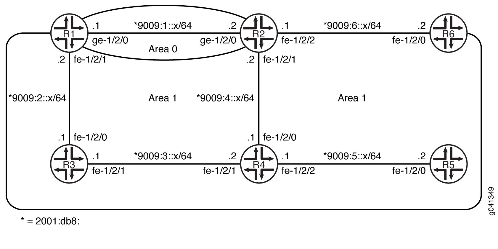
OSPFv3 区域内路径优先于区域间路径。在此示例中,设备 R1 和设备 R2 是区域边界路由器 (ABR),其接口分别位于区域 0 和区域 1。设备 R1 和 R2 之间的链路位于区域 0 中,是高速链路。区域 1 中的链路速度较低。
如果要通过高速链路在设备 R1 和设备 R2 之间转发区域 1 的部分流量,则实现此目标的一种方法是使高速链路成为多区域邻接,以便链路同时属于区域 0 和区域 1。
如果设备 R1 和设备 R2 之间的高速链路仅保留在区域 1 中,则设备 R1 将始终通过低速链路通过区域 1 将流量路由到设备 R4 和设备 R5。设备 R1 还使用通过设备 R3 的区域内区域 1 路径到达设备 R2 下游的区域 1 目标。
显然,这种情况会导致次优路由。
如果不将设备 R1 和设备 R2 之间的链路移动到区域 1,则无法使用 OSPF 虚拟链路来解决此问题。如果物理链路属于网络的骨干拓扑,则可能不希望执行此作。
RFC 5185 OSPF 多区域邻 接中描述的 OSPF/OSPFv3 协议扩展允许设备 R1 和设备 R2 之间的链路同时属于主干区域和区域 1,从而解决了这个问题。
要创建多区域邻接,请将接口配置为位于两个区域中,设备 R1 上的 ge-1/2/0 配置在区域 0 和区域 1 中,设备 R2 上的 ge-1/2/0 同时配置在区域 0 和区域 1 中。在设备 R1 和设备 R2 上,区域 0 包含主接口,并且是设备之间的主链路。区域 1 包含辅助逻辑接口,您可以通过包含 secondary 语句来配置该接口。
CLI 快速配置 显示了 图 6 中所有设备的配置。 #d19e74__d19e376 部分介绍了设备 R1 和设备 R2 上的步骤。
配置
程序
CLI 快速配置
要快速配置此示例,请复制以下命令,将其粘贴到文本文件中,删除所有换行符,更改详细信息,以便与网络配置匹配,然后将命令复制并粘贴到层 [edit] 级的 CLI 中。
设备 R1
set interfaces ge-1/2/0 unit 0 family inet6 address 2001:db8:9009:1::1/64
set interfaces fe-1/2/1 unit 0 family inet6 address 2001:db8:9009:2::2/64
set interfaces lo0 unit 0 family inet address 10.1.1.1/32
set interfaces lo0 unit 0 family inet6 address 2001:db8:9009::1/128
set protocols ospf3 area 0.0.0.0 interface ge-1/2/0.0
set protocols ospf3 area 0.0.0.0 interface lo0.0 passive
set protocols ospf3 area 0.0.0.1 interface fe-1/2/1.0
set protocols ospf3 area 0.0.0.1 interface ge-1/2/0.0 secondary
设备 R2
set interfaces ge-1/2/0 unit 0 family inet6 address 2001:db8:9009:1::1/64
set interfaces fe-1/2/1 unit 0 family inet6 address 2001:db8:9009:4::1/64
set interfaces fe-1/2/2 unit 0 family inet6 address 2001:db8:9009:6::1/64
set interfaces lo0 unit 0 family inet address 10.2.2.2/32
set interfaces lo0 unit 0 family inet6 address 2001:db9:9001::2/128
set protocols ospf3 area 0.0.0.0 interface ge-1/2/0.0
set protocols ospf3 area 0.0.0.0 interface lo0.0 passive
set protocols ospf3 area 0.0.0.1 interface fe-1/2/2.0
set protocols ospf3 area 0.0.0.1 interface fe-1/2/1.0
set protocols ospf3 area 0.0.0.1 interface ge-1/2/0.0 secondary
设备 R3
set interfaces fe-1/2/0 unit 0 family inet6 address 2001:db8:9009:2::1/64
set interfaces fe-1/2/1 unit 0 family inet6 address 2001:db8:9009:3::1/64
set interfaces lo0 unit 0 family inet address 10.3.3.3/32
set interfaces lo0 unit 0 family inet6 address 2001:db8:9009::3/128
set protocols ospf3 area 0.0.0.1 interface fe-1/2/0.0
set protocols ospf3 area 0.0.0.1 interface lo0.0 passive
set protocols ospf3 area 0.0.0.1 interface fe-1/2/1.0
设备 R4
set interfaces fe-1/2/0 unit 0 family inet6 address 2001:db8:9009:3::2/64
set interfaces fe-1/2/1 unit 0 family inet6 address 2001:db8:9009:4::1/64
set interfaces fe-1/2/2 unit 0 family inet6 address 2001:db8:9009:5::1/64
set interfaces lo0 unit 0 family inet address 10.4.4.4/32
set interfaces lo0 unit 0 family inet6 address 2001:db8:9009::4/128
set protocols ospf3 area 0.0.0.1 interface fe-1/2/0.0
set protocols ospf3 area 0.0.0.1 interface fe-1/2/1.0
set protocols ospf3 area 0.0.0.1 interface lo0.0 passive
set protocols ospf3 area 0.0.0.1 interface fe-1/2/2.0
设备 R5
set interfaces fe-1/2/0 unit 0 family inet6 address 2001:db8:9009:5::2/64
set interfaces lo0 unit 0 family inet address 10.5.5.5/32
set interfaces lo0 unit 0 family inet6 address 2001:db8:9009::5/128
set protocols ospf3 area 0.0.0.1 interface lo0.0 passive
set protocols ospf3 area 0.0.0.1 interface fe-1/2/0.0
设备 R6
set interfaces fe-1/2/0 unit 0 family inet6 address 2001:db8:9009:6::2/64
set interfaces lo0 unit 0 family inet address 10.6.6.6/32
set interfaces lo0 unit 0 family inet6 address 2001:db8:9009::6/128
set protocols ospf3 area 0.0.0.1 interface lo0.0 passive
set protocols ospf3 area 0.0.0.1 interface fe-1/2/0.0
分步过程
下面的示例要求您在各个配置层级中进行导航。有关 CLI 导航的信息,请参阅 CLI 用户指南中的在配置模式下使用 CLI 编辑器。
要配置设备 R1,请执行以下作:
-
配置接口。
[edit interfaces]
user@R1# set ge-1/2/0 unit 0 family inet6 address 2001:db8:9009:1::1/64
user@R1# set fe-1/2/1 unit 0 family inet6 address 2001:db8:9009:2::2/64
user@R1# set lo0 unit 0 family inet address 10.1.1.1/32
user@R1# set lo0 unit 0 family inet6 address 2001:db8:9009::1/128
-
在区域 0 中的接口上启用 OSPFv3。
[edit protocols ospf3 area 0.0.0.0]
user@R1# set interface ge-1/2/0.0
user@R1# set interface lo0.0 passive
-
在区域 1 中的接口上启用 OSPFv3。
[edit protocols ospf3 area 0.0.0.1]
user@R1# set interface fe-1/2/1.0
user@R1# set interface ge-1/2/0.0 secondary
分步过程
下面的示例要求您在各个配置层级中进行导航。有关 CLI 导航的信息,请参阅 CLI 用户指南中的在配置模式下使用 CLI 编辑器。
要配置设备 R2,请执行以下作:
-
配置接口。
[edit interfaces]
user@R2# set ge-1/2/0 unit 0 family inet6 address 2001:db8:9009:1::2/64
user@R2# set fe-1/2/1 unit 0 family inet6 address 2001:db8:9009:4::2/64
user@R2# set fe-1/2/2 unit 0 family inet6 address 2001:db8:9009:6::2/64
user@R2# set lo0 unit 0 family inet address 10.2.2.2/32
user@R2# set lo0 unit 0 family inet6 address 2001:db8:9009::2/128
-
在区域 0 中的接口上启用 OSPFv3。
[edit protocols ospf3 area 0.0.0.0]
user@R2# set interface ge-1/2/0.0
user@R2# set interface lo0.0 passive
-
在区域 1 中的接口上启用 OSPFv3。
[edit protocols ospf3 area 0.0.0.1]
user@R2# set interface fe-1/2/2.0
user@R2# set interface fe-1/2/1.0
user@R2# set interface ge-1/2/0.0 secondary
结果
在配置模式下,输入 show interfaces 和 show protocols 命令,以确认您的配置。如果输出未显示预期的配置,请重复此示例中的说明以更正配置。
设备 R1
user@R1# show interfaces
ge-1/2/0 {
    unit 0 {
        family inet6 {
            address 2001:db8:9009:1::1/64/64;
        }
    }
}
fe-1/2/1 {
    unit 0 {
        family inet6 {
            address 2001:db8:9009:2::2/64;
        }
    }
}
lo0 {
    unit 0 {
        family inet {
            address 10.1.1.1/32;
        }
        family inet6 {
            address 2001:db8:9009::1/128;
        }
    }
}
user@R1# show protocols
ospf3 {
    area 0.0.0.0 {
        interface ge-1/2/0.0;
        interface lo0.0 {
            passive;
        }
    }
    area 0.0.0.1 {
        interface fe-1/2/1.0;
        interface ge-1/2/0.0 {
            secondary;
        }
    }
}
设备 R2
user@R2# show interfaces
ge-1/2/0 {
    unit 0 {
        family inet6 {
            address 2001:db8:9009:1::2/64;
        }
    }
}
fe-1/2/1 {
    unit 0 {
        family inet6 {
            address 2001:db8:9009:4::1/64;
        }
    }
}
fe-1/2/2 {
    unit 0 {
        family inet6 {
            address 2001:db8:9009:6::2/64;
        }
    }
}
lo0 {
    unit 0 {
        family inet {
            address 10.2.2.2/32;
        }
        family inet6 {
            address 2001:db8:9009::2/128;
        }
    }
}
user@R2# show protocols
ospf3 {
    area 0.0.0.0 {
        interface ge-1/2/0.0;
        interface lo0.0 {
            passive;
        }
    }
    area 0.0.0.1 {
        interface fe-1/2/2.0;
        interface fe-1/2/1.0;
        interface ge-1/2/0.0 {
            secondary;
        }
    }
}
如果完成设备配置,请从配置模式输入 commit 。
验证
确认配置工作正常。
验证流量
目的
验证流量是否使用设备 R1 和设备 R2 之间的高速链路到达区域 1 中的目标。
行动
在设备 R1 的作模式下,使用 traceroute 命令检查流向设备 R5 和设备 R6 的流量。
user@R1> traceroute 2001:db8:9009::6
traceroute6 to 2001:db8:9009::6 (2001:db8:9009::6 ) from 2001:db8:9009:1::1 , 64 hops max, 12 byte packets
 1  2001:db8:9009:1::2 (2001:db8:9009:1::2 )  1.361 ms  1.166 ms  1.117 ms
 2  2001:db8:9009::6 (2001:db8:9009::6 )  1.578 ms  1.484 ms  1.488 ms
user@R1> traceroute 2001:db8:9009::5
traceroute6 to 2001:db8:9009::5 (2001:db8:9009::5) from 2001:db8:9009:1::1, 64 hops max, 12 byte packets
 1  2001:db8:9009:1::2 (2001:db8:9009:1::2)  1.312 ms  1.472 ms  1.132 ms
 2  2001:db8:9009:4::1 (2001:db8:9009:4::1)  1.137 ms  1.174 ms  1.126 ms
 3  2001:db8:9009::5 (5::5)  1.591 ms  1.445 ms  1.441 ms
意义
traceroute 输出显示流量使用设备 R1 和设备 R2 之间的 9009:1:: 链路。
验证删除多区域邻接时流量是否发生变化
目的
在未配置多区域邻接的情况下验证结果。
行动
-
停用 R1 和 R2 上区域 1 中的骨干链路接口。
user@R1# deactivate protocols ospf3 area 0.0.0.1 interface ge-1/2/0.0
user@R1# commit
user@R2# deactivate protocols ospf3 area 0.0.0.1 interface ge-1/2/0.0
user@R2# commit
-
在设备 R1 的作模式下,使用
traceroute命令检查流向设备 R5 和设备 R6 的流量。user@R1> traceroute 2001:db8:9009::6 traceroute6 to 2001:db8:9009::6 (2001:db8:9009::6) from 2001:db8:9009:2::2, 64 hops max, 12 byte packets 1 2001:db8:9009:2::1 (2001:db8:9009:2::1) 1.314 ms 8.523 ms 8.310 ms 2 2001:db8:9009:3::2 (2001:db8:9009:3::2) 1.166 ms 1.162 ms 1.172 ms 3 2001:db8:9009:4::1 (2001:db8:9009:4::1) 1.386 ms 1.182 ms 1.138 ms 4 2001:db8:9009::6 (2001:db8:9009::6) 1.605 ms 1.469 ms 1.438 ms
user@R1> traceroute 2001:db8:9009::5
traceroute6 to 2001:db8:9009::5 (2001:db8:9009::5) from 2001:db8:9009:2::2, 64 hops max, 12 byte packets
 1  2001:db8:9009:2::1 (2001:db8:9009:2::1)  1.365 ms  1.174 ms  1.133 ms
 2  2001:db8:9009:3::2 (2001:db8:9009:2::1)  1.157 ms  1.198 ms  1.138 ms
 3  2001:db8:9009:5::5 (2001:db8:9009:5::5)  1.584 ms  1.461 ms  1.443 ms
意义
如果没有多区域邻接,输出显示次优路由,流量路径会通过区域 1 的低速链路。
了解 OSPF 剩余区域、完全剩余区域和不那么剩余区域
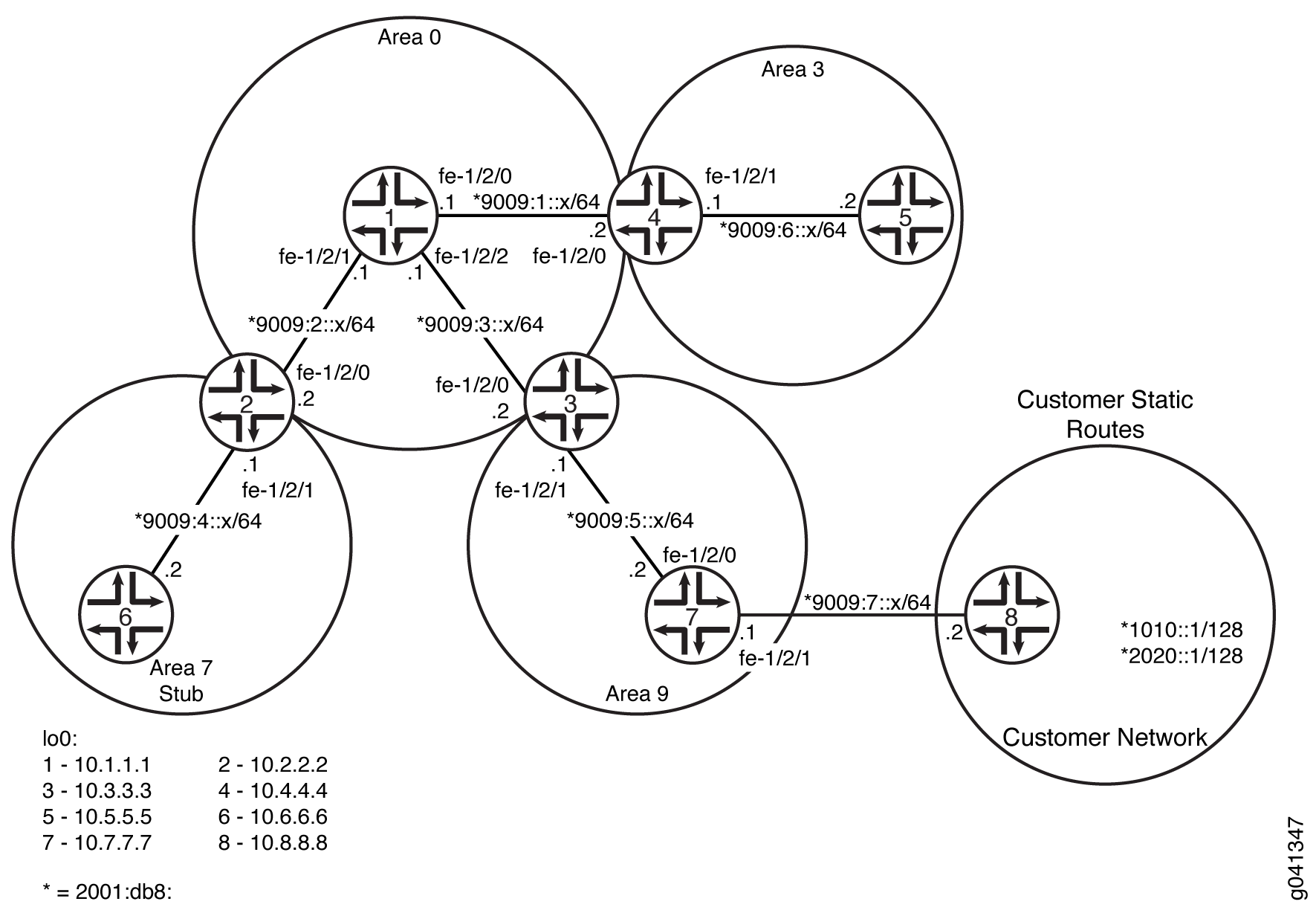
图 7 显示了一个自治系统 (AS),许多外部路由都通过该系统进行通告。如果外部路由在拓扑数据库中占有很大比重,则可以在没有网络外部链接的区域中抑制播发。通过这样做,可以减少节点用于维护拓扑数据库的内存量,并将其释放用于其他用途。
 的 OSPF AS 网络
要控制外部路由播发到某个区域,OSPF 使用剩余区域。通过将区域边界路由器 (ABR) 接口指定为剩余接口,可以抑制通过 ABR 的外部路由播发。相反,ABR 会(通过自身)播发默认路由来代替外部路由,并生成网络摘要(类型 3)链路状态通告 (LSA)。发往外部路由的数据包会自动发送到 ABR,后者充当出站流量的网关并适当地路由流量。
您必须将 ABR 显式配置为在连接到存根或不完全剩余区域 (NSSA) 时生成默认路由。要将具有指定指标值的默认路由注入到区域中,必须配置 default-metric 该选项并指定指标值。
例如, 图 7 中的区域 0.0.0.3 没有直接连接到外部网络。所有出站流量都通过 ABR 路由到主干网,然后再路由到目标地址。通过将区域 0.0.0.3 指定为剩余区域,您可以通过将路由条目限制为仅区域内部的路由来减小该区域的拓扑数据库的大小。
仅允许区域内部的路由并限制 3 类 LSA 进入剩余区域的剩余区域通常称为完全剩余区域。您可以通过将 ABR 配置为仅播发并允许默认路由进入该区域,将区域 0.0.0.3 转换为完全剩余的区域。到其他地区的外部路线和目的地不再汇总或允许进入完全剩余的区域。
如果错误地配置了完全剩余的区域,则可能会遇到网络连接问题。在配置完全剩余区域之前,您应该具备 OSPF 的高级知识并了解您的网络环境。
与 图 7 中的区域 0.0.0.3 类似,区域 0.0.0.4 没有外部连接。但是,区域 0.0.0.4 具有非内部 OSPF 路由的静态客户路由。您可以将外部路由播发限制到该区域,并通过将该区域指定为 NSSA 来播发静态客户路由。在 NSSA 中,AS 边界路由器生成 NSSA 外部(类型 7)LSA,并将其泛洪到 NSSA 中,并在其中容纳这些 LSA。类型 7 LSA 允许 NSSA 支持 AS 边界路由器的存在及其相应的外部路由信息。ABR 将 7 类 LSA 转换为 AS 外部(5 类)LSA 并将它们泄漏到其他区域,但来自其他区域的外部路由不会在 NSSA 内公布。
示例:配置 OSPF 剩余区域和完全剩余区域
此示例说明如何配置 OSPF 剩余区域和完全剩余区域,以控制外部路由向某个区域播发。
要求
开始之前:
配置设备接口。请参阅 安全设备接口用户指南。
为 OSPF 网络中的设备配置路由器标识符。请参阅 示例:配置 OSPF 路由器标识符。
控制 OSPF 指定的路由器选择。请参阅 示例:控制 OSPF 指定路由器选择
配置多区域 OSPF 网络。请参阅 示例:配置多区域 OSPF 网络。
概述
主干区域( 图 8 中的 0)具有特殊功能,始终分配区域 ID 0.0.0.0。区域 ID 是唯一的数字标识符,采用虚线十进制表示法。区域 ID 只需要在自治系统 (AS) 中是唯一的。AS 中的所有其他网络或区域(例如 3、7 和 9)必须通过在多个区域具有接口的区域边界路由器 (ABR) 直接连接到主干区域。
剩余区域是指 OSPF 不会通过或进入 AS 外部链路状态通告(类型 5 LSA)的区域。当大部分拓扑数据库由 AS 外部播发组成,并且您希望将剩余区域中内部路由器上的拓扑数据库大小降至最低时,您可以创建剩余区域。
以下限制适用于存根区域:
不能通过存根区域创建虚拟链接。
剩余区域不能包含 AS 边界路由器。
不能将主干网配置为剩余区域。
不能将区域同时配置为剩余区域和非剩余区域 (NSSA)。
在此示例中,您将区域 7(区域 ID 0.0.0.7)中的每个路由设备配置为剩余路由器,并在 ABR 上进行一些其他设置:
stub- 指定此区域成为剩余区域,并且不会被 5 类 LSA 淹没。您必须在区域 7 中的所有路由设备上包含该stub语句,因为此区域没有外部连接。default-metric- 配置 ABR 以在存根区域中生成具有指定度量的默认路由。此默认路由允许数据包从剩余区域转发到外部目的地。只能在 ABR 上配置此选项。当连接到存根时,ABR 不会自动生成默认路由。您必须显式配置此选项才能生成默认路由。no-summaries—(可选)通过将剩余区域转换为完全剩余区域,防止 ABR 将汇总路由播发到剩余区域。如果与default-metric语句一起配置,则完全剩余区域仅允许区域内部的路由,并将默认路由播发到该区域中。到其他地区的外部路线和目的地不再汇总或允许进入完全剩余的区域。只有 ABR 需要此额外配置,因为它是完全剩余区域内唯一可创建 3 类 LSA 的路由设备,用于从区域外部接收和发送流量。
在 Junos OS 8.5 及更高版本中,以下情况适用:
未配置为运行 OSPF 的路由器标识符接口不再在 OSPF LSA 中作为剩余网络播发。
如果环路接口配置的前缀长度不是 32,OSPF 会将前缀长度为 32 的本地路由作为短链路通告。与早期版本一样,OSPF 还会使用配置的掩码长度播发直接路由。
 的 OSPF 网络拓扑
拓扑学
配置
CLI 快速配置
要快速配置 OSPF 剩余区域,请复制以下命令并将其粘贴到 CLI 中。您必须配置属于存根区域的所有路由设备。
[edit]
set protocols ospf area 07 stub
要快速配置 ABR 以将默认路由注入到该区域,请复制以下命令并将其粘贴到 CLI 中。只能在 ABR 上应用此配置。
[edit]
set protocols ospf area 07 stub default-metric 10
(选答)要快速配置 ABR 以限制所有摘要播发,并且仅允许内部路由和默认路由播发进入该区域,请复制以下命令并将其粘贴到 CLI 中。只能在 ABR 上应用此配置。
[edit]
set protocols ospf area 0.0.0.7 stub no-summaries
程序
分步过程
要配置 OSPF 剩余区域,请执行以下作:
在该区域的所有路由设备上,配置 OSPF 剩余区域。
注意:要指定 OSPFv3 存根区域,请在
[edit protocols]层次结构级别包含ospf3语句。[edit] user@host# set protocols ospf area 0.0.0.7 stub
在 ABR 上,将默认路由注入到该区域。
[edit] user@host# set protocols ospf area 0.0.0.7 stub default-metric 10
(选答)在 ABR 上,限制汇总 LSA 进入该区域。此步骤将剩余区域转换为完全剩余区域。
[edit]
user@host# set protocols ospf area 0.0.0.7 stub no-summaries
如果完成设备配置,请提交配置。
[edit]
user@host# commit
结果
输入 show protocols ospf 命令以确认您的配置。如果输出未显示预期的配置,请重复此示例中的说明以更正配置。
所有路由设备上的配置:
user@host# show protocols ospf
area 0.0.0.7 {
    stub;
}
ABR 上的配置(输出还包括可选设置):
user@host# show protocols ospf
area 0.0.0.7 {
    stub default-metric 10 no-summaries;
}
要确认您的 OSPFv3 配置,请输入 show protocols ospf3 命令。
验证
确认配置工作正常。
验证该区域中的接口
目的
验证是否已为相应的区域配置了 OSPF 接口。确认输出包含存根作为 OSPF 区域的类型。
行动
在作模式下, show ospf interface detail 输入适用于 OSPFv2 的命令,然后 show ospf3 interface detail 输入适用于 OSPFv3 的命令。
示例:配置 OSPF 不完全剩余区域
此示例说明如何配置 OSPF 不完全剩余区域 (NSSA) 以控制外部路由到某个区域的播发。
要求
开始之前:
配置设备接口。请参阅 安全设备接口用户指南。
为 OSPF 网络中的设备配置路由器标识符。请参阅 示例:配置 OSPF 路由器标识符。
控制 OSPF 指定的路由器选择。请参阅 示例:控制 OSPF 指定路由器选择
配置多区域 OSPF 网络。请参阅 示例:配置多区域 OSPF 网络。
概述
骨干区域( 图 9 中的 0)具有特殊功能,始终分配区域 ID 0.0.0.0。区域 ID 是唯一的数字标识符,采用虚线十进制表示法。区域 ID 只需要在 AS 中是唯一的。AS 中的所有其他网络或区域(例如 3、7 和 9)必须通过在多个区域具有接口的 ABR 直接连接到主干区域。
OSPF 剩余区域没有外部路由,因此您无法将路由从其他协议重新分配到剩余区域。OSPF NSSA 允许外部路由在区域内泛滥。
此外,您可能还会遇到不需要将 7 类 LSA 导出到 NSSA 的情况。当 AS 边界路由器也是连接了 NSSA 的 ABR 时,默认情况下,类型 7 LSA 会导出到 NSSA 中。如果 ABR 连接到多个 NSSA,则默认情况下会将单独的 7 类 LSA 导出到每个 NSSA 中。在路由重新分配期间,此路由设备会同时生成 5 类 LSA 和 7 类 LSA。您可以禁止将 7 类 LSA 导出到 NSSA。
以下限制适用于 NSSA:不能将区域同时配置为存根区域和 NSSA。
使用以下设置配置区域 9(区域 ID 0.0.0.9)中的每个路由设备:
nssa- 指定 OSPF NSSA。您必须在区域 9 中的所有路由设备上包含该nssa语句,因为此区域只有与静态路由的外部连接。
您还可以使用以下附加设置在区域 9 中配置 ABR:
no-summaries— 防止 ABR 播发进入 NSSA 的汇总路由。如果与语default-metric句一起配置,则 NSSA 仅允许区域内部的路由,并将默认路由播发到该区域。通往其他地区的外部路线和目的地不再汇总或允许进入 NSSA。只有 ABR 需要这种额外配置,因为它是 NSSA 中唯一创建用于从区域外部接收和发送流量的 3 类 LSA 的路由设备。default-lsa- 配置 ABR 以生成进入 NSSA 的默认路由。在此示例中,您将配置以下内容:default-metric- 指定 ABR 在 NSSA 中生成具有指定指标的默认路由。此默认路由允许将数据包从 NSSA 转发到外部目的地。只能在 ABR 上配置此选项。当连接到 NSSA 时,ABR 不会自动生成默认路由。您必须为 ABR 显式配置此选项才能生成默认路由。metric-type—(可选)指定默认 LSA 的外部度量类型,可以是类型 1 或类型 2。当 OSPF 从外部 AS 导出路由信息时,它会在路由中包含成本或外部指标。这两个指标之间的区别在于 OSPF 计算路由成本的方式。类型 1 外部指标等同于链路状态指标,其中成本等于内部成本加上外部成本之和。类型 2 外部指标仅使用 AS 边界路由器分配的外部成本。默认情况下,OSPF 使用 2 类外部指标。type-7—(可选)如果配置了no-summaries语句,则将类型 7 默认 LSA 泛洪到 NSSA 中。默认情况下,配置语句时no-summaries,Junos OS 5.0 及更高版本的 NSSA 中会注入 3 类 LSA。要支持向后兼容早期 Junos OS 版本,请包含type-7语句。
第二个示例还展示了通过在同时执行 ABR 和 AS 边界路由器功能的路由设备上包含 no-nssa-abr 语句来禁用将 7 类 LSA 导出到 NSSA 所需的可选配置。
的 OSPF 网络拓扑
拓扑学
配置
将路由设备配置为参与不完全剩余区域
CLI 快速配置
要快速配置 OSPF NSSA,请复制以下命令并将其粘贴到 CLI 中。您必须配置属于 NSSA 的所有路由设备。
[edit]
set protocols ospf area 0.0.0.9 nssa
要快速配置参与 OSPF NSSA 的 ABR,请将以下命令复制粘贴到 CLI 中。
[edit]
set protocols ospf area 0.0.0.9 nssa default-lsa default-metric 10
set protocols ospf area 0.0.0.9 nssa default-lsa metric-type 1
set protocols ospf area 0.0.0.9 nssa default-lsa type-7
set protocols ospf area 0.0.0.9 nssa no-summaries
分步过程
要配置 OSPF NSSA,请执行以下作:
在该区域的所有路由设备上,配置 OSPF NSSA。
注意:要指定 OSPFv3 NSSA 区域,请在
[edit protocols]层次结构级别包含ospf3语句。[edit] user@host# set protocols ospf area 0.0.0.9 nssa
在 ABR 上,进入 OSPF 配置模式并指定已创建的 NSSA 区域 0.0.0.9。
[edit ]
user@host# edit protocols ospf area 0.0.0.9 nssa
在 ABR 上,将默认路由注入到该区域。
[edit protocols ospf area 0.0.0.9 nssa]
user@host# set default-lsa default-metric 10
(选答)在 ABR 上,指定默认路由的外部指标类型。
[edit protocols ospf area 0.0.0.9 nssa]
user@host# set default-lsa metric-type 1
(选答)在 ABR 上,指定 7 类 LSA 的泛洪。
[edit protocols ospf area 0.0.0.9 nssa]
user@host# set default-lsa type-7
在 ABR 上,限制汇总 LSA 进入该区域。
[edit protocols ospf area 0.0.0.9 nssa]
user@host# set no-summaries
如果完成设备配置,请提交配置。
[edit protocols ospf area 0.0.0.9 nssa]
user@host# commit
结果
输入 show protocols ospf 命令以确认您的配置。如果输出未显示预期的配置,请重复此示例中的说明以更正配置。
区域内所有路由设备的配置:
user@host# show protocols ospf
area 0.0.0.9 {
    nssa;
}
ABR 上的配置。输出还包括可选的 metric-type 和 type-7 语句。
user@host# show protocols ospf
    area 0.0.0.9 {
    nssa {
        default-lsa {
            default-metric 10;
            metric-type 1;
            type-7;
        }
        no-summaries;
    }
}
要确认您的 OSPFv3 配置,请输入 show protocols ospf3 命令。
禁止将 7 类链路状态播发导出到不那么剩余的区域
CLI 快速配置
要快速禁用将 7 类 LSA 导出到 NSSA,请复制以下命令,将其粘贴到文本文件中,删除所有换行符,更改任何必要的详细信息以匹配您的网络配置,将命令复制并粘贴到 [编辑] 层次结构级别的 CLI 中,然后从配置模式进入 commit 。您可以在同样是连接了 NSSA 区域的 ABR 的 AS 边界路由器上配置此设置。
[edit]
set protocols ospf no-nssa-abr
分步过程
如果您的 AS 边界路由器也是连接了 NSSA 区域的 ABR,则可以配置此设置。
禁止将 7 类 LSA 导出到 NSSA。
注意:要指定 OSPFv3,请在
[edit protocols]层次结构级别包含语ospf3句。[edit] user@host# set protocols ospf no-nssa-abr
如果完成设备配置,请提交配置。
[edit]
user@host# commit
结果
输入 show protocols ospf 命令以确认您的配置。如果输出未显示预期的配置,请重复此示例中的说明以更正配置。
user@host# show protocols ospf
no-nssa-abr;
要确认您的 OSPFv3 配置,请输入 show protocols ospf3 命令。
验证
确认配置工作正常。
验证该区域中的接口
目的
验证是否已为相应的区域配置了 OSPF 接口。确认输出包含存根 NSSA 作为 OSPF 区域的类型。
行动
在作模式下, show ospf interface detail 输入适用于 OSPFv2 的命令,然后 show ospf3 interface detail 输入适用于 OSPFv3 的命令。
验证 OSPF 区域的类型
目的
验证 OSPF 区域是否为剩余区域。确认输出显示 Not so Stubby Stub 作为 Stub 类型。
行动
在作模式下, show ospf overview 输入适用于 OSPFv2 的命令,然后 show ospf3 overview 输入适用于 OSPFv3 的命令。
了解 OSPFv3 存根和完全剩余区域
IPv6 网络的 Junos OS OSPFv3 配置与 OSPFv2 配置相同。您可以使用 set ospf3 命令而不是 set ospf 命令来配置协议,并使用 show ospf3 命令而不是 show ospf 命令来检查 OSPF 状态。此外,请确保在运行 OSPFv3 的接口上设置 IPv6 地址。
剩余区域是指 OSPF 不会通过或进入 AS 外部链路状态通告(类型 5 LSA)的区域。当大部分拓扑数据库由 AS 外部播发组成,并且您希望将剩余区域中内部路由器上的拓扑数据库大小降至最低时,您可以创建剩余区域。
以下限制适用于存根区域:
不能通过存根区域创建虚拟链接。
剩余区域不能包含 AS 边界路由器。
不能将主干网配置为剩余区域。
不能将区域同时配置为剩余区域和非剩余区域 (NSSA)。
示例:配置 OSPFv3 剩余区域和完全剩余区域
此示例说明如何配置 OSPFv3 剩余区域和完全剩余区域,以控制外部路由播发到某个区域。
要求
配置此示例之前,不需要除设备初始化之外的特殊配置。
概述
图 10 显示了此示例中使用的拓扑。
 的 OSPFv3 网络拓扑
在此示例中,您将区域 7(区域 ID 0.0.0.7)中的每个路由设备配置为剩余路由器,并在 ABR 上进行一些其他设置:
-
stub- 指定此区域成为剩余区域,并且不会被 5 类 LSA 淹没。您必须在区域 7 中的所有路由设备上包含该stub语句,因为此区域没有外部连接。 -
default-metric- 配置 ABR 以在存根区域中生成具有指定度量的默认路由。此默认路由允许数据包从剩余区域转发到外部目的地。只能在 ABR 上配置此选项。当连接到存根时,ABR 不会自动生成默认路由。您必须显式配置此选项才能生成默认路由。 -
no-summaries—(可选)通过将剩余区域转换为完全剩余区域,防止 ABR 将汇总路由播发到剩余区域。如果与default-metric语句一起配置,则完全剩余区域仅允许区域内部的路由,并将默认路由播发到该区域中。到其他地区的外部路线和目的地不再汇总或允许进入完全剩余的区域。只有 ABR 需要此额外配置,因为它是完全剩余区域内唯一可创建 3 类 LSA 的路由设备,用于从区域外部接收和发送流量。
在 Junos OS 8.5 及更高版本中,以下情况适用:
-
未配置为运行 OSPF 的路由器标识符接口不再在 OSPF LSA 中作为剩余网络播发。
-
如果环路接口配置的前缀长度不是 32,OSPF 会将前缀长度为 32 的本地路由作为短链路通告。与早期版本一样,OSPF 还会使用配置的掩码长度播发直接路由。
CLI Quick Configuration 显示了 图 10 中所有设备的配置。 #d24e104__d24e443 部分介绍了设备 2、设备 6、设备 7 和设备 8 上的步骤。
配置
程序
CLI 快速配置
要快速配置此示例,请复制以下命令,将其粘贴到文本文件中,删除所有换行符,更改详细信息,以便与网络配置匹配,然后将命令复制并粘贴到层 [edit] 级的 CLI 中。
设备 1
set interfaces fe-1/2/0 unit 0 family inet6 address 2001:db8:9009:1::1/64
set interfaces fe-1/2/1 unit 0 family inet6 address 2001:db8:9009:2::1/64
set interfaces fe-1/2/2 unit 0 family inet6 address 2001:db8:9009:3::1/64
set interfaces lo0 unit 0 family inet address 10.1.1.1/32
set protocols ospf3 area 0.0.0.0 interface fe-1/2/0.0
set protocols ospf3 area 0.0.0.0 interface fe-1/2/1.0
set protocols ospf3 area 0.0.0.0 interface fe-1/2/2.0
set protocols ospf3 area 0.0.0.0 interface lo0.0 passive
设备 2
set interfaces fe-1/2/0 unit 0 family inet6 address 2001:db8:9009:2::2/64
set interfaces fe-1/2/1 unit 0 family inet6 address 2001:db8:9009:4::1/64
set interfaces lo0 unit 0 family inet address 10.2.2.2/32
set protocols ospf3 area 0.0.0.0 interface fe-1/2/0.0
set protocols ospf3 area 0.0.0.0 interface lo0.0 passive
set protocols ospf3 area 0.0.0.7 stub default-metric 10
set protocols ospf3 area 0.0.0.7 stub no-summaries
set protocols ospf3 area 0.0.0.7 interface fe-1/2/1.0
设备 3
set interfaces fe-1/2/0 unit 0 family inet6 address 2001:db8:9009:3::2/64
set interfaces fe-1/2/1 unit 0 family inet6 address 2001:db8:9009:5::1/64
set interfaces lo0 unit 0 family inet address 10.3.3.3/32
set protocols ospf3 area 0.0.0.0 interface fe-1/2/0.0
set protocols ospf3 area 0.0.0.0 interface lo0.0 passive
set protocols ospf3 area 0.0.0.9 interface fe-1/2/1.0
设备 4
set interfaces fe-1/2/0 unit 0 family inet6 address 2001:db8:9009:1::2/64
set interfaces fe-1/2/1 unit 0 family inet6 address 2001:db8:9009:6::1/64
set interfaces lo0 unit 0 family inet address 10.4.4.4/32
set protocols ospf3 area 0.0.0.0 interface fe-1/2/0.0
set protocols ospf3 area 0.0.0.0 interface lo0.0 passive
set protocols ospf3 area 0.0.0.3 interface fe-1/2/1.0
设备 5
set interfaces fe-1/2/0 unit 0 family inet6 address 2001:db8:9009:6::2/64
set interfaces lo0 unit 0 family inet address 10.5.5.5/32
set protocols ospf3 area 0.0.0.3 interface fe-1/2/0.0
set protocols ospf3 area 0.0.0.3 interface lo0.0 passive
设备 6
set interfaces fe-1/2/0 unit 0 family inet6 address 2001:db8:9009:4::2/64
set interfaces lo0 unit 0 family inet address 10.6.6.6/32
set protocols ospf3 area 0.0.0.7 stub
set protocols ospf3 area 0.0.0.7 interface fe-1/2/0.0
set protocols ospf3 area 0.0.0.7 interface lo0.0 passive
设备 7
set interfaces fe-1/2/0 unit 0 family inet6 address 2001:db8:9009:5::2/64
set interfaces fe-1/2/1 unit 0 family inet6 address 2001:db8:9009:7::1/64
set interfaces lo0 unit 0 family inet address 10.7.7.7/32
set protocols ospf3 export static-to-ospf
set protocols ospf3 area 0.0.0.9 interface fe-1/2/0.0
set protocols ospf3 area 0.0.0.9 interface lo0.0 passive
set policy-options policy-statement static-to-ospf term 1 from protocol static
set policy-options policy-statement static-to-ospf term 1 then accept
set routing-options rib inet6.0 static route 2001:db8:1010::1/128 next-hop 2001:db8:9009:7::2
set routing-options rib inet6.0 static route 2001:db8:2020::1/128 next-hop 2001:db8:9009:7::2
设备 8
set interfaces fe-1/2/0 unit 0 family inet6 address 2001:db8:9009:7::2/64
set interfaces lo0 unit 0 family inet address 10.8.8.8/32
set interfaces lo0 unit 0 family inet6 address 2001:db8:1010::1/128
set interfaces lo0 unit 0 family inet6 address 2001:db8:2020::1/128
分步过程
下面的示例要求您在各个配置层级中进行导航。有关 CLI 导航的信息,请参阅 CLI 用户指南中的在配置模式下使用 CLI 编辑器。
要配置设备 2:
-
配置接口。
[edit interfaces]
user@2# set fe-1/2/0 unit 0 family inet6 address 2001:db8:9009:2::2/64
user@2# set fe-1/2/1 unit 0 family inet6 address 2001:db8:9009:4::1/64
user@2# set lo0 unit 0 family inet address 10.2.2.2/32
-
在区域 0 中的接口上启用 OSPFv3。
[edit protocols ospf3 area 0.0.0.0]
user@2# set interface fe-1/2/0.0
user@2# set interface lo0.0 passive
-
在区域 7 中的接口上启用 OSPFv3。
[edit protocols ospf3 area 0.0.0.7]
user@2# set interface fe-1/2/1.0
-
将区域 7 指定为 OSPFv3 剩余区域。
该区域中的所有路由设备都需要该
stub语句。[edit protocols ospf3 area 0.0.0.7] user@2# set stub
-
在 ABR 上,将默认路由注入到该区域。
[edit protocols ospf3 area 0.0.0.7] user@2# set stub default-metric 10
-
(选答)在 ABR 上,限制汇总 LSA 进入该区域。
此步骤将剩余区域转换为完全剩余区域。
[edit protocols ospf3 area 0.0.0.7]
user@2# set stub no-summaries
分步过程
下面的示例要求您在各个配置层级中进行导航。有关 CLI 导航的信息,请参阅 CLI 用户指南中的在配置模式下使用 CLI 编辑器。
要配置设备 6:
-
配置接口。
[edit interfaces]
user@6# set fe-1/2/0 unit 0 family inet6 address 2001:db8:9009:4::2/64
user@6# set lo0 unit 0 family inet address 10.6.6.6/32
-
在区域 7 中的接口上启用 OSPFv3。
[edit protocols ospf3 area 0.0.0.7]
user@6# set interface fe-1/2/0.0
user@6# set interface lo0.0 passive
-
将区域 7 指定为 OSPFv3 剩余区域。
该区域中的所有路由设备都需要该
stub语句。[edit protocols ospf3 area 0.0.0.7] user@6# set stub
分步过程
下面的示例要求您在各个配置层级中进行导航。有关 CLI 导航的信息,请参阅 CLI 用户指南中的在配置模式下使用 CLI 编辑器。
要配置设备 7:
-
配置接口。
[edit interfaces]
user@7# set fe-1/2/0 unit 0 family inet6 address 2001:db8:9009:5::2/64
user@7# set fe-1/2/1 unit 0 family inet6 address 2001:db8:9009:7::1/64
user@7# set lo0 unit 0 family inet address 10.7.7.7/32
-
在区域 9 中的接口上启用 OSPFv3。
[edit protocols ospf3 area 0.0.0.9]
user@7# set interface fe-1/2/0.0
user@7# set interface lo0.0 passive
-
配置静态路由,以便与客户路由建立连接。
[edit routing-options rib inet6.0 static]
user@7# set route 1010::1/128 next-hop 2001:db8:9009:7::2
user@7# set route 2020::1/128 next-hop 2001:db8:9009:7::2
-
配置路由策略以重新分配静态路由。
[edit policy-options policy-statement static-to-ospf term 1]
user@7# set from protocol static
user@7# set then accept
-
将路由策略应用于 OSPFv3 实例。
[edit protocols ospf3]
user@7# set export static-to-ospf
分步过程
下面的示例要求您在各个配置层级中进行导航。有关 CLI 导航的信息,请参阅 CLI 用户指南中的在配置模式下使用 CLI 编辑器。
要配置设备 8:
-
配置接口。
[edit interfaces]
user@8# set fe-1/2/0 unit 0 family inet6 address 2001:db8:9009:7::2/64
user@8# set lo0 unit 0 family inet address 10.8.8.8/32
-
配置两个环路接口地址以模拟客户路由。
[edit interfaces lo0 unit 0 family inet6]
user@8# set address 2001:db8:1010::1/128
user@8# set address 2001:db8:2020::1/128
结果
在配置模式下,输入show interfaces、show protocolsshow policy-options、和show routing-options命令,以确认您的配置。如果输出未显示预期的配置,请重复此示例中的说明以更正配置。
设备 2
user@2# show interfaces
fe-1/2/0 {
    unit 0 {
        family inet6 {
            address 2001:db8:9009:2::2/64;
        }
    }
}
fe-1/2/1 {
    unit 0 {
        family inet6 {
            address 2001:db8:9009:4::1/64;
        }
    }
}
lo0 {
    unit 0 {
        family inet {
            address 10.2.2.2/32;
        }
    }
}
user@2# show protocols
ospf3 {
    area 0.0.0.0 {
        interface fe-1/2/0.0;
        interface lo0.0 {
            passive;
        }
    }
    area 0.0.0.7 {
        stub default-metric 10 no-summaries;
        interface fe-1/2/1.0;
    }
}
设备 6
user@6# show interfaces
fe-1/2/0 {
    unit 0 {
        family inet6 {
            address 2001:db8:9009:4::2/64;
        }
    }
}
lo0 {
    unit 0 {
        family inet {
            address 10.6.6.6/32;
        }
    }
}
user@6# show protocols
ospf3 {
    area 0.0.0.7 {
        stub;
        interface fe-1/2/0.0;
        interface lo0.0 {
            passive;
        }
    }
}
设备 7
user@7# show interfaces
fe-1/2/0 {
    unit 0 {
        family inet6 {
            address 2001:db8:9009:5::2/64;
        }
    }
}
fe-1/2/1 {
    unit 0 {
        family inet6 {
            address 2001:db8:9009:7::1/64;
        }
    }
}
lo0 {
    unit 0 {
        family inet {
            address 10.7.7.7/32;
        }
    }
}
user@7# show protocols
ospf3 {
    export static-to-ospf;
    area 0.0.0.9 {
        interface fe-1/2/0.0;
        interface lo0.0 {
            passive;
        }
    }
}
user@7# show policy-options
policy-statement static-to-ospf {
    term 1 {
        from protocol static;
        then accept;
    }
}
user@7# show routing-options
rib inet6.0 {
    static {
        route 2001:db8:1010::1/128 next-hop 2001:db8:9009:7::2;
        route 2001:db8:2020::1/128 next-hop 2001:db8:9009:7::2;
    }
}
设备 8
user@8# show interfaces
fe-1/2/0 {
    unit 0 {
        family inet6 {
            address 2001:db8:9009:7::2/64;
        }
    }
}
lo0 {
    unit 0 {
        family inet {
            address 10.8.8.8/32;
        }
        family inet6 {
            address 2001:db8:1010::1/128;
            address 2001:db8:2020::1/128;
        }
    }
}
如果完成设备配置,请从配置模式输入 commit 。
验证
确认配置工作正常。
验证 OSPFv3 区域的类型
目的
验证 OSPFv3 区域是否为存根区域。确认输出将 Stub 显示为 Stub 类型。
行动
在设备 2 和设备 6 上的作模式下,输入 show ospf3 overview 命令。
user@2> show ospf3 overview
Instance: master
  Router ID: 10.2.2.2
  Route table index: 51
  Area border router
  LSA refresh time: 50 minutes
  Area: 0.0.0.0
    Stub type: Not Stub
    Area border routers: 2, AS boundary routers: 0
    Neighbors
      Up (in full state): 1
  Area: 0.0.0.7
    Stub type: Stub, Stub cost: 10
    Area border routers: 0, AS boundary routers: 0
    Neighbors
      Up (in full state): 1
  Topology: default (ID 0)
    Prefix export count: 0
    Full SPF runs: 24
    SPF delay: 0.200000 sec, SPF holddown: 5 sec, SPF rapid runs: 3
    Backup SPF: Not Needed
user@6> show ospf3 overview
Instance: master
  Router ID: 10.6.6.6
  Route table index: 46
  LSA refresh time: 50 minutes
  Area: 0.0.0.7
    Stub type: Stub
    Area border routers: 1, AS boundary routers: 0
    Neighbors
      Up (in full state): 1
  Topology: default (ID 0)
    Prefix export count: 0
    Full SPF runs: 17
    SPF delay: 0.200000 sec, SPF holddown: 5 sec, SPF rapid runs: 3
    Backup SPF: Not Needed
意义
在设备 2 上,区域 0 的存根类型为 Not Stub。区域 7 的存根类型为 Stub。存根默认指标为 10。
在设备 6 上,区域 7 的存根类型为 Stub。
验证 OSPFv3 剩余区域中的路由
目的
请确保路由表中存在预期的路由。
行动
在设备 6 和设备 2 上的作模式下,输入 show route 命令。
user@6> show route
inet.0: 1 destinations, 1 routes (1 active, 0 holddown, 0 hidden)
+ = Active Route, - = Last Active, * = Both

10.6.6.6/32         *[Direct/0] 1d 01:57:12
                    > via lo0.0

inet6.0: 6 destinations, 7 routes (6 active, 0 holddown, 0 hidden)
+ = Active Route, - = Last Active, * = Both

::/0               *[OSPF3/10] 00:10:52, metric 11
                    > via fe-1/2/0.0
2001:db8:9009:4::/64        *[Direct/0] 1d 01:56:31
                    > via fe-1/2/0.0
                    [OSPF3/10] 1d 01:56:31, metric 1
                    > via fe-1/2/0.0
2001:db8:9009:4::2/128      *[Local/0] 1d 01:56:53
                      Local via fe-1/2/0.0
fe80::/64          *[Direct/0] 1d 01:56:31
                    > via fe-1/2/0.0
fe80::2a0:a514:0:a4c/128
                   *[Local/0] 1d 01:56:53
                      Local via fe-1/2/0.0
ff02::5/128        *[OSPF3/10] 1d 01:58:22, metric 1
                      MultiRecv
user@2> show route
inet.0: 1 destinations, 1 routes (1 active, 0 holddown, 0 hidden)
+ = Active Route, - = Last Active, * = Both

10.2.2.2/32         *[Direct/0] 1d 02:16:13
                    > via lo0.0

inet6.0: 14 destinations, 17 routes (14 active, 0 holddown, 0 hidden)
+ = Active Route, - = Last Active, * = Both

2001:db8:1010::1/128        *[OSPF3/150] 00:30:15, metric 0, tag 0
                    > via fe-1/2/0.0
2001:db8:2020::1/128        *[OSPF3/150] 00:30:15, metric 0, tag 0
                    > via fe-1/2/0.0
2001:db8:9009:1::/64        *[OSPF3/10] 1d 02:15:54, metric 2
                    > via fe-1/2/0.0
2001:db8:9009:2::/64        *[Direct/0] 1d 02:15:54
                    > via fe-1/2/0.0
                    [OSPF3/10] 1d 02:15:54, metric 1
                    > via fe-1/2/0.0
2001:db8:9009:2::2/128      *[Local/0] 1d 02:15:54
                      Local via fe-1/2/0.0
2001:db8:9009:3::/64        *[OSPF3/10] 1d 02:15:54, metric 2
                    > via fe-1/2/0.0
2001:db8:9009:4::/64        *[Direct/0] 1d 02:15:54
                    > via fe-1/2/1.0
                    [OSPF3/10] 05:38:05, metric 1
                    > via fe-1/2/1.0
2001:db8:9009:4::1/128      *[Local/0] 1d 02:15:54
                      Local via fe-1/2/1.0
2001:db8:9009:5::/64        *[OSPF3/10] 1d 02:15:54, metric 3
                    > via fe-1/2/0.0
2001:db8:9009:6::/64        *[OSPF3/10] 1d 01:33:10, metric 3
                    > via fe-1/2/0.0
fe80::/64          *[Direct/0] 1d 02:15:54
                    > via fe-1/2/0.0
                    [Direct/0] 1d 02:15:54
                    > via fe-1/2/1.0
fe80::2a0:a514:0:64c/128
                   *[Local/0] 1d 02:15:54
                      Local via fe-1/2/0.0
fe80::2a0:a514:0:94c/128
                   *[Local/0] 1d 02:15:54
                      Local via fe-1/2/1.0
ff02::5/128        *[OSPF3/10] 1d 02:17:45, metric 1
                      MultiRecv
意义
在设备 6 上,由于 default-metric ABR、设备 2 上的语句,已学习了默认路由。否则,设备 6 路由表中的唯一 OSPFv3 路由是网络地址 2001:db8:9009:4::/64 和所有 SPF 链路状态路由器的 OSPFv3 组播地址 ff02::5/128,也称为 AllSPFRouters。
在设备 2 上,已学习所有 OSPFv3 路由,包括外部客户路由 2001:db8:1010::1/128 和 2001:db8:2020::1/128。
了解 OSPFv3 不完全剩余区域
与 OSPF 剩余区域类似,OSPFv3 剩余区域没有外部路由,因此您无法将路由从其他协议重新分配到剩余区域。不完全剩余区域 (NSSA) 允许外部路由在区域内泛滥。NSSA 中的路由器不会从区域边界路由器 (ABR) 接收外部链路状态通告 (LSA),但允许发送外部路由信息以供重新分发。它们使用 7 类 LSA 向 ABR 告知这些外部路由,然后 ABR 将其转换为 5 类外部 LSA,并像往常一样泛洪到 OSPF 网络的其余部分。
示例:配置 OSPFv3 不完全剩余区域
此示例说明如何配置 OSPFv3 不完全剩余区域 (NSSA) 以控制外部路由到该区域的播发。
要求
配置此示例之前,不需要除设备初始化之外的特殊配置。
概述
在此示例中,设备 7 将静态客户 1 路由重新分配给 OSPFv3。设备 7 位于区域 9,该区域配置为 NSSA。设备 3 是连接到 NSSA 的 ABR。NSSA 是一种存根区域,可以导入自治系统外部路由并将其发送到其他区域,但仍无法接收来自其他区域的 AS 外部路由。由于区域 9 定义为 NSSA,设备 7 使用类型 7 LSA 将这些外部路由告知 ABR(设备 3)。然后,设备 3 将 7 类路由转换为 5 类外部 LSA,并将它们正常泛洪到 OSPF 网络的其余部分。
在区域 3 中,设备 5 将静态客户 2 路由重新分配给 OSPFv3。在设备 3 上学习这些路由,但在设备 7 或 10 上不学习。设备 3 将默认静态路由注入到区域 9,以便设备 7 和 10 仍可到达客户 2 路由。
使用以下设置配置区域 9(区域 ID 0.0.0.9)中的每个路由设备:
-
nssa- 指定 OSPFv3 NSSA。您必须在区域 9 中的所有路由设备上包含该nssa语句。
您还可以使用以下附加设置在区域 9 中配置 ABR:
-
no-summaries— 防止 ABR 播发进入 NSSA 的汇总路由。如果与语default-metric句一起配置,则 NSSA 仅允许区域内部的路由,并将默认路由播发到该区域。通往其他地区的外部路线和目的地不再汇总或允许进入 NSSA。只有 ABR 需要此额外配置,因为它是 NSSA 中唯一创建用于从区域外部接收和发送流量的 3 类汇总 LSA 的路由设备。 -
default-lsa- 配置 ABR 以生成进入 NSSA 的默认路由。在此示例中,您将配置以下内容:-
default-metric- 指定 ABR 在 NSSA 中生成具有指定指标的默认路由。此默认路由允许将数据包从 NSSA 转发到外部目的地。只能在 ABR 上配置此选项。当连接到 NSSA 时,ABR 不会自动生成默认路由。您必须为 ABR 显式配置此选项才能生成默认路由。 -
metric-type—(可选)指定默认 LSA 的外部度量类型,可以是类型 1 或类型 2。当 OSPFv3 从外部 AS 导出路由信息时,它会在路由中包含成本或外部指标。这两个指标之间的区别在于 OSPFv3 计算路由成本的方式。类型 1 外部指标等同于链路状态指标,其中成本等于内部成本加上外部成本之和。类型 2 外部指标仅使用 AS 边界路由器分配的外部成本。默认情况下,OSPFv3 使用 2 类外部指标。 -
type-7—(可选)如果配置了no-summaries语句,则将类型 7 默认 LSA 泛洪到 NSSA 中。默认情况下,配置语句时no-summaries,Junos OS 5.0 及更高版本的 NSSA 中会注入 3 类 LSA。要支持向后兼容早期 Junos OS 版本,请包含type-7语句。
-
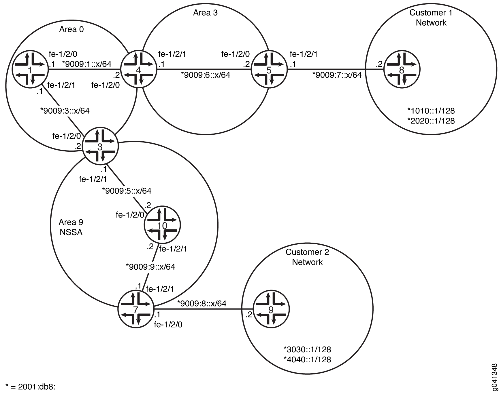
CLI Quick Configuration 显示了 图 11 中所有设备的配置。 #d26e123__d26e507 部分介绍了设备 3、设备 7 和设备 9 上的步骤。
配置
程序
CLI 快速配置
要快速配置此示例,请复制以下命令,将其粘贴到文本文件中,删除所有换行符,更改详细信息,以便与网络配置匹配,然后将命令复制并粘贴到层 [edit] 级的 CLI 中。
设备 1
set interfaces fe-1/2/0 unit 0 family inet6 address 2001:db8:9009:1::1/64
set interfaces fe-1/2/1 unit 0 family inet6 address 2001:db8:9009:3::1/64
set interfaces lo0 unit 0 family inet address 10.1.1.1/32
set protocols ospf3 area 0.0.0.0 interface fe-1/2/0.0
set protocols ospf3 area 0.0.0.0 interface fe-1/2/0.5
set protocols ospf3 area 0.0.0.0 interface fe-1/2/1.0
set protocols ospf3 area 0.0.0.0 interface lo0.0 passive
设备 3
set interfaces fe-1/2/0 unit 0 family inet6 address 2001:db8:9009:3::2/64
set interfaces fe-1/2/1 unit 0 family inet6 address 2001:db8:9009:5::1/64
set interfaces lo0 unit 0 family inet address 10.3.3.3/32
set protocols ospf3 area 0.0.0.0 interface fe-1/2/0.0
set protocols ospf3 area 0.0.0.0 interface lo0.0 passive
set protocols ospf3 area 0.0.0.9 nssa default-lsa default-metric 10
set protocols ospf3 area 0.0.0.9 nssa default-lsa metric-type 1
set protocols ospf3 area 0.0.0.9 nssa default-lsa type-7
set protocols ospf3 area 0.0.0.9 nssa no-summaries
set protocols ospf3 area 0.0.0.9 interface fe-1/2/1.0
设备 4
set interfaces fe-1/2/0 unit 0 family inet6 address 2001:db8:9009:1::2/64
set interfaces fe-1/2/1 unit 0 family inet6 address 2001:db8:9009:6::1/64
set interfaces lo0 unit 0 family inet address 10.4.4.4/32
set protocols ospf3 area 0.0.0.0 interface fe-1/2/0.0
set protocols ospf3 area 0.0.0.0 interface lo0.0 passive
set protocols ospf3 area 0.0.0.3 interface fe-1/2/1.0
设备 5
set interfaces fe-1/2/0 unit 0 family inet6 address 2001:db8:9009:6::2/64
set interfaces fe-1/2/1 unit 0 family inet6 address 2001:db8:9009:7::1/64
set interfaces lo0 unit 0 family inet address 10.5.5.5/32
set protocols ospf3 export static-to-ospf
set protocols ospf3 area 0.0.0.3 interface fe-1/2/0.0
set protocols ospf3 area 0.0.0.3 interface lo0.0 passive
set policy-options policy-statement static-to-ospf term 1 from protocol static
set policy-options policy-statement static-to-ospf term 1 then accept
set routing-options rib inet6.0 static route 2001:db8:1010::1/128 next-hop 2001:db8:9009:7::2
set routing-options rib inet6.0 static route 2001:db8:2020::1/128 next-hop 2001:db8:9009:7::2
设备 7
set interfaces fe-1/2/0 unit 0 family inet6 address 2001:db8:9009:8::1/64
set interfaces fe-1/2/1 unit 0 family inet6 address 2001:db8:9009:9::1/64
set interfaces lo0 unit 0 family inet address 10.7.7.7/32
set protocols ospf3 export static2-to-ospf
set protocols ospf3 area 0.0.0.9 nssa
set protocols ospf3 area 0.0.0.9 interface fe-1/2/1.0
set protocols ospf3 area 0.0.0.9 interface lo0.0 passive
set policy-options policy-statement static2-to-ospf term 1 from protocol static
set policy-options policy-statement static2-to-ospf term 1 then accept
set routing-options rib inet6.0 static route 2001:db8:3030::1/128 next-hop 2001:db8:9009:8::2
set routing-options rib inet6.0 static route 2001:db8:4040::1/128 next-hop 2001:db8:9009:8::2
设备 8
set interfaces fe-1/2/0 unit 0 family inet6 address 2001:db8:9009:7::2/64
set interfaces lo0 unit 0 family inet address 10.8.8.8/32
set interfaces lo0 unit 0 family inet6 address 2001:db8:1010::1/128
set interfaces lo0 unit 0 family inet6 address 2001:db8:2020::1/128
设备 9
set interfaces fe-1/2/0 unit 0 family inet6 address 2001:db8:9009:8::2/64
set interfaces lo0 unit 0 family inet address 10.9.9.9/32
set interfaces lo0 unit 0 family inet6 address 2001:db8:3030::1/128
set interfaces lo0 unit 0 family inet6 address 2001:db8:4040::1/128
设备 10
set interfaces fe-1/2/0 unit 0 family inet6 address 2001:db8:9009:5::2/64
set interfaces fe-1/2/1 unit 0 family inet6 address 2001:db8:9009:9::2/64
set interfaces lo0 unit 0 family inet address 10.10.10.10/32
set protocols ospf3 area 0.0.0.9 nssa
set protocols ospf3 area 0.0.0.9 interface fe-1/2/0.0
set protocols ospf3 area 0.0.0.9 interface fe-1/2/1.0
set protocols ospf3 area 0.0.0.9 interface lo0.0 passive
分步过程
下面的示例要求您在各个配置层级中进行导航。有关 CLI 导航的信息,请参阅 CLI 用户指南中的在配置模式下使用 CLI 编辑器。
要配置设备 3:
-
配置接口。
[edit interfaces]
user@3# set fe-1/2/0 unit 0 family inet6 address 2001:db8:9009:3::2/64
user@3# set fe-1/2/1 unit 0 family inet6 address 2001:db8:9009:5::1/64
user@3# set lo0 unit 0 family inet address 10.3.3.3/32
-
在区域 0 中的接口上启用 OSPFv3。
[edit protocols ospf3 area 0.0.0.0]
user@3# set interface fe-1/2/0.0
user@3# set interface lo0.0 passive
-
在区域 9 中的接口上启用 OSPFv3。
[edit protocols ospf3 area 0.0.0.9]
user@3# set interface fe-1/2/1.0
-
配置 OSPFv3 NSSA。
该区域中的所有路由设备都需要该
nssa语句。[edit protocols ospf3 area 0.0.0.9] user@3# set nssa
-
在 ABR 上,将默认路由注入到该区域。
[edit protocols ospf3 area 0.0.0.9] user@3# set default-lsa default-metric 10
-
(选答)在 ABR 上,指定默认路由的外部指标类型。
[edit protocols ospf3 area 0.0.0.9] user@3# set nssa default-lsa metric-type 1
-
(选答)在 ABR 上,指定 7 类 LSA 的泛洪。
[edit protocols ospf3 area 0.0.0.9]
user@3# set nssa default-lsa type-7
-
在 ABR 上,限制汇总 LSA 进入该区域。
[edit protocols ospf3 area 0.0.0.9]
user@3# set nssa no-summaries
分步过程
下面的示例要求您在各个配置层级中进行导航。有关 CLI 导航的信息,请参阅 CLI 用户指南中的在配置模式下使用 CLI 编辑器。
要配置设备 5:
-
配置接口。
[edit interfaces]
user@5# set fe-1/2/0 unit 0 family inet6 address 2001:db8:9009:6::2/64
user@5# set fe-1/2/1 unit 0 family inet6 address 2001:db8:9009:7::1/64
user@5# set lo0 unit 0 family inet address 10.5.5.5/32
-
在区域 3 中的接口上启用 OSPFv3。
[edit protocols ospf3 area 0.0.0.3]
user@5# set interface fe-1/2/0.0
user@5# set interface lo0.0 passive
-
配置静态路由,以便与客户路由建立连接。
[edit routing-options rib inet6.0 static]
user@5# set route 1010::1/128 next-hop 2001:db8:9009:7::2
user@5# set route 2020::1/128 next-hop 2001:db8:9009:7::2
-
配置路由策略以重新分配静态路由。
[edit policy-options policy-statement static-to-ospf term 1]
user@5# set from protocol static
user@5# set then accept
-
将路由策略应用于 OSPFv3 实例。
[edit protocols ospf3]
user@5# set export static-to-ospf
分步过程
下面的示例要求您在各个配置层级中进行导航。有关 CLI 导航的信息,请参阅 CLI 用户指南中的在配置模式下使用 CLI 编辑器。
要配置设备 7:
-
配置接口。
[edit interfaces]
user@7# set fe-1/2/0 unit 0 family inet6 address 2001:db8:9009:5::2/64
user@7# set fe-1/2/1 unit 0 family inet6 address 2001:db8:9009:7::1/64
user@7# set lo0 unit 0 family inet address 10.7.7.7/32
-
在区域 9 中的接口上启用 OSPFv3。
[edit protocols ospf3 area 0.0.0.9]
user@7# set interface fe-1/2/0.0
user@7# set interface lo0.0 passive
-
配置 OSPFv3 NSSA。
该区域中的所有路由设备都需要该
nssa语句。[edit protocols ospf3 area 0.0.0.9] user@7# set nssa
分步过程
下面的示例要求您在各个配置层级中进行导航。有关 CLI 导航的信息,请参阅 CLI 用户指南中的在配置模式下使用 CLI 编辑器。
要配置设备 8:
-
配置接口。
[edit interfaces]
user@8# set fe-1/2/0 unit 0 family inet6 address 2001:db8:9009:7::2/64
user@8# set lo0 unit 0 family inet address 10.8.8.8/32
-
配置两个环路接口地址以模拟客户路由。
[edit interfaces lo0 unit 0 family inet6]
user@8# set address 2001:db8:1010::1/128
user@8# set address 2001:db8:2020::1/128
结果
在配置模式下,输入show interfaces、show protocolsshow policy-options、和show routing-options命令,以确认您的配置。如果输出未显示预期的配置,请重复此示例中的说明以更正配置。
设备 3
user@3# show interfaces
fe-1/2/0 {
    unit 0 {
        family inet6 {
            address 2001:db8:9009:3::2/64;
        }
    }
}
fe-1/2/1 {
    unit 0 {
        family inet6 {
            address 2001:db8:9009:5::1/64;
        }
    }
}
lo0 {
    unit 0 {
        family inet {
            address 10.3.3.3/32;
        }
    }
}
}
user@3# show protocols
ospf3 {
    area 0.0.0.0 {
        interface fe-1/2/0.0;
        interface lo0.0 {
            passive;
        }
    }
    area 0.0.0.9 {
        nssa {
            default-lsa {
                default-metric 10;
                metric-type 1;
                type-7;
            }
            no-summaries;
        }
        interface fe-1/2/1.0;
    }
}
设备 5
user@5# show interfaces
fe-1/2/0 {
    unit 0 {
        family inet6 {
            address 2001:db8:9009:6::2/64;
        }
    }
}
fe-1/2/1 {
    unit 0 {
        family inet6 {
            address 2001:db8:9009:7::1/64;
        }
    }
}
lo0 {
    unit 0 {
        family inet {
            address 10.5.5.5/32;
        }
    }
}
user@5# show protocols
ospf3 {
    export static-to-ospf;
    area 0.0.0.3 {
        interface fe-1/2/0.0;
        interface lo0.0 {
            passive;
        }
    }
}
user@5# show policy-options
policy-statement static-to-ospf {
    term 1 {
        from protocol static;
        then accept;
    }
}
user@5# show routing-options
rib inet6.0 {
    static {
        route 2001:db8:1010::1/128 next-hop 2001:db8:9009:7::2;
        route 2001:db8:2020::1/128 next-hop 2001:db8:9009:7::2;
    }
}
设备 7
user@7# show interfaces
fe-1/2/0 {
    unit 0{
        family inet6 {
            address 2001:db8:9009:5::2/64;
        }
    }
}
lo0 {
    unit 0 {
        family inet {
            address 10.7.7.7/32;
        }
    }
}
user@7# show protocols
ospf3 {
    area 0.0.0.9 {
        nssa;
        interface fe-1/2/0.0;
        interface lo0.0 {
            passive;
        }
    }
}
设备 8
user@8# show interfaces
fe-1/2/0 {
    unit 0 {
        family inet6 {
            address 2001:db8:9009:7::2/64;
        }
    }
}
lo0 {
    unit 0 {
        family inet {
            address 10.8.8.8/32;
        }
        family inet6 {
            address 2001:db8:1010::1/128;
            address 2001:db8:2020::1/128;
        }
    }
}
如果完成设备配置,请从配置模式输入 commit 。
验证
确认配置工作正常。
验证 OSPFv3 区域的类型
目的
验证 OSPFv3 区域是否为 NSSA 区域。确认输出显示 Stub NSSA 为“存根类型”。
行动
在设备 3、设备 7 和设备 10 上的作模式下,输入 show ospf3 overview 命令。
user@3> show ospf3 overview
Instance: master
  Router ID: 10.3.3.3
  Route table index: 36
  Area border router, AS boundary router, NSSA router
  LSA refresh time: 50 minutes
  Area: 0.0.0.0
    Stub type: Not Stub
    Area border routers: 2, AS boundary routers: 0
    Neighbors
      Up (in full state): 1
  Area: 0.0.0.9
    Stub type: Stub NSSA, Stub cost: 10
    Area border routers: 0, AS boundary routers: 1
    Neighbors
      Up (in full state): 1
  Topology: default (ID 0)
    Prefix export count: 0
    Full SPF runs: 22
    SPF delay: 0.200000 sec, SPF holddown: 5 sec, SPF rapid runs: 3
    Backup SPF: Not Needed
user@7> show ospf3 overview
Instance: master
  Router ID: 10.7.7.7
  Route table index: 44
  AS boundary router, NSSA router
  LSA refresh time: 50 minutes
  Area: 0.0.0.9
    Stub type: Stub NSSA
    Area border routers: 1, AS boundary routers: 1
    Neighbors
      Up (in full state): 1
  Topology: default (ID 0)
    Prefix export count: 2
    Full SPF runs: 11
    SPF delay: 0.200000 sec, SPF holddown: 5 sec, SPF rapid runs: 3
    Backup SPF: Not Needed
user@10> show ospf3 overview
Instance: master
  Router ID: 10.10.10.10
  Route table index: 55
  NSSA router
  LSA refresh time: 50 minutes
  Area: 0.0.0.9
    Stub type: Stub NSSA
    Area border routers: 1, AS boundary routers: 2
    Neighbors
      Up (in full state): 2
  Topology: default (ID 0)
    Prefix export count: 0
    Full SPF runs: 6
    SPF delay: 0.200000 sec, SPF holddown: 5 sec, SPF rapid runs: 3
    Backup SPF: Not Needed
意义
在设备 3 上,区域 0 的存根类型为 Not Stub。区域 9 的存根类型为 Stub NSSA。存根默认指标为 10。
在设备 7 和设备 10 上,区域 9 的存根类型为 Stub NSSA。
验证 OSPFv3 剩余区域中的路由
目的
请确保路由表中存在预期的路由。
行动
在设备 7 和设备 3 的作模式下,输入 show route 命令。
user@7> show route
inet.0: 1 destinations, 1 routes (1 active, 0 holddown, 0 hidden)
+ = Active Route, - = Last Active, * = Both

10.7.7.7/32         *[Direct/0] 3d 03:00:23
                    > via lo0.0

inet6.0: 12 destinations, 14 routes (12 active, 0 holddown, 0 hidden)
+ = Active Route, - = Last Active, * = Both

::/0               *[OSPF3/150] 01:01:31, metric 12, tag 0
                    > via fe-1/2/1.0
2001:db8:3030::1/128        *[Static/5] 01:01:43
                    > to 9009:8::2 via fe-1/2/0.0
2001:db8:4040::1/128        *[Static/5] 01:01:43
                    > to 9009:8::2 via fe-1/2/0.0
2001:db8:9009:5::/64        *[OSPF3/10] 01:01:33, metric 2
                    > via fe-1/2/1.0
2001:db8:9009:8::/64        *[Direct/0] 01:01:43
                    > via fe-1/2/0.0
2001:db8:9009:8::1/128      *[Local/0] 01:02:01
                      Local via fe-1/2/0.0
2001:db8:9009:9::/64        *[Direct/0] 01:01:45
                    > via fe-1/2/1.0
                    [OSPF3/10] 01:01:44, metric 1
                    > via fe-1/2/1.0
2001:db8:9009:9::1/128      *[Local/0] 01:02:01
                      Local via fe-1/2/1.0
fe80::/64          *[Direct/0] 01:01:45
                    > via fe-1/2/1.0
                    [Direct/0] 01:01:43
                    > via fe-1/2/0.0
fe80::2a0:a514:0:f4c/128
                   *[Local/0] 01:02:01
                      Local via fe-1/2/0.0
fe80::2a0:a514:0:114c/128
                   *[Local/0] 01:02:01
                      Local via fe-1/2/1.0
ff02::5/128        *[OSPF3/10] 3d 03:01:25, metric 1
                      MultiRecv
user@10> show route
inet.0: 1 destinations, 1 routes (1 active, 0 holddown, 0 hidden)
+ = Active Route, - = Last Active, * = Both

10.10.10.10/32     *[Direct/0] 01:01:59
                    > via lo0.0

inet6.0: 11 destinations, 14 routes (11 active, 0 holddown, 0 hidden)
+ = Active Route, - = Last Active, * = Both

::/0               *[OSPF3/150] 01:01:35, metric 11, tag 0
                    > via fe-1/2/0.0
2001:db8:3030::1/128        *[OSPF3/150] 01:01:35, metric 0, tag 0
                    > via fe-1/2/1.0
2001:db8:4040::1/128        *[OSPF3/150] 01:01:35, metric 0, tag 0
                    > via fe-1/2/1.0
2001:db8:9009:5::/64        *[Direct/0] 01:01:50
                    > via fe-1/2/0.0
                    [OSPF3/10] 01:01:50, metric 1
                    > via fe-1/2/0.0
2001:db8:9009:5::2/128      *[Local/0] 01:01:50
                      Local via fe-1/2/0.0
2001:db8:9009:9::/64        *[Direct/0] 01:01:50
                    > via fe-1/2/1.0
                    [OSPF3/10] 01:01:40, metric 1
                    > via fe-1/2/1.0
2001:db8:9009:9::2/128      *[Local/0] 01:01:50
                      Local via fe-1/2/1.0
fe80::/64          *[Direct/0] 01:01:50
                    > via fe-1/2/0.0
                    [Direct/0] 01:01:50
                    > via fe-1/2/1.0
fe80::2a0:a514:0:c4c/128
                   *[Local/0] 01:01:50
                      Local via fe-1/2/0.0
fe80::2a0:a514:0:124c/128
                   *[Local/0] 01:01:50
                      Local via fe-1/2/1.0
ff02::5/128        *[OSPF3/10] 01:02:16, metric 1
                      MultiRecv
user@3> show route
inet.0: 1 destinations, 1 routes (1 active, 0 holddown, 0 hidden)
+ = Active Route, - = Last Active, * = Both

10.3.3.3/32         *[Direct/0] 3d 03:03:10
                    > via lo0.0

inet6.0: 15 destinations, 18 routes (15 active, 0 holddown, 0 hidden)
+ = Active Route, - = Last Active, * = Both

2001:db8:1010::1/128        *[OSPF3/150] 01:04:21, metric 0, tag 0
                    > via fe-1/2/0.0
2001:db8:2020::1/128        *[OSPF3/150] 01:04:21, metric 0, tag 0
                    > via fe-1/2/0.0
2001:db8:3030::1/128        *[OSPF3/150] 01:03:57, metric 0, tag 0
                    > via fe-1/2/1.0
2001:db8:4040::1/128        *[OSPF3/150] 01:03:57, metric 0, tag 0
                    > via fe-1/2/1.0
2001:db8:9009:1::/64        *[OSPF3/10] 3d 03:02:06, metric 2
                    > via fe-1/2/0.0
2001:db8:9009:3::/64        *[Direct/0] 3d 03:02:55
                    > via fe-1/2/0.0
                    [OSPF3/10] 3d 03:02:54, metric 1
                    > via fe-1/2/0.0
2001:db8:9009:3::2/128      *[Local/0] 3d 03:02:55
                      Local via fe-1/2/0.02001:db8:9009:5::/64        *[Direct/0] 01:04:09
                    > via fe-1/2/1.0
                    [OSPF3/10] 01:04:09, metric 1
                    > via fe-1/2/1.0
2001:db8:9009:5::1/128      *[Local/0] 3d 03:02:54
                      Local via fe-1/2/1.0
2001:db8:9009:6::/64        *[OSPF3/10] 3d 02:19:14, metric 3
                    > via fe-1/2/0.0
2001:db8:9009:9::/64        *[OSPF3/10] 01:04:02, metric 2
                    > via fe-1/2/1.0
fe80::/64          *[Direct/0] 3d 03:02:55
                    > via fe-1/2/0.0
                    [Direct/0] 01:04:09
                    > via fe-1/2/1.0
fe80::2a0:a514:0:84c/128
                   *[Local/0] 3d 03:02:55
                      Local via fe-1/2/0.0
fe80::2a0:a514:0:b4c/128
                   *[Local/0] 3d 03:02:54
                      Local via fe-1/2/1.0
ff02::5/128        *[OSPF3/10] 3d 03:03:50, metric 1
                      MultiRecv
意义
在设备 7 上,由于 default-metric ABR(设备 3)上的语句,已学习了默认路由。否则,设备 7 路由表中的唯一 OSPFv3 路由是区域 9 本地的路由,以及所有 SPF 链路状态路由器的 OSPFv3 组播地址 ff02::5/128,也称为 AllSPFRouters。
设备 10 具有设备 3 注入的默认路由以及设备 7 注入的 OSPF 外部路由。
设备 7 和设备 10 均不具有设备 5 注入到 OSPFv3 中的外部客户路由。
在设备 3 上,已学习所有 OSPFv3 路由,包括外部客户路由 2001:db8:1010::1/128 和 2001:db8:2020::1/128。
验证 LSA 的类型
目的
验证该区域中的 LSA 类型。
行动
在设备 7 的作模式下,输入 show ospf3 database nssa detail 命令。
user@7> show ospf3 database nssa detail
Area 0.0.0.9
 Type       ID               Adv Rtr           Seq         Age  Cksum  Len
NSSA        0.0.0.1          10.3.3.3          0x8000002a  1462  0xf406  28
  Prefix ::/0
  Prefix-options 0x0, Metric 10, Type 1,
NSSA       *0.0.0.1          10.7.7.7          0x80000003  1625  0x88df  60
  Prefix 2001:db8:3030::1/128
  Prefix-options 0x8, Metric 0, Type 2,
   Fwd addr 2001:db8:9009:9::1,
NSSA       *0.0.0.2          10.7.7.7          0x80000003  1025  0xef57  60
  Prefix 2001:db8:4040::1/128
  Prefix-options 0x8, Metric 0, Type 2,
   Fwd addr 2001:db8:9009:9::1,
意义
在设备 7 上,NSSA LSA 是从设备 3 获知的 1 类外部默认路由,以及通向客户 1 网络的 2 类外部静态路由。
了解不完全剩余区域过滤
您可能会遇到不需要将 7 类 LSA 导出到不那么剩余区域 (NSSA) 的情况。当自治系统边界路由器 (ASBR) 也是连接了 NSSA 的区域边界路由器 (ABR) 时,默认情况下,类型 7 LSA 将导出到 NSSA 中。
此外,当 ASBR(也是一个 ABR)连接到多个 NSSA 时,默认情况下会将单独的 7 类 LSA 导出到每个 NSSA 中。在路由重新分配期间,此路由设备会同时生成 5 类 LSA 和 7 类 LSA。因此,为避免同一路由被重新分发两次(从 5 类 LSA 和 7 类 LSA),您可以通过在路由设备上包含语 no-nssa-abr 句来禁用将 7 类 LSA 导出到 NSSA。
示例:使用过滤配置 OSPFv3 不完全剩余区域
此示例说明当不需要将外部路由作为 7 类链路状态通告 (LSA) 注入 NSSA 时,如何配置 OSPFv3 不完全剩余区域 (NSSA)。
要求
配置此示例之前,不需要除设备初始化之外的特殊配置。
概述
当自治系统边界路由器 (ASBR) 也是 NSSA 区域边界路由器 (ABR) 时,路由设备将生成 5 类和 7 类 LSA。您可以使用语 no-nssa-abr 句阻止路由器为 NSSA 创建类型 7 LSA。
在此示例中,设备 5 和设备 3 位于客户网络中。设备 4 和设备 2 都将客户路由注入到 OSPFv3 中。区域 1 是 NSSA。由于设备 4 既是 NSSA ABR 又是 ASBR,因此它会生成 7 类和 5 类 LSA,并将 7 类 LSA 注入区域 1,将 5 类 LSA 注入区域 0。要阻止将类型 7 LSA 注入区域 1, no-nssa-abr 请将语句包含在设备 4 配置中。
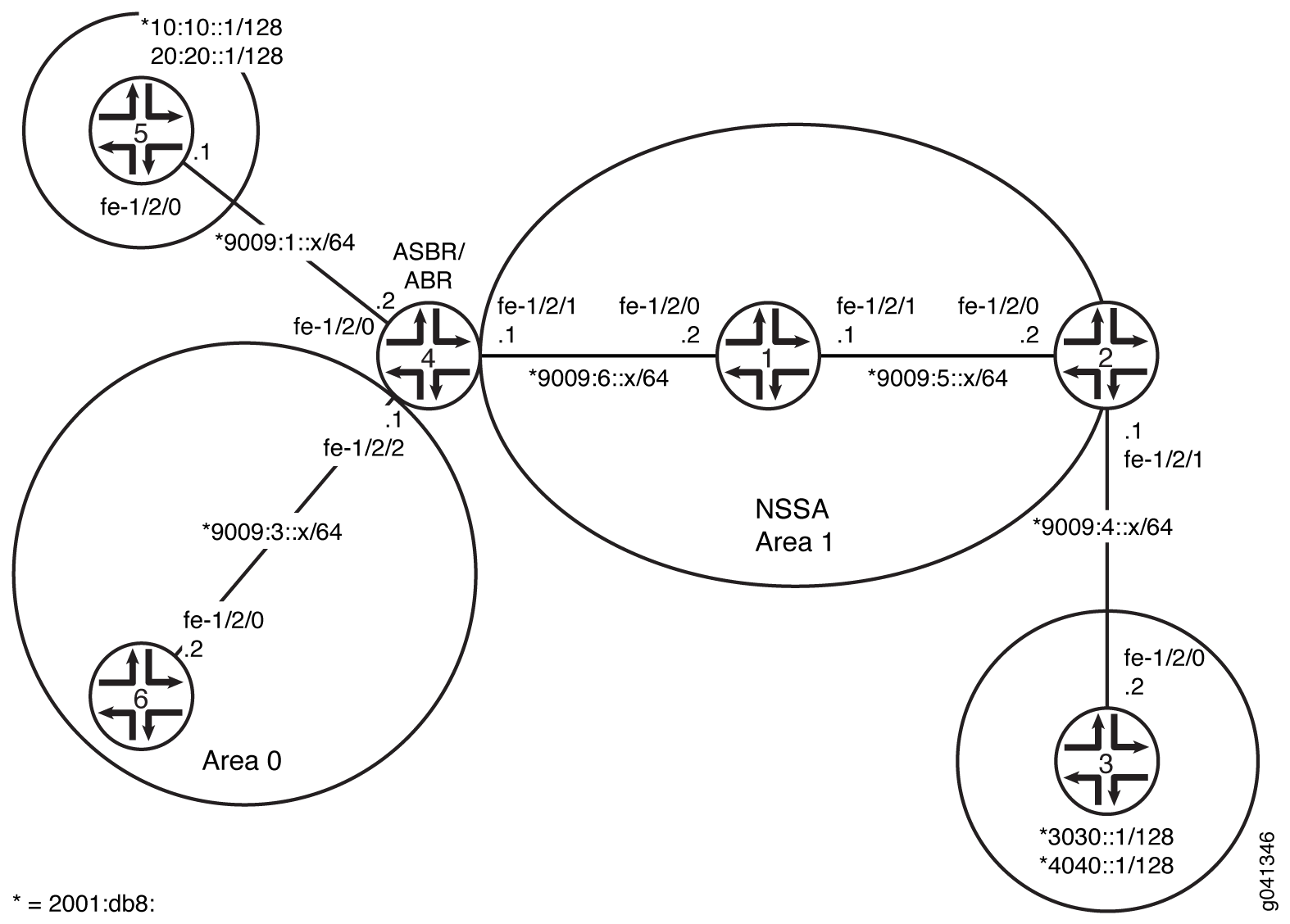
CLI Quick Configuration 显示了 图 12 中所有设备的配置。 #d28e64__d28e386 部分介绍了设备 4 上的步骤。
配置
程序
CLI 快速配置
要快速配置此示例,请复制以下命令,将其粘贴到文本文件中,删除所有换行符,更改详细信息,以便与网络配置匹配,然后将命令复制并粘贴到层 [edit] 级的 CLI 中。
设备 1
set interfaces fe-1/2/0 unit 0 family inet6 address 2001:db8:9009:6::2/64
set interfaces fe-1/2/1 unit 0 family inet6 address 2001:db8:9009:5::1/64
set interfaces lo0 unit 0 family inet address 0.1.1.1/32
set protocols ospf3 area 0.0.0.1 nssa
set protocols ospf3 area 0.0.0.1 interface fe-1/2/0.0
set protocols ospf3 area 0.0.0.1 interface fe-1/2/1.0
set protocols ospf3 area 0.0.0.1 interface lo0.0 passive
设备 2
set interfaces fe-1/2/0 unit 0 family inet6 address 2001:db8:9009:5::2/64
set interfaces fe-1/2/1 unit 0 family inet6 address 2001:db8:9009:4::1/64
set interfaces lo0 unit 0 family inet address 10.2.2.2/32
set protocols ospf3 export static2-to-ospf
set protocols ospf3 area 0.0.0.1 nssa
set protocols ospf3 area 0.0.0.1 interface fe-1/2/0.0
set protocols ospf3 area 0.0.0.1 interface lo0.0 passive
set policy-options policy-statement static2-to-ospf term 1 from protocol static
set policy-options policy-statement static2-to-ospf term 1 then accept
set routing-options rib inet6.0 static route 3030::1/128 next-hop 2001:db8:9009:4::2
set routing-options rib inet6.0 static route 4040::1/128 next-hop 2001:db8:9009:4::2
设备 3
set interfaces fe-1/2/0 unit 0 family inet6 address 2001:db8:9009:4::2/64
set interfaces lo0 unit 0 family inet address 10.3.3.3/32
set interfaces lo0 unit 0 family inet6 address 2001:db8:3030::1/128
set interfaces lo0 unit 0 family inet6 address 2001:db8:4040::1/128
set routing-options rib inet6.0 static route ::/0 next-hop 2001:db8:9009:4::1
设备 4
set interfaces fe-1/2/0 unit 0 family inet6 address 2001:db8:9009:1::2/64
set interfaces fe-1/2/1 unit 0 family inet6 address 2001:db8:9009:6::1/64
set interfaces fe-1/2/2 unit 0 family inet6 address 2001:db8:9009:3::1/64
set interfaces lo0 unit 0 family inet address 10.4.4.4/32
set protocols ospf3 export static-to-ospf
set protocols ospf3 no-nssa-abr
set protocols ospf3 area 0.0.0.0 interface fe-1/2/2.0
set protocols ospf3 area 0.0.0.0 interface lo0.0 passive
set protocols ospf3 area 0.0.0.1 nssa default-lsa default-metric 10
set protocols ospf3 area 0.0.0.1 nssa default-lsa metric-type 1
set protocols ospf3 area 0.0.0.1 nssa default-lsa type-7
set protocols ospf3 area 0.0.0.1 nssa no-summaries
set protocols ospf3 area 0.0.0.1 interface fe-1/2/1.0
set policy-options policy-statement static-to-ospf term 1 from protocol static
set policy-options policy-statement static-to-ospf term 1 then accept
set routing-options rib inet6.0 static route 2001:db8:1010::1/128 next-hop 2001:db8:9009:1::1
set routing-options rib inet6.0 static route 2001:db8:2020::1/128 next-hop 2001:db8:9009:1::1
设备 5
set interfaces fe-1/2/0 unit 0 family inet6 address 2001:db8:9009:1::1/64
set interfaces lo0 unit 0 family inet address 10.5.5.5/32
set interfaces lo0 unit 0 family inet6 address 2001:db8:1010::1/128
set interfaces lo0 unit 0 family inet6 address 2001:db8:2020::1/128
set routing-options rib inet6.0 static route ::/0 next-hop 2001:db8:9009:1::2
设备 6
set interfaces fe-1/2/0 unit 0 family inet6 address 2001:db8:9009:3::2/64
set interfaces lo0 unit 0 family inet address 10.6.6.6/32
set protocols ospf3 area 0.0.0.0 interface fe-1/2/0.0
set protocols ospf3 area 0.0.0.0 interface lo0.0 passive
分步过程
下面的示例要求您在各个配置层级中进行导航。有关 CLI 导航的信息,请参阅 CLI 用户指南中的“在配置模式下使用 CLI 编辑器”。
要配置设备 4:
-
配置接口。
[edit interfaces]
user@4# set fe-1/2/0 unit 0 family inet6 address 2001:db8:9009:1::2/64
user@4# set fe-1/2/1 unit 0 family inet6 address 2001:db8:9009:6::1/64
user@4# set fe-1/2/2 unit 0 family inet6 address 2001:db8:9009:3::1/64
user@4# set lo0 unit 0 family inet address 10.4.4.4/32
-
在区域 0 中的接口上启用 OSPFv3。
[edit protocols ospf3 area 0.0.0.0]
user@4# set interface fe-1/2/2.0
user@4# set interface lo0.0 passive
-
在区域 1 中的接口上启用 OSPFv3。
[edit protocols ospf3 area 0.0.0.1]
user@4# set interface fe-1/2/1.0
-
配置 OSPFv3 NSSA。
该区域中的所有路由设备都需要该
nssa语句。[edit protocols ospf3 area 0.0.0.1] user@4# set nssa
-
在 ABR 上,将默认路由注入到该区域。
[edit protocols ospf3 area 0.0.0.1] user@4# set nssa default-lsa default-metric 10
-
(选答)在 ABR 上,指定默认路由的外部指标类型。
[edit protocols ospf3 area 0.0.0.1]
user@4# set nssa default-lsa metric-type 1
-
(选答)在 ABR 上,指定 7 类 LSA 的泛洪。
[edit protocols ospf3 area 0.0.0.1]
user@4# set nssa default-lsa type-7
-
在 ABR 上,限制汇总 LSA 进入该区域。
[edit protocols ospf3 area 0.0.0.1]
user@4# set nssa no-summaries
-
禁止将 7 类 LSA 导出到 NSSA。
如果您的 AS 边界路由器也是连接了 NSSA 区域的 ABR,则此设置很有用。
[edit protocols ospf3]
user@4# set no-nssa-abr
-
配置到客户网络的静态路由。
[edit routing-options rib inet6.0 static]
user@4# set route 2001:db8:1010::1/128 next-hop 2001:db8:9009:1::1
user@4# set route 2001:db8:2020::1/128 next-hop 2001:db8:9009:1::1
-
配置策略以将静态路由注入到 OSPFv3 中。
[edit policy-options policy-statement static-to-ospf term 1]
user@4# set from protocol static
user@4# set then accept
-
将策略应用于 OSPFv3。
[edit protocols ospf3]
user@4# set export static-to-ospf
结果
在配置模式下,输入show interfaces、show protocolsshow policy-options、和show routing-options命令,以确认您的配置。如果输出未显示预期的配置,请重复此示例中的说明以更正配置。
设备 4
user@4# show interfaces
fe-1/2/0 {
    unit 0 {
        family inet6 {
            address 2001:db8:9009:1::2/64;
        }
    }
    unit 0 {
        family inet6 {
            address 2001:db8:9009:6::1/64;
        }
    }
    unit 0 {
        family inet6 {
            address 2001:db8:9009:3::1/64;
        }
    }
}
lo0 {
    unit 0 {
        family inet {
            address 10.4.4.4/32;
        }
    }
}
user@4# show protocols
ospf3 {
    export static-to-ospf;
    no-nssa-abr;
    area 0.0.0.0 {
        interface fe-1/2/2.0;
        interface lo0.0 {
            passive;
        }
    }
    area 0.0.0.1 {
        nssa {
            default-lsa {
                default-metric 10;
                metric-type 1;
                type-7;
            }
            no-summaries;
        }
        interface fe-1/2/1.0;
    }
}
user@4# show policy-options
policy-statement static-to-ospf {
    term 1 {
        from protocol static;
        then accept;
    }
}
user@4# show routing-options
rib inet6.0 {
    static {
        route 2001:db8:1010::1/128 next-hop 2001:db8:9009:1::1;
        route 2001:db8:2020::1/128 next-hop 2001:db8:9009:1::1;
    }
}
如果完成设备配置,请从配置模式输入 commit 。
验证
确认配置工作正常。
验证 OSPFv3 剩余区域中的路由
目的
请确保路由表中存在预期的路由。
行动
在设备 1 和设备 6 上的作模式下,输入 show route 命令。
user@1> show route
inet.0: 1 destinations, 1 routes (1 active, 0 holddown, 0 hidden)
+ = Active Route, - = Last Active, * = Both

0.1.1.1/32         *[Direct/0] 03:25:44
                    > via lo0.0

inet6.0: 11 destinations, 14 routes (11 active, 0 holddown, 0 hidden)
+ = Active Route, - = Last Active, * = Both

::/0               *[OSPF3/150] 01:52:58, metric 11, tag 0
                    > via fe-1/2/0.0
2001:db8:3030::1/128        *[OSPF3/150] 02:44:02, metric 0, tag 0
                    > via fe-1/2/1.0
2001:db8:4040::1/128        *[OSPF3/150] 02:44:02, metric 0, tag 0
                    > via fe-1/2/1.0
2001:db8:9009:5::/64        *[Direct/0] 03:25:34
                    > via fe-1/2/1.0
                    [OSPF3/10] 03:25:24, metric 1
                    > via fe-1/2/1.0
2001:db8:9009:5::1/128      *[Local/0] 03:25:34
                      Local via fe-1/2/1.0
2001:db8:9009:6::/64        *[Direct/0] 03:25:34
                    > via fe-1/2/0.0
                    [OSPF3/10] 03:25:34, metric 1
                    > via fe-1/2/0.0
2001:db8:9009:6::2/128      *[Local/0] 03:25:34
                      Local via fe-1/2/0.0
fe80::/64          *[Direct/0] 03:25:34
                    > via fe-1/2/0.0
                    [Direct/0] 03:25:34
                    > via fe-1/2/1.0
fe80::2a0:a514:0:44c/128
                   *[Local/0] 03:25:34
                      Local via fe-1/2/0.0
fe80::2a0:a514:0:74c/128
                   *[Local/0] 03:25:34
                      Local via fe-1/2/1.0
ff02::5/128        *[OSPF3/10] 03:27:00, metric 1
                      MultiRecv
user@6> show route
inet.0: 1 destinations, 1 routes (1 active, 0 holddown, 0 hidden)
+ = Active Route, - = Last Active, * = Both

10.6.6.6/32         *[Direct/0] 03:26:57
                    > via lo0.0

inet6.0: 11 destinations, 12 routes (11 active, 0 holddown, 0 hidden)
+ = Active Route, - = Last Active, * = Both

2001:db8:1010::1/128        *[OSPF3/150] 03:16:59, metric 0, tag 0
                    > via fe-1/2/0.0
2001:db8:2020::1/128        *[OSPF3/150] 03:16:59, metric 0, tag 0
                    > via fe-1/2/0.0
2001:db8:3030::1/128        *[OSPF3/150] 02:44:34, metric 0, tag 0
                    > via fe-1/2/0.0
2001:db8:4040::1/128        *[OSPF3/150] 02:44:34, metric 0, tag 0
                    > via fe-1/2/0.0
2001:db8:9009:3::/64        *[Direct/0] 03:26:29
                    > via fe-1/2/0.0
                    [OSPF3/10] 03:26:29, metric 1
                    > via fe-1/2/0.0
2001:db8:9009:3::2/128      *[Local/0] 03:26:29
                      Local via fe-1/2/0.0
2001:db8:9009:5::/64        *[OSPF3/10] 02:44:34, metric 3
                    > via fe-1/2/0.0
2001:db8:9009:6::/64        *[OSPF3/10] 03:16:59, metric 2
                    > via fe-1/2/0.0
fe80::/64          *[Direct/0] 03:26:29
                    > via fe-1/2/0.0
fe80::2a0:a514:0:64c/128
                   *[Local/0] 03:26:29
                      Local via fe-1/2/0.0
ff02::5/128        *[OSPF3/10] 03:27:37, metric 1
                      MultiRecv
意义
在设备 1 上,由于 default-metric ABR、设备 4 上的语句,已学习默认路由 (::/0)。客户路由 2001:db8:3030::1 和 2001:db8:4040::1 已从设备 2 获知。2001:db8:1010::1 和 2001:db8:2020::1 路由已隐含。不需要它们,因为可以改用默认路由。
在区域 0 中的设备 6 上,已学习所有客户路由。
验证 LSA 的类型
目的
验证该区域中的 LSA 类型。
行动
在设备 1 的作模式下,输入 show ospf3 database nssa detail 命令。
user@4> show ospf3 database nssa detail
Area 0.0.0.1
 Type       ID               Adv Rtr           Seq         Age  Cksum  Len
NSSA        0.0.0.1          10.2.2.2          0x80000004  2063  0xceaf  60
  Prefix 3030::1/128
  Prefix-options 0x8, Metric 0, Type 2,
   Fwd addr 2001:db8:9009:5::2,
NSSA        0.0.0.2          10.2.2.2          0x80000004  1463  0x3627  60
  Prefix 4040::1/128
  Prefix-options 0x8, Metric 0, Type 2,
   Fwd addr 2001:db8:9009:5::2,
NSSA       *0.0.0.1          10.4.4.4          0x80000003    35  0x25f8  28
  Prefix ::/0
  Prefix-options 0x0, Metric 10, Type 1,
意义
设备 4 未为客户路由 2001:db8:1010::1/128 和 2001:db8:2020::1/128 发送类型 7 (NSSA) LSA。如果要删除或停用该 no-nssa-abr 语句,然后重新运行 show ospf3 database nssa detail 命令,您将看到设备 4 正在为 2001:db8:1010::1/128 和 2001:db8:2020::1/128 发送类型 7 LSA。
了解非连续区域的 OSPF 虚拟链路
OSPF 要求自治系统 (AS) 中的所有区域都必须物理连接到主干区域(区域 0)。在具有许多区域的大型网络中,所有区域与主干区域之间的直接连接在物理上是困难的或是不可能的,您可以配置虚拟链路来连接不连续区域。虚拟链路使用包含两个或两个以上区域边界路由器 (ABR) 的中转区域将网络流量从一个相邻区域传递到另一个相邻区域。中转区域必须具有完整的路由信息,并且不能是剩余区域。例如, 图 13 显示了非连续区域和主干区域之间的虚拟链接,该链接通过与两者相连的区域进行。
路的 OSPF 拓扑
在 图 13 所示的拓扑中,区域 0.0.0.3 和通过区域 0.0.0.2 的骨干区域之间建立了虚拟链路。虚拟链路通过区域 0.0.0.2。发往其他区域的所有出站流量都通过区域 0.0.0.2 路由到主干区域,然后再路由到相应的 ABR。所有发往区域 0.0.0.3 的入站流量都将路由到骨干区域,然后通过区域 0.0.0.2。
示例:配置 OSPF 虚拟链路以连接不连续区域
此示例说明如何配置 OSPF 虚拟链路以连接不连续区域。
要求
开始之前:
配置设备接口。请参阅 路由设备 Junos OS 网络接口库。
配置单区域 OSPF 网络。请参阅 示例:配置单区域 OSPF 网络。
配置多区域 OSPF 网络。请参阅 示例:配置多区域 OSPF 网络。
概述
如果主干网上的任何路由设备未与主干网物理连接,则必须在该路由设备与主干网之间建立虚拟连接,以连接不连续区域。
要配置通过某个区域的 OSPF 虚拟链路,请指定虚拟链路两端路由设备的路由器 ID(IP 地址)。这些路由设备必须是区域边界路由器 (ABR),其中一个物理连接到主干网。您无法通过剩余区域配置虚拟链路。您还必须指定虚拟链路通过的区域(也称为中转区域)的数量。您可以将这些设置应用到作为虚拟链路一部分的 ABR 上的骨干区域(由区域 0.0.0.0 定义)配置。
在此示例中,设备 R1 和设备 R2 是虚拟链路两端的路由设备,设备 R1 物理连接到主干网,如 图 14 所示。您可以配置以下虚拟链路设置:
neighbor-id — 指定虚拟链路另一端路由设备的 IP 地址。在此示例中,设备 R1 的路由器 ID 为 192.0.2.5,设备 R2 的路由器 ID 为 192.0.2.3。
transit-area — 指定虚拟链路通过的区域标识符。在此示例中,区域 0.0.0.3 未连接到主干网,因此您可以在区域 0.0.0.3 和主干区域之间通过区域 0.0.0.2 配置虚拟链路会话。区域 0.0.0.2 是中转区域。
 路
路
拓扑学
配置
CLI 快速配置
要在本地路由设备(设备 R1)上快速配置 OSPF 虚拟链路,请将以下命令复制粘贴到 CLI 中。
注意:您必须配置属于虚拟链路的两台路由设备,并在每个路由设备上指定适用的邻接方 ID。
[edit]
set routing-options router-id 192.0.2.5
set protocols ospf area 0.0.0.0 virtual-link neighbor-id 192.0.2.3 transit-area 0.0.0.2
要在远程路由设备(设备 R2)上快速配置 OSPF 虚拟链路,请将以下命令复制粘贴到 CLI 中。
[edit]
set routing-options router-id 192.0.2.3
set protocols ospf area 0.0.0.0 virtual-link neighbor-id 192.0.2.5 transit-area 0.0.0.2
程序
分步过程
要在本地路由设备(设备 R1)上配置 OSPF 虚拟链路,请执行以下作:
配置路由器 ID。
[edit]
user@R1# set routing-options router-id 192.0.2.5
进入OSPF配置模式,指定OSPF区域0.0.0.0。
注意:对于 OSPFv3 虚拟链路,请在
[edit protocols]层次结构级别包含ospf3语句。[edit] user@R1# edit protocols ospf area 0.0.0.0
配置 OSPF 虚拟链路并指定中转区域 0.0.0.2。 此路由设备必须是物理连接到主干网的 ABR。
[edit protocols ospf area 0.0.0.0]
user@R1# set virtual-link neighbor-id 192.0.2.3 transit-area 0.0.0.2
如果完成设备配置,请提交配置。
[edit protocols ospf area 0.0.0.0]
user@R1# commit
分步过程
要在远程 ABR(设备 R2,链路另一端的路由设备)上配置 OSPF 虚拟链路,请执行以下作:
配置路由器 ID。
[edit] user@R2# set routing-options router-id 192.0.2.3
进入OSPF配置模式,指定OSPF区域0.0.0.0。
注意:对于 OSPFv3 虚拟链路,请在
[edit protocols]层次结构级别包含ospf3语句。[edit] user@R2# edit protocols ospf area 0.0.0.0
在远程 ABR 上配置 OSPF 虚拟链路并指定中转区域 0.0.0.2。 此路由设备未与主干网进行物理连接。
[edit protocols ospf area 0.0.0.0] user@R2# set virtual-link neighbor-id 192.0.2.5 transit-area 0.0.0.2
如果完成设备配置,请提交配置。
[edit protocols ospf area 0.0.0.0] user@R2# commit
结果
输入 show routing-options 和命令, show protocols ospf 以确认您的配置。如果输出未显示预期的配置,请重复此示例中的说明以更正配置。
本地路由设备(设备 R1)上的配置:
user@R1#: show routing-options
router-id 192.0.2.5;
user@R1# show protocols ospf
area 0.0.0.0 {
virtual-link neighbor-id 192.0.2.3 transit-area 0.0.0.2;
}
远程 ABR(设备 R2)上的配置:
user@R2#: show routing-options
router-id 192.0.2.3;
user@R2# show protocols ospf
area 0.0.0.0 {
virtual-link neighbor-id 192.0.2.5 transit-area 0.0.0.2;
}
要确认您的 OSPFv3 配置,请输入 show protocols ospf3 命令。
验证
确认配置工作正常。
验证链路状态数据库中的条目
目的
验证是否显示 OSPFv2 或 OSPFv3 链路状态数据库中的条目。OSPFv2 输出中的路由器字段显示 LSA 信息,包括链路类型。如果配置为虚拟链路,则“类型”为“虚拟”。对于每个路由器链路,OSPFv3 输出中的“类型”字段会显示接口类型。如果配置为虚拟链路,则“类型”为“虚拟”。
行动
在作模式下, show ospf database detail 输入适用于 OSPFv2 的命令,然后 show ospf3 database detail 输入适用于 OSPFv3 的命令。
示例:配置 OSPFv3 虚拟链路
此示例说明如何使用某些与主干区域(区域 0)没有直接邻接关系的区域配置 OSPF 版本 3 (OSPFv3)。当区域与区域 0 缺乏邻接时,需要虚拟链路才能通过非主干区域连接到主干网。配置虚拟链路所需的区域(称为中转区域)必须具有完整的路由信息。过境区域不能是剩余区域。
要求
配置此示例之前,不需要除设备初始化之外的特殊配置。
概述
图 15 显示了此示例中使用的拓扑。
 路的 OSPFv3
设备 0、设备 1、设备 2 和设备 3 连接到 OSPFv3 骨干区域 0。设备 2、设备 3 和设备 4 跨区域 1 相互连接。区域 2 位于设备 4 和设备 5 之间。由于设备 5 与区域 0 没有直接邻接关系,因此设备 3 和设备 4 之间需要跨区域 1 的虚拟链路。同样,由于设备 0 和设备 1 有两个独立的区域 0 骨干网段,因此您需要在设备 2 和设备 3 之间跨区域 1 配置第二个虚拟链路。
配置
程序
CLI 快速配置
要快速配置此示例,请复制以下命令,将其粘贴到文本文件中,删除所有换行符,更改详细信息,以便与网络配置匹配,然后将命令复制并粘贴到层 [edit] 级的 CLI 中。
设备 0
set logical-systems 0 interfaces so-0/3/2 unit 0 family inet6 address 9009:1::1/64 set logical-systems 0 interfaces lo0 unit 0 family inet address 192.168.0.1/32 set logical-systems 0 interfaces lo0 unit 0 family inet6 address feee::10:255:71:4/128 set logical-systems 0 protocols ospf3 area 0.0.0.0 interface so-0/3/2.0 set logical-systems 0 protocols ospf3 area 0.0.0.0 interface lo0.0 passive set logical-systems 0 routing-options router-id 192.168.0.1
设备 1
set logical-systems 1 interfaces at-2/0/0 atm-options vpi 0 set logical-systems 1 interfaces at-2/0/0 unit 0 family inet6 address 9009:2::1/64 set logical-systems 1 interfaces at-2/0/0 unit 0 vci 0.77 set logical-systems 1 interfaces lo0 unit 0 family inet address 192.168.1.1/32 set logical-systems 1 interfaces lo0 unit 0 family inet6 address feee::10:255:71:1/128 set logical-systems 1 protocols ospf3 area 0.0.0.0 interface at-2/0/0.0 set logical-systems 1 protocols ospf3 area 0.0.0.0 interface lo0.0 passive set logical-systems 1 routing-options router-id 192.168.1.1
设备 2
set logical-systems 2 interfaces so-0/2/0 unit 0 family inet6 address 9009:3::1/64 set logical-systems 2 interfaces fe-1/1/0 unit 0 family inet6 address 9009:4::1/64 set logical-systems 2 interfaces at-0/3/1 atm-options vpi 0 maximum-vcs 1200 set logical-systems 2 interfaces at-0/3/1 unit 0 family inet6 address 9009:2::2/64 set logical-systems 2 interfaces at-0/3/1 unit 0 vci 0.77 set logical-systems 2 interfaces lo0 unit 0 family inet address 192.168.2.1/32 set logical-systems 2 interfaces lo0 unit 0 family inet6 address feee::10:255:71:11/128 set logical-systems 2 protocols ospf3 area 0.0.0.0 virtual-link neighbor-id 192.168.3.1 transit-area 0.0.0.1 set logical-systems 2 protocols ospf3 area 0.0.0.0 interface at-0/3/1.0 set logical-systems 2 protocols ospf3 area 0.0.0.1 interface fe-1/1/0.0 set logical-systems 2 protocols ospf3 area 0.0.0.1 interface so-0/2/0.0 set logical-systems 2 protocols ospf3 area 0.0.0.1 interface lo0.0 passive set logical-systems 2 routing-options router-id 192.168.2.1
设备 3
set logical-systems 3 interfaces so-0/3/2 unit 0 family inet6 address 9009:1::2/64 set logical-systems 3 interfaces t1-0/2/1 unit 0 family inet6 address 9009:5::1/64 set logical-systems 3 interfaces so-0/3/0 unit 0 family inet6 address 9009:3::2/64 set logical-systems 3 interfaces lo0 unit 0 family inet address 192.168.3.1/32 set logical-systems 3 interfaces lo0 unit 0 family inet6 address feee::10:255:71:3/128 set logical-systems 3 protocols ospf3 area 0.0.0.1 interface so-0/3/0.0 set logical-systems 3 protocols ospf3 area 0.0.0.1 interface t1-0/2/1.0 set logical-systems 3 protocols ospf3 area 0.0.0.1 interface lo0.0 passive set logical-systems 3 protocols ospf3 area 0.0.0.0 virtual-link neighbor-id 192.168.2.1 transit-area 0.0.0.1 set logical-systems 3 protocols ospf3 area 0.0.0.0 virtual-link neighbor-id 192.168.4.1 transit-area 0.0.0.1 set logical-systems 3 protocols ospf3 area 0.0.0.0 interface so-0/3/2.0 set logical-systems 3 routing-options router-id 192.168.3.1
设备 4
set logical-systems 4 interfaces t1-0/2/1 unit 0 family inet6 address 9009:5::2/64 set logical-systems 4 interfaces fe-0/0/0 unit 0 family inet6 address 9009:6::1/64 set logical-systems 4 interfaces fe-1/1/0 unit 0 family inet6 address 9009:4::2/64 set logical-systems 4 interfaces lo0 unit 0 family inet address 192.168.4.1/32 set logical-systems 4 interfaces lo0 unit 0 family inet6 address feee::10:255:71:5/128 set logical-systems 4 protocols ospf3 area 0.0.0.1 interface fe-1/1/0.0 set logical-systems 4 protocols ospf3 area 0.0.0.1 interface t1-0/2/1.0 set logical-systems 4 protocols ospf3 area 0.0.0.1 interface lo0.0 passive set logical-systems 4 protocols ospf3 area 0.0.0.2 interface fe-0/0/0.0 set logical-systems 4 protocols ospf3 area 0.0.0.0 virtual-link neighbor-id 192.168.3.1 transit-area 0.0.0.1 set logical-systems 4 routing-options router-id 192.168.4.1
设备 5
set logical-systems 5 interfaces fe-0/0/0 unit 0 family inet6 address 9009:6::2/64 set logical-systems 5 interfaces lo0 unit 0 family inet address 192.168.5.1/32 set logical-systems 5 interfaces lo0 unit 0 family inet6 address feee::10:255:71:6/128 set logical-systems 5 protocols ospf3 area 0.0.0.2 interface fe-0/0/0.0 set logical-systems 5 protocols ospf3 area 0.0.0.2 interface lo0.0 passive set logical-systems 5 routing-options router-id 192.168.5.1
分步过程
下面的示例要求您在各个配置层级中进行导航。有关 CLI 导航的信息,请参阅 CLI 用户指南中的在配置模式下使用 CLI 编辑器。
要配置设备 0:
配置接口。
[edit interfaces] user@0# set so-0/3/2 unit 0 family inet6 address 9009:1::1/64 user@0# set lo0 unit 0 family inet address 192.168.0.1/32 user@0# set lo0 unit 0 family inet6 address feee::10:255:71:4/128
将接口添加到 OSPFv3 进程的区域 0 中。
[edit protocols ospf3 area 0.0.0.0] user@0# set interface so-0/3/2.0 user@0# set interface lo0.0 passive
配置路由器 ID。
[edit routing-options] user@0# set router-id 192.168.0.1
分步过程
下面的示例要求您在各个配置层级中进行导航。有关 CLI 导航的信息,请参阅 CLI 用户指南中的在配置模式下使用 CLI 编辑器。
要配置设备 1:
配置接口。
[edit interfaces] user@1# set at-2/0/0 atm-options vpi 0 user@1# set at-2/0/0 unit 0 family inet6 address 9009:2::1/64 user@1# set at-2/0/0 unit 0 vci 0.77 user@1# set lo0 unit 0 family inet address 192.168.1.1/32 user@1# set lo0 unit 0 family inet6 address feee::10:255:71:1/128
将接口添加到 OSPFv3 进程的区域 0 中。
[edit protocols ospf3 area 0.0.0.0] user@1# set interface at-2/0/0.0 user@1# set interface lo0.0 passive
配置路由器 ID。
[edit routing-options] user@1# set router-id 192.168.1.1
分步过程
下面的示例要求您在各个配置层级中进行导航。有关 CLI 导航的信息,请参阅 CLI 用户指南中的在配置模式下使用 CLI 编辑器。
要配置设备 2:
配置接口。
[edit interfaces] user@2# set so-0/2/0 unit 0 family inet6 address 9009:3::1/64 user@2# set fe-1/1/0 unit 0 family inet6 address 9009:4::1/64 user@2# set at-0/3/1 atm-options vpi 0 maximum-vcs 1200 user@2# set at-0/3/1 unit 0 family inet6 address 9009:2::2/64 user@2# set at-0/3/1 unit 0 vci 0.77 user@2# set lo0 unit 0 family inet address 192.168.2.1/32 user@2# set lo0 unit 0 family inet6 address feee::10:255:71:11/128
将连接到设备 1、设备 3 和设备 4 的接口添加到 OSPFv3 进程中。
[edit protocols ospf3 area 0.0.0.0] user@2# set interface at-0/3/1.0 [edit protocols ospf3 area 0.0.0.1] user@2# set interface fe-1/1/0.0 user@2# set interface so-0/2/0.0 user@2# set interface lo0.0 passive
配置通过区域 1 到设备 3 的虚拟链路,以便设备 1 可以访问设备 0 上找到的 OSPF 主干的不连续部分。
[edit protocols ospf3 area 0.0.0.0] user@2# set virtual-link neighbor-id 192.168.3.1 transit-area 0.0.0.1
配置路由器 ID。
[edit routing-options] user@2# set router-id 192.168.2.1
分步过程
下面的示例要求您在各个配置层级中进行导航。有关 CLI 导航的信息,请参阅 CLI 用户指南中的在配置模式下使用 CLI 编辑器。
要配置设备 3:
配置接口。
[edit interfaces] user@3# set so-0/3/2 unit 0 family inet6 address 9009:1::2/64 user@3# set t1-0/2/1 unit 0 family inet6 address 9009:5::1/64 user@3# set so-0/3/0 unit 0 family inet6 address 9009:3::2/64 user@3# set lo0 unit 0 family inet address 192.168.3.1/32 user@3# set lo0 unit 0 family inet6 address feee::10:255:71:3/128
对于设备 3 上的 OSPFv3 进程,将连接到设备 2 和设备 4 的接口配置到区域 1 中,将连接到设备 0 的接口配置到区域 0 中。
[edit protocols ospf3 area 0.0.0.1] user@3# set interface so-0/3/0.0 user@3# set interface t1-0/2/1.0 user@3# set interface lo0.0 passive [edit protocols ospf3 area 0.0.0.0] user@3# set interface so-0/3/2.0
通过区域 1 配置两个虚拟链路 - 一个连接到设备 2,另一个连接到设备 4。
虚拟链路允许设备 5 访问 OSPF 主干网,并连接位于设备 0 和设备 1 的区域 0 的不连续部分。
[edit protocols ospf3 area 0.0.0.0] user@3# set virtual-link neighbor-id 192.168.2.1 transit-area 0.0.0.1 user@3# set virtual-link neighbor-id 192.168.4.1 transit-area 0.0.0.1
配置路由器 ID。
[edit routing-options] user@3# set router-id 192.168.3.1
分步过程
下面的示例要求您在各个配置层级中进行导航。有关 CLI 导航的信息,请参阅 CLI 用户指南中的在配置模式下使用 CLI 编辑器。
要配置设备 4:
配置接口。
[edit interfaces] user@4# set t1-0/2/1 unit 0 family inet6 address 9009:5::2/64 user@4# set fe-0/0/0 unit 0 family inet6 address 9009:6::1/64 user@4# set fe-1/1/0 unit 0 family inet6 address 9009:4::2/64 user@4# set lo0 unit 0 family inet address 192.168.4.1/32 user@4# set lo0 unit 0 family inet6 address feee::10:255:71:5/128
在设备 4 上,将连接的接口添加到 OSPFv3 进程中。
[edit protocols ospf3 area 0.0.0.1] user@4# set interface fe-1/1/0.0 user@4# set interface t1-0/2/1.0 user@4# set interface lo0.0 passive [edit protocols ospf3 area 0.0.0.2] user@4# set interface fe-0/0/0.0
通过区域 1 配置到设备 3 的虚拟链路,以便设备 5 可以访问 OSPF 骨干网。
[edit protocols ospf3 area 0.0.0.0] user@4# set virtual-link neighbor-id 192.168.3.1 transit-area 0.0.0.1
配置路由器 ID。
[edit routing-options] user@4# set router-id 192.168.4.1
分步过程
下面的示例要求您在各个配置层级中进行导航。有关 CLI 导航的信息,请参阅 CLI 用户指南中的在配置模式下使用 CLI 编辑器。
要配置设备 5:
配置接口。
[edit interfaces] user@5# set fe-0/0/0 unit 0 family inet6 address 9009:6::2/64 user@5# set lo0 unit 0 family inet address 192.168.5.1/32 user@5# set lo0 unit 0 family inet6 address feee::10:255:71:6/128
将接口添加到 OSPFv3 进程中。
[edit protocols ospf3 area 0.0.0.2] user@5# set interface fe-0/0/0.0 user@5# set interface lo0.0 passive
配置路由器 ID。
[edit routing-options] user@5# set router-id 192.168.5.1
结果
在配置模式下,输入show interfacesshow protocols、和show routing-options命令,以确认您的配置。如果输出未显示预期的配置,请重复此示例中的说明以更正配置。
设备 0
user@0#show interfacesso-0/3/2 { unit 0 { family inet6 { address 9009:1::1/64; } } } lo0 { unit 0 { family inet { address 192.168.0.1/32; } family inet6 { address feee::10:255:71:4/128; } } } user@0#show protocolsospf3 { area 0.0.0.0 { interface so-0/3/2.0; interface lo0.0 { passive; } } } user@0#show routing-optionsrouter-id 192.168.0.1;
设备 1
user@1#show interfacesat-2/0/0 { atm-options { vpi 0; } unit 0 { family inet6 { address 9009:2::1/64; } } } lo0 { unit 0 { family inet { address 192.168.1.1/32; } family inet6 { address feee::10:255:71:1/128; } } } user@1#show protocolsospf3 { area 0.0.0.0 { interface at-2/0/0.0; interface lo0.0 { passive; } } } user@1#show routing-optionsrouter-id 192.168.1.1;
设备 2
user@2#show interfacesso-0/2/0 { unit 0 { family inet6 { address 9009:3::1/64; } } } fe-1/1/0 { unit 0 { family inet6 { address 9009:4::1/64; } } } at-0/3/1 { atm-options { vpi 0 { maximum-vcs 1200; } } unit 0 { vci 0.77; family inet6 { address 9009:2::2/64; } } } lo0 { unit 0 { family inet { address 192.168.2.1/32; } family inet6 { address feee::10:255:71:11/128; } } } user@2#show protocolsospf3 { area 0.0.0.0 { virtual-link neighbor-id 192.168.3.1 transit-area 0.0.0.1; interface at-0/3/1.0; } area 0.0.0.1 { interface fe-1/1/0.0; interface so-0/2/0.0; interface lo0.0 { passive; } } } user@2#show routing-optionsrouter-id 192.168.2.1;
设备 3
user@3#show interfacesso-0/3/2 { unit 0 { family inet6 { address 9009:1::2/64; } } } t1-0/2/1 { unit 0 { family inet6 { address 9009:5::1/64; } } } so-0/3/0 { unit 0 { family inet6 { address 9009:3::2/64; } } } lo0 { unit 0 { family inet { address 192.168.3.1/32; } family inet6 { address feee::10:255:71:3/128; } } } user@3#show protocolsospf3 { area 0.0.0.1 { interface so-0/3/0.0; interface t1-0/2/1.0; interface lo0.0 { passive; } } area 0.0.0.0 { virtual-link neighbor-id 192.168.2.1 transit-area 0.0.0.1; virtual-link neighbor-id 192.168.4.1 transit-area 0.0.0.1; interface so-0/3/2.0; } } user@3#show routing-optionsrouter-id 192.168.3.1;
设备 4
user@4#show interfacest1-0/2/1 { unit 0 { family inet6 { address 9009:5::2/64; } } } fe-0/0/0 { unit 0 { family inet6 { address 9009:6::1/64; } } } fe-1/1/0 { unit 0 { family inet6 { address 9009:4::2/64; } } } lo0 { unit 0 { family inet { address 192.168.4.1/32; } family inet6 { address feee::10:255:71:5/128; } } } user@4#show protocolsospf3 { area 0.0.0.1 { interface fe-1/1/0.0; interface t1-0/2/1.0; interface lo0.0 { passive; } } area 0.0.0.2 { interface fe-0/0/0.0; } area 0.0.0.0 { virtual-link neighbor-id 192.168.3.1 transit-area 0.0.0.1; } } user@4#show routing-optionsrouter-id 192.168.4.1;
设备 5
user@5#show interfacesfe-0/0/0 { unit 0 { family inet6 { address 9009:6::2/64; } } } lo0 { unit 0 { family inet { address 192.168.5.1/32; } family inet6 { address feee::10:255:71:6/128; } } } user@5#show protocolsospf3 { area 0.0.0.2 { interface fe-0/0/0.0; interface lo0.0 { passive; } } } user@5#show routing-optionsrouter-id 192.168.5.1;
如果完成设备配置,请从配置模式输入 commit 。
验证
确认配置工作正常。
要验证 IPv6 的 OSPFv3 是否正确运行,请使用以下命令:
show ospf3 interfaceshow ospf3 neighborshow ospf3 databaseshow ospf3 routeshow interfaces terse(查看分配给 lo0 接口的 IPv6 链路本地地址)注意:要查看前缀信息,必须将 extensive 选项与
show ospf3 database命令一起使用。
设备 0 状态
目的
验证设备 0 是否已学习预期的路由并已建立预期的邻接方邻接。
show ospf3 database在示例输出中,星号表示“最佳”路线。这些路由是安装在路由表中的路由。
行动
user@0> show ospf3 database
Area 0.0.0.0
Type ID Adv Rtr Seq Age Cksum Len
Router *0.0.0.0 192.168.0.1 0x8000008f 1858 0x6e21 40
Router 0.0.0.0 192.168.1.1 0x8000008f 1861 0x523d 40
Router 0.0.0.0 192.168.2.1 0x80000090 1918 0x9e62 56
Router 0.0.0.0 192.168.3.1 0x80000092 2104 0x46d 72
Router 0.0.0.0 192.168.4.1 0x8000008f 2012 0x7016 40
InterArPfx 0.0.0.1 192.168.2.1 0x80000093 231 0xfc5c 36
InterArPfx 0.0.0.2 192.168.2.1 0x80000093 43 0x156 36
InterArPfx 0.0.0.3 192.168.2.1 0x80000092 1731 0x31a4 44
InterArPfx 0.0.0.4 192.168.2.1 0x8000008f 2668 0xc51f 44
InterArPfx 0.0.0.5 192.168.2.1 0x80000091 2856 0xfa59 36
InterArPfx 0.0.0.6 192.168.2.1 0x80000090 2481 0xe3fb 44
InterArPfx 0.0.0.1 192.168.3.1 0x80000093 417 0xf562 36
InterArPfx 0.0.0.2 192.168.3.1 0x80000093 2854 0x84d 36
InterArPfx 0.0.0.3 192.168.3.1 0x80000092 1729 0xbc26 44
InterArPfx 0.0.0.4 192.168.3.1 0x8000008f 2667 0x2ca9 44
InterArPfx 0.0.0.5 192.168.3.1 0x80000091 229 0xe56e 36
InterArPfx 0.0.0.6 192.168.3.1 0x8000008f 2292 0xde01 44
InterArPfx 0.0.0.2 192.168.4.1 0x80000092 794 0xf461 36
InterArPfx 0.0.0.3 192.168.4.1 0x80000092 606 0xf85b 36
InterArPfx 0.0.0.4 192.168.4.1 0x80000091 419 0xfe54 36
InterArPfx 0.0.0.5 192.168.4.1 0x80000090 1825 0xd906 44
InterArPfx 0.0.0.6 192.168.4.1 0x8000008f 2669 0xf1eb 44
InterArPfx 0.0.0.7 192.168.4.1 0x80000091 981 0xbc95 36
InterArPfx 0.0.0.8 192.168.4.1 0x8000008f 2481 0x8f4f 44
InterArPfx 0.0.0.9 192.168.4.1 0x80000090 2294 0xf0dd 44
InterArPfx 0.0.0.10 192.168.4.1 0x8000008f 231 0xac5a 44
IntraArPfx *0.0.0.1 192.168.0.1 0x80000094 2858 0xbf9f 64
IntraArPfx 0.0.0.1 192.168.1.1 0x80000095 2861 0x87d6 64
IntraArPfx 0.0.0.1 192.168.2.1 0x80000096 793 0xc7bd 64
IntraArPfx 0.0.0.1 192.168.3.1 0x80000097 1167 0x93f0 64
interface so-0/3/2.0 Area 0.0.0.0
Type ID Adv Rtr Seq Age Cksum Len
Link *0.0.0.2 192.168.0.1 0x80000091 858 0xc0c7 56
Link 0.0.0.8 192.168.3.1 0x80000091 1354 0x84f9 56
user@0> show ospf3 interface
Interface State Area DR ID BDR ID Nbrs
lo0.0 DRother 0.0.0.0 0.0.0.0 0.0.0.0 0
so-0/3/2.0 PtToPt 0.0.0.0 0.0.0.0 0.0.0.0 1
user@0> show ospf3 neighbor
ID Interface State Pri Dead
192.168.3.1 so-0/3/2.0 Full 128 33
Neighbor-address fe80::2a0:a514:0:24c
user@0> show ospf3 route
Prefix Path Route NH Metric
Type Type Type
192.168.1.1 Intra Router IP 3
NH-interface so-0/3/2.0
192.168.2.1 Intra Area BR IP 2
NH-interface so-0/3/2.0
192.168.3.1 Intra Area BR IP 1
NH-interface so-0/3/2.0
192.168.4.1 Intra Area BR IP 2
NH-interface so-0/3/2.0
9009:1::/64 Intra Network IP 1
NH-interface so-0/3/2.0
9009:1::2/128 Intra Network IP 1
NH-interface so-0/3/2.0
9009:2::/64 Intra Network IP 3
NH-interface so-0/3/2.0
9009:2::2/128 Intra Network IP 2
NH-interface so-0/3/2.0
9009:3::/64 Inter Network IP 2
NH-interface so-0/3/2.0
9009:4::/64 Inter Network IP 3
NH-interface so-0/3/2.0
9009:5::/64 Inter Network IP 2
NH-interface so-0/3/2.0
9009:6::/64 Inter Network IP 3
NH-interface so-0/3/2.0
9009:6::1/128 Inter Network IP 2
NH-interface so-0/3/2.0
feee::10:255:71:1/128 Intra Network IP 3
NH-interface so-0/3/2.0
feee::10:255:71:3/128 Inter Network IP 1
NH-interface so-0/3/2.0
feee::10:255:71:4/128 Intra Network IP 0
NH-interface lo0.0
feee::10:255:71:5/128 Inter Network IP 2
NH-interface so-0/3/2.0
feee::10:255:71:6/128 Inter Network IP 3
NH-interface so-0/3/2.0
feee::10:255:71:11/128 Inter Network IP 2
NH-interface so-0/3/2.0
user@0> show interfaces terse
Interface Admin Link Proto Local Remote
lt-1/2/0
so-0/3/2.0 up up inet6 9009:1::1/64
fe80::2a0:a514:0:14c/64
lo0
lo0.0 up up inet 192.168.0.1 --> 0/0
inet6 fe80::2a0:a50f:fc56:14c
feee::10:255:71:4
...
设备 1 状态
目的
验证设备 1 是否已学习预期的路由并已建立预期的邻接方邻接。
行动
user@1> show ospf3 interface
Interface State Area DR ID BDR ID Nbrs
lo0.0 DRother 0.0.0.0 0.0.0.0 0.0.0.0 0
at-2/0/0.0 PtToPt 0.0.0.0 0.0.0.0 0.0.0.0 1
user@1> show ospf3 neighbor
ID Interface State Pri Dead
192.168.2.1 at-2/0/0.0 Full 128 37
Neighbor-address fe80::2a0:a514:0:c4c
user@1> show ospf3 database
Area 0.0.0.0
Type ID Adv Rtr Seq Age Cksum Len
Router 0.0.0.0 192.168.0.1 0x8000008f 2334 0x6e21 40
Router *0.0.0.0 192.168.1.1 0x8000008f 2331 0x523d 40
Router 0.0.0.0 192.168.2.1 0x80000090 2390 0x9e62 56
Router 0.0.0.0 192.168.3.1 0x80000092 2578 0x46d 72
Router 0.0.0.0 192.168.4.1 0x8000008f 2486 0x7016 40
InterArPfx 0.0.0.1 192.168.2.1 0x80000093 703 0xfc5c 36
InterArPfx 0.0.0.2 192.168.2.1 0x80000093 515 0x156 36
InterArPfx 0.0.0.3 192.168.2.1 0x80000092 2203 0x31a4 44
InterArPfx 0.0.0.4 192.168.2.1 0x80000090 140 0xc320 44
InterArPfx 0.0.0.5 192.168.2.1 0x80000092 328 0xf85a 36
InterArPfx 0.0.0.6 192.168.2.1 0x80000090 2953 0xe3fb 44
InterArPfx 0.0.0.1 192.168.3.1 0x80000093 891 0xf562 36
InterArPfx 0.0.0.2 192.168.3.1 0x80000094 328 0x64e 36
InterArPfx 0.0.0.3 192.168.3.1 0x80000092 2203 0xbc26 44
InterArPfx 0.0.0.4 192.168.3.1 0x80000090 141 0x2aaa 44
InterArPfx 0.0.0.5 192.168.3.1 0x80000091 703 0xe56e 36
InterArPfx 0.0.0.6 192.168.3.1 0x8000008f 2766 0xde01 44
InterArPfx 0.0.0.2 192.168.4.1 0x80000092 1268 0xf461 36
InterArPfx 0.0.0.3 192.168.4.1 0x80000092 1080 0xf85b 36
InterArPfx 0.0.0.4 192.168.4.1 0x80000091 893 0xfe54 36
InterArPfx 0.0.0.5 192.168.4.1 0x80000090 2299 0xd906 44
InterArPfx 0.0.0.6 192.168.4.1 0x80000090 143 0xefec 44
InterArPfx 0.0.0.7 192.168.4.1 0x80000091 1455 0xbc95 36
InterArPfx 0.0.0.8 192.168.4.1 0x8000008f 2955 0x8f4f 44
InterArPfx 0.0.0.9 192.168.4.1 0x80000090 2768 0xf0dd 44
InterArPfx 0.0.0.10 192.168.4.1 0x8000008f 705 0xac5a 44
IntraArPfx 0.0.0.1 192.168.0.1 0x80000095 334 0xbda0 64
IntraArPfx *0.0.0.1 192.168.1.1 0x80000096 331 0x85d7 64
IntraArPfx 0.0.0.1 192.168.2.1 0x80000096 1265 0xc7bd 64
IntraArPfx 0.0.0.1 192.168.3.1 0x80000097 1641 0x93f0 64
interface at-2/0/0.0 Area 0.0.0.0
Type ID Adv Rtr Seq Age Cksum Len
Link *0.0.0.2 192.168.1.1 0x80000091 1331 0xaecd 56
Link 0.0.0.8 192.168.2.1 0x80000091 1453 0x80f3 56
user@1> show ospf3 route
Prefix Path Route NH Metric
Type Type Type
192.168.0.1 Intra Router IP 3
NH-interface at-2/0/0.0
192.168.2.1 Intra Area BR IP 1
NH-interface at-2/0/0.0
192.168.3.1 Intra Area BR IP 2
NH-interface at-2/0/0.0
192.168.4.1 Intra Area BR IP 3
NH-interface at-2/0/0.0
9009:1::/64 Intra Network IP 3
NH-interface at-2/0/0.0
9009:1::2/128 Intra Network IP 2
NH-interface at-2/0/0.0
9009:2::/64 Intra Network IP 1
NH-interface at-2/0/0.0
9009:2::2/128 Intra Network IP 1
NH-interface at-2/0/0.0
9009:3::/64 Inter Network IP 2
NH-interface at-2/0/0.0
9009:4::/64 Inter Network IP 2
NH-interface at-2/0/0.0
9009:5::/64 Inter Network IP 3
NH-interface at-2/0/0.0
9009:6::/64 Inter Network IP 4
NH-interface at-2/0/0.0
9009:6::1/128 Inter Network IP 3
NH-interface at-2/0/0.0
feee::10:255:71:1/128 Intra Network IP 0
NH-interface lo0.0
feee::10:255:71:3/128 Inter Network IP 2
NH-interface at-2/0/0.0
feee::10:255:71:4/128 Intra Network IP 3
NH-interface at-2/0/0.0
feee::10:255:71:5/128 Inter Network IP 2
NH-interface at-2/0/0.0
feee::10:255:71:6/128 Inter Network IP 4
NH-interface at-2/0/0.0
feee::10:255:71:11/128 Inter Network IP 1
NH-interface at-2/0/0.0
user@1> show interfaces terse
Interface Admin Link Proto Local Remote
lt-1/2/0
at-2/0/0.0 up up inet6 9009:2::1/64
fe80::2a0:a514:0:b4c/64
lo0
lo0.0 up up inet 192.168.1.1 --> 0/0
inet6 fe80::2a0:a50f:fc56:14c
feee::10:255:71:1
...
设备 2 状态
目的
验证设备 2 是否已学习预期的路由并已建立预期的邻接方邻接。
行动
user@2> show ospf3 interface
Interface State Area DR ID BDR ID Nbrs
at-0/3/1.0 PtToPt 0.0.0.0 0.0.0.0 0.0.0.0 1
vl-192.168.3.1 PtToPt 0.0.0.0 0.0.0.0 0.0.0.0 1
lo0.0 DRother 0.0.0.1 0.0.0.0 0.0.0.0 0
so-0/2/0.0 PtToPt 0.0.0.1 0.0.0.0 0.0.0.0 1
fe-1/1/0.0 PtToPt 0.0.0.1 0.0.0.0 0.0.0.0 1
user@2> show ospf3 neighbor
ID Interface State Pri Dead
192.168.1.1 at-0/3/1.0 Full 128 32
Neighbor-address fe80::2a0:a514:0:b4c
192.168.3.1 vl-192.168.3.1 Full 0 35
Neighbor-address 9009:3::2
192.168.3.1 so-0/2/0.0 Full 128 38
Neighbor-address fe80::2a0:a514:0:74c
192.168.4.1 fe-1/1/0.0 Full 128 30
Neighbor-address fe80::2a0:a514:0:a4c
user@2> show ospf3 database
Area 0.0.0.0
Type ID Adv Rtr Seq Age Cksum Len
Router 0.0.0.0 192.168.0.1 0x8000008f 2771 0x6e21 40
Router 0.0.0.0 192.168.1.1 0x8000008f 2770 0x523d 40
Router *0.0.0.0 192.168.2.1 0x80000090 2827 0x9e62 56
Router 0.0.0.0 192.168.3.1 0x80000093 15 0x26e 72
Router 0.0.0.0 192.168.4.1 0x8000008f 2923 0x7016 40
InterArPfx *0.0.0.1 192.168.2.1 0x80000093 1140 0xfc5c 36
InterArPfx *0.0.0.2 192.168.2.1 0x80000093 952 0x156 36
InterArPfx *0.0.0.3 192.168.2.1 0x80000092 2640 0x31a4 44
InterArPfx *0.0.0.4 192.168.2.1 0x80000090 577 0xc320 44
InterArPfx *0.0.0.5 192.168.2.1 0x80000092 765 0xf85a 36
InterArPfx *0.0.0.6 192.168.2.1 0x80000091 390 0xe1fc 44
InterArPfx 0.0.0.1 192.168.3.1 0x80000093 1328 0xf562 36
InterArPfx 0.0.0.2 192.168.3.1 0x80000094 765 0x64e 36
InterArPfx 0.0.0.3 192.168.3.1 0x80000092 2640 0xbc26 44
InterArPfx 0.0.0.4 192.168.3.1 0x80000090 578 0x2aaa 44
InterArPfx 0.0.0.5 192.168.3.1 0x80000091 1140 0xe56e 36
InterArPfx 0.0.0.6 192.168.3.1 0x80000090 203 0xdc02 44
InterArPfx 0.0.0.2 192.168.4.1 0x80000092 1705 0xf461 36
InterArPfx 0.0.0.3 192.168.4.1 0x80000092 1517 0xf85b 36
InterArPfx 0.0.0.4 192.168.4.1 0x80000091 1330 0xfe54 36
InterArPfx 0.0.0.5 192.168.4.1 0x80000090 2736 0xd906 44
InterArPfx 0.0.0.6 192.168.4.1 0x80000090 580 0xefec 44
InterArPfx 0.0.0.7 192.168.4.1 0x80000091 1892 0xbc95 36
InterArPfx 0.0.0.8 192.168.4.1 0x80000090 392 0x8d50 44
InterArPfx 0.0.0.9 192.168.4.1 0x80000091 205 0xeede 44
InterArPfx 0.0.0.10 192.168.4.1 0x8000008f 1142 0xac5a 44
IntraArPfx 0.0.0.1 192.168.0.1 0x80000095 771 0xbda0 64
IntraArPfx 0.0.0.1 192.168.1.1 0x80000096 770 0x85d7 64
IntraArPfx *0.0.0.1 192.168.2.1 0x80000096 1702 0xc7bd 64
IntraArPfx 0.0.0.1 192.168.3.1 0x80000097 2078 0x93f0 64
Area 0.0.0.1
Type ID Adv Rtr Seq Age Cksum Len
Router *0.0.0.0 192.168.2.1 0x80000093 15 0x8f62 56
Router 0.0.0.0 192.168.3.1 0x80000093 2828 0x39b7 56
Router 0.0.0.0 192.168.4.1 0x80000092 16 0x8768 56
InterArPfx *0.0.0.1 192.168.2.1 0x80000094 1515 0xec6c 36
InterArPfx *0.0.0.3 192.168.2.1 0x80000090 202 0x994d 44
InterArPfx *0.0.0.4 192.168.2.1 0x8000008f 1327 0xd839 44
InterArPfx 0.0.0.1 192.168.3.1 0x80000094 1703 0xd781 36
InterArPfx 0.0.0.3 192.168.3.1 0x80000090 390 0xe002 44
InterArPfx 0.0.0.4 192.168.3.1 0x8000008f 1515 0xc34e 44
InterArPfx 0.0.0.1 192.168.4.1 0x80000093 1422 0x193b 36
InterArPfx 0.0.0.3 192.168.4.1 0x80000090 672 0xed1 44
InterArPfx 0.0.0.4 192.168.4.1 0x8000008f 1235 0xe824 44
IntraArPfx *0.0.0.1 192.168.2.1 0x80000097 2265 0x6bf1 76
IntraArPfx 0.0.0.1 192.168.3.1 0x80000099 953 0xadb8 76
IntraArPfx 0.0.0.1 192.168.4.1 0x80000098 2079 0x3c26 76
interface at-0/3/1.0 Area 0.0.0.0
Type ID Adv Rtr Seq Age Cksum Len
Link 0.0.0.2 192.168.1.1 0x80000091 1770 0xaecd 56
Link *0.0.0.8 192.168.2.1 0x80000091 1890 0x80f3 56
interface so-0/2/0.0 Area 0.0.0.1
Type ID Adv Rtr Seq Age Cksum Len
Link *0.0.0.6 192.168.2.1 0x80000092 2452 0x6018 56
Link 0.0.0.7 192.168.3.1 0x80000092 2453 0x3a3d 56
interface fe-1/1/0.0 Area 0.0.0.1
Type ID Adv Rtr Seq Age Cksum Len
Link *0.0.0.7 192.168.2.1 0x80000092 2077 0x8de7 56
Link 0.0.0.8 192.168.4.1 0x80000091 2172 0x8ce5 56
user@2> show ospf3 route
Prefix Path Route NH Metric
Type Type Type
192.168.0.1 Intra Router IP 2
NH-interface (null), NH-addr feee::10:255:71:3
192.168.1.1 Intra Router IP 1
NH-interface at-0/3/1.0
192.168.3.1 Intra Area BR IP 1
NH-interface so-0/2/0.0
192.168.4.1 Intra Area BR IP 1
NH-interface fe-1/1/0.0
9009:1::/64 Intra Network IP 2
NH-interface so-0/2/0.0
9009:1::2/128 Intra Network IP 1
NH-interface so-0/2/0.0
9009:2::/64 Intra Network IP 1
NH-interface at-0/3/1.0
9009:2::2/128 Intra Network IP 0
NH-interface at-0/3/1.0
9009:3::/64 Intra Network IP 1
NH-interface so-0/2/0.0
9009:4::/64 Intra Network IP 1
NH-interface fe-1/1/0.0
9009:5::/64 Intra Network IP 2
NH-interface so-0/2/0.0
NH-interface fe-1/1/0.0
9009:6::/64 Inter Network IP 2
NH-interface fe-1/1/0.0
9009:6::1/128 Inter Network IP 1
NH-interface fe-1/1/0.0
feee::10:255:71:1/128 Intra Network IP 1
NH-interface at-0/3/1.0
feee::10:255:71:3/128 Intra Network IP 1
NH-interface so-0/2/0.0
feee::10:255:71:4/128 Intra Network IP 2
NH-interface so-0/2/0.0
feee::10:255:71:5/128 Intra Network IP 1
NH-interface fe-1/1/0.0
feee::10:255:71:6/128 Inter Network IP 2
NH-interface fe-1/1/0.0
feee::10:255:71:11/128 Intra Network IP 0
NH-interface lo0.0
user@2> show interfaces terse
Interface Admin Link Proto Local Remote
lt-1/2/0
so-0/2/0.0 up up inet6 9009:3::1/64
fe80::2a0:a514:0:84c/64
fe-1/1/0.0 up up inet6 9009:4::1/64
fe80::2a0:a514:0:94c/64
at-0/3/1.0 up up inet6 9009:2::2/64
fe80::2a0:a514:0:c4c/64
lo0
lo0.0 up up inet 192.168.2.1 --> 0/0
inet6 fe80::2a0:a50f:fc56:14c
feee::10:255:71:11
...
设备 3 状态
目的
验证设备 3 是否已学习预期的路由并已建立预期的邻接方邻接。
行动
user@3> show ospf3 interface
Interface State Area DR ID BDR ID Nbrs
so-0/3/2.0 PtToPt 0.0.0.0 0.0.0.0 0.0.0.0 1
vl-192.168.2.1 PtToPt 0.0.0.0 0.0.0.0 0.0.0.0 1
vl-192.168.4.1 PtToPt 0.0.0.0 0.0.0.0 0.0.0.0 1
lo0.0 DRother 0.0.0.1 0.0.0.0 0.0.0.0 0
t1-0/2/1.0 PtToPt 0.0.0.1 0.0.0.0 0.0.0.0 1
so-0/3/0.0 PtToPt 0.0.0.1 0.0.0.0 0.0.0.0 1
user@3> show ospf3 neighbor
ID Interface State Pri Dead
192.168.0.1 so-0/3/2.0 Full 128 31
Neighbor-address fe80::2a0:a514:0:14c
192.168.2.1 vl-192.168.2.1 Full 0 33
Neighbor-address 9009:3::1
192.168.4.1 vl-192.168.4.1 Full 0 38
Neighbor-address 9009:5::2
192.168.4.1 t1-0/2/1.0 Full 128 35
Neighbor-address fe80::2a0:a514:0:44c
192.168.2.1 so-0/3/0.0 Full 128 37
Neighbor-address fe80::2a0:a514:0:84c
user@3> show ospf3 database
Area 0.0.0.0
Type ID Adv Rtr Seq Age Cksum Len
Router 0.0.0.0 192.168.0.1 0x80000090 11 0x6c22 40
Router 0.0.0.0 192.168.1.1 0x80000090 12 0x503e 40
Router 0.0.0.0 192.168.2.1 0x80000091 69 0x9c63 56
Router *0.0.0.0 192.168.3.1 0x80000093 255 0x26e 72
Router 0.0.0.0 192.168.4.1 0x80000090 163 0x6e17 40
InterArPfx 0.0.0.1 192.168.2.1 0x80000093 1382 0xfc5c 36
InterArPfx 0.0.0.2 192.168.2.1 0x80000093 1194 0x156 36
InterArPfx 0.0.0.3 192.168.2.1 0x80000092 2882 0x31a4 44
InterArPfx 0.0.0.4 192.168.2.1 0x80000090 819 0xc320 44
InterArPfx 0.0.0.5 192.168.2.1 0x80000092 1007 0xf85a 36
InterArPfx 0.0.0.6 192.168.2.1 0x80000091 632 0xe1fc 44
InterArPfx *0.0.0.1 192.168.3.1 0x80000093 1568 0xf562 36
InterArPfx *0.0.0.2 192.168.3.1 0x80000094 1005 0x64e 36
InterArPfx *0.0.0.3 192.168.3.1 0x80000092 2880 0xbc26 44
InterArPfx *0.0.0.4 192.168.3.1 0x80000090 818 0x2aaa 44
InterArPfx *0.0.0.5 192.168.3.1 0x80000091 1380 0xe56e 36
InterArPfx *0.0.0.6 192.168.3.1 0x80000090 443 0xdc02 44
InterArPfx 0.0.0.2 192.168.4.1 0x80000092 1945 0xf461 36
InterArPfx 0.0.0.3 192.168.4.1 0x80000092 1757 0xf85b 36
InterArPfx 0.0.0.4 192.168.4.1 0x80000091 1570 0xfe54 36
InterArPfx 0.0.0.5 192.168.4.1 0x80000090 2976 0xd906 44
InterArPfx 0.0.0.6 192.168.4.1 0x80000090 820 0xefec 44
InterArPfx 0.0.0.7 192.168.4.1 0x80000091 2132 0xbc95 36
InterArPfx 0.0.0.8 192.168.4.1 0x80000090 632 0x8d50 44
InterArPfx 0.0.0.9 192.168.4.1 0x80000091 445 0xeede 44
InterArPfx 0.0.0.10 192.168.4.1 0x8000008f 1382 0xac5a 44
IntraArPfx 0.0.0.1 192.168.0.1 0x80000095 1011 0xbda0 64
IntraArPfx 0.0.0.1 192.168.1.1 0x80000096 1012 0x85d7 64
IntraArPfx 0.0.0.1 192.168.2.1 0x80000096 1944 0xc7bd 64
IntraArPfx *0.0.0.1 192.168.3.1 0x80000097 2318 0x93f0 64
Area 0.0.0.1
Type ID Adv Rtr Seq Age Cksum Len
Router 0.0.0.0 192.168.2.1 0x80000093 257 0x8f62 56
Router *0.0.0.0 192.168.3.1 0x80000094 68 0x37b8 56
Router 0.0.0.0 192.168.4.1 0x80000092 257 0x8768 56
InterArPfx 0.0.0.1 192.168.2.1 0x80000094 1757 0xec6c 36
InterArPfx 0.0.0.3 192.168.2.1 0x80000090 444 0x994d 44
InterArPfx 0.0.0.4 192.168.2.1 0x8000008f 1569 0xd839 44
InterArPfx *0.0.0.1 192.168.3.1 0x80000094 1943 0xd781 36
InterArPfx *0.0.0.3 192.168.3.1 0x80000090 630 0xe002 44
InterArPfx *0.0.0.4 192.168.3.1 0x8000008f 1755 0xc34e 44
InterArPfx 0.0.0.1 192.168.4.1 0x80000093 1663 0x193b 36
InterArPfx 0.0.0.3 192.168.4.1 0x80000090 913 0xed1 44
InterArPfx 0.0.0.4 192.168.4.1 0x8000008f 1476 0xe824 44
IntraArPfx 0.0.0.1 192.168.2.1 0x80000097 2507 0x6bf1 76
IntraArPfx *0.0.0.1 192.168.3.1 0x80000099 1193 0xadb8 76
IntraArPfx 0.0.0.1 192.168.4.1 0x80000098 2320 0x3c26 76
interface so-0/3/2.0 Area 0.0.0.0
Type ID Adv Rtr Seq Age Cksum Len
Link 0.0.0.2 192.168.0.1 0x80000091 2011 0xc0c7 56
Link *0.0.0.8 192.168.3.1 0x80000091 2505 0x84f9 56
interface t1-0/2/1.0 Area 0.0.0.1
Type ID Adv Rtr Seq Age Cksum Len
Link *0.0.0.9 192.168.3.1 0x80000092 2130 0x1661 56
Link 0.0.0.7 192.168.4.1 0x80000092 2507 0x383f 56
interface so-0/3/0.0 Area 0.0.0.1
Type ID Adv Rtr Seq Age Cksum Len
Link 0.0.0.6 192.168.2.1 0x80000092 2694 0x6018 56
Link *0.0.0.7 192.168.3.1 0x80000092 2693 0x3a3d 56
user@3> show ospf3 route
Prefix Path Route NH Metric
Type Type Type
192.168.0.1 Intra Router IP 1
NH-interface so-0/3/2.0
192.168.1.1 Intra Router IP 2
NH-interface (null), NH-addr feee::10:255:71:11
192.168.2.1 Intra Area BR IP 1
NH-interface so-0/3/0.0
192.168.4.1 Intra Area BR IP 1
NH-interface t1-0/2/1.0
9009:1::/64 Intra Network IP 1
NH-interface so-0/3/2.0
9009:1::2/128 Intra Network IP 0
NH-interface so-0/3/2.0
9009:2::/64 Intra Network IP 2
NH-interface so-0/3/0.0
9009:2::2/128 Intra Network IP 1
NH-interface so-0/3/0.0
9009:3::/64 Intra Network IP 1
NH-interface so-0/3/0.0
9009:4::/64 Intra Network IP 2
NH-interface so-0/3/0.0
NH-interface t1-0/2/1.0
9009:5::/64 Intra Network IP 1
NH-interface t1-0/2/1.0
9009:6::/64 Inter Network IP 2
NH-interface t1-0/2/1.0
9009:6::1/128 Inter Network IP 1
NH-interface t1-0/2/1.0
feee::10:255:71:1/128 Intra Network IP 2
NH-interface so-0/3/0.0
feee::10:255:71:3/128 Intra Network IP 0
NH-interface lo0.0
feee::10:255:71:4/128 Intra Network IP 1
NH-interface so-0/3/2.0
feee::10:255:71:5/128 Intra Network IP 1
NH-interface t1-0/2/1.0
feee::10:255:71:6/128 Inter Network IP 2
NH-interface t1-0/2/1.0
feee::10:255:71:11/128 Intra Network IP 1
NH-interface so-0/3/0.0
user@3> show interfaces terse
Interface Admin Link Proto Local Remote
lt-1/2/0
so-0/3/2.0 up up inet6 9009:1::2/64
fe80::2a0:a514:0:24c/64
t1-0/2/1.0 up up inet6 9009:5::1/64
fe80::2a0:a514:0:34c/64
so-0/3/0.0 up up inet6 9009:3::2/64
fe80::2a0:a514:0:74c/64
lo0
lo0.0 up up inet 192.168.3.1 --> 0/0
inet6 fe80::2a0:a50f:fc56:14c
feee::10:255:71:3
...
设备 4 状态
目的
验证设备 4 是否已学习预期的路由并已建立预期的邻接方邻接。
行动
user@4> show ospf3 interface
Interface State Area DR ID BDR ID Nbrs
lo0.0 DRother 0.0.0.1 0.0.0.0 0.0.0.0 0
fe-1/1/0.0 PtToPt 0.0.0.1 0.0.0.0 0.0.0.0 1
t1-0/2/1.0 PtToPt 0.0.0.1 0.0.0.0 0.0.0.0 1
fe-0/0/0.0 PtToPt 0.0.0.2 0.0.0.0 0.0.0.0 1
vl-192.168.3.1 PtToPt 0.0.0.0 0.0.0.0 0.0.0.0 1
user@4> show ospf3 neighbor
ID Interface State Pri Dead
192.168.2.1 fe-1/1/0.0 Full 128 35
Neighbor-address fe80::2a0:a514:0:94c
192.168.3.1 t1-0/2/1.0 Full 128 34
Neighbor-address fe80::2a0:a514:0:34c
192.168.5.1 fe-0/0/0.0 Full 128 39
Neighbor-address fe80::2a0:a514:0:64c
192.168.3.1 vl-192.168.3.1 Full 0 33
Neighbor-address 9009:5::1
user@4> show ospf3 database
Area 0.0.0.0
Type ID Adv Rtr Seq Age Cksum Len
Router 0.0.0.0 192.168.0.1 0x80000090 270 0x6c22 40
Router 0.0.0.0 192.168.1.1 0x80000090 271 0x503e 40
Router 0.0.0.0 192.168.2.1 0x80000091 328 0x9c63 56
Router 0.0.0.0 192.168.3.1 0x80000093 514 0x26e 72
Router *0.0.0.0 192.168.4.1 0x80000090 420 0x6e17 40
InterArPfx 0.0.0.1 192.168.2.1 0x80000093 1641 0xfc5c 36
InterArPfx 0.0.0.2 192.168.2.1 0x80000093 1453 0x156 36
InterArPfx 0.0.0.3 192.168.2.1 0x80000093 141 0x2fa5 44
InterArPfx 0.0.0.4 192.168.2.1 0x80000090 1078 0xc320 44
InterArPfx 0.0.0.5 192.168.2.1 0x80000092 1266 0xf85a 36
InterArPfx 0.0.0.6 192.168.2.1 0x80000091 891 0xe1fc 44
InterArPfx 0.0.0.1 192.168.3.1 0x80000093 1827 0xf562 36
InterArPfx 0.0.0.2 192.168.3.1 0x80000094 1264 0x64e 36
InterArPfx 0.0.0.3 192.168.3.1 0x80000093 139 0xba27 44
InterArPfx 0.0.0.4 192.168.3.1 0x80000090 1077 0x2aaa 44
InterArPfx 0.0.0.5 192.168.3.1 0x80000091 1639 0xe56e 36
InterArPfx 0.0.0.6 192.168.3.1 0x80000090 702 0xdc02 44
InterArPfx *0.0.0.2 192.168.4.1 0x80000092 2202 0xf461 36
InterArPfx *0.0.0.3 192.168.4.1 0x80000092 2014 0xf85b 36
InterArPfx *0.0.0.4 192.168.4.1 0x80000091 1827 0xfe54 36
InterArPfx *0.0.0.5 192.168.4.1 0x80000091 233 0xd707 44
InterArPfx *0.0.0.6 192.168.4.1 0x80000090 1077 0xefec 44
InterArPfx *0.0.0.7 192.168.4.1 0x80000091 2389 0xbc95 36
InterArPfx *0.0.0.8 192.168.4.1 0x80000090 889 0x8d50 44
InterArPfx *0.0.0.9 192.168.4.1 0x80000091 702 0xeede 44
InterArPfx *0.0.0.10 192.168.4.1 0x8000008f 1639 0xac5a 44
IntraArPfx 0.0.0.1 192.168.0.1 0x80000095 1270 0xbda0 64
IntraArPfx 0.0.0.1 192.168.1.1 0x80000096 1271 0x85d7 64
IntraArPfx 0.0.0.1 192.168.2.1 0x80000096 2203 0xc7bd 64
IntraArPfx 0.0.0.1 192.168.3.1 0x80000097 2577 0x93f0 64
Area 0.0.0.1
Type ID Adv Rtr Seq Age Cksum Len
Router 0.0.0.0 192.168.2.1 0x80000093 515 0x8f62 56
Router 0.0.0.0 192.168.3.1 0x80000094 327 0x37b8 56
Router *0.0.0.0 192.168.4.1 0x80000092 514 0x8768 56
InterArPfx 0.0.0.1 192.168.2.1 0x80000094 2015 0xec6c 36
InterArPfx 0.0.0.3 192.168.2.1 0x80000090 702 0x994d 44
InterArPfx 0.0.0.4 192.168.2.1 0x8000008f 1827 0xd839 44
InterArPfx 0.0.0.1 192.168.3.1 0x80000094 2202 0xd781 36
InterArPfx 0.0.0.3 192.168.3.1 0x80000090 889 0xe002 44
InterArPfx 0.0.0.4 192.168.3.1 0x8000008f 2014 0xc34e 44
InterArPfx *0.0.0.1 192.168.4.1 0x80000093 1920 0x193b 36
InterArPfx *0.0.0.3 192.168.4.1 0x80000090 1170 0xed1 44
InterArPfx *0.0.0.4 192.168.4.1 0x8000008f 1733 0xe824 44
IntraArPfx 0.0.0.1 192.168.2.1 0x80000097 2765 0x6bf1 76
IntraArPfx 0.0.0.1 192.168.3.1 0x80000099 1452 0xadb8 76
IntraArPfx *0.0.0.1 192.168.4.1 0x80000098 2577 0x3c26 76
Area 0.0.0.2
Type ID Adv Rtr Seq Age Cksum Len
Router *0.0.0.0 192.168.4.1 0x80000091 45 0x4741 40
Router 0.0.0.0 192.168.5.1 0x80000090 270 0x3a50 40
InterArPfx *0.0.0.1 192.168.4.1 0x80000094 2295 0xfa5a 36
InterArPfx *0.0.0.2 192.168.4.1 0x80000094 2108 0xfe54 36
InterArPfx *0.0.0.3 192.168.4.1 0x80000093 139 0xe7f6 44
InterArPfx *0.0.0.4 192.168.4.1 0x80000091 2483 0xda7a 36
InterArPfx *0.0.0.5 192.168.4.1 0x80000090 983 0xab35 44
InterArPfx *0.0.0.6 192.168.4.1 0x80000091 795 0xdc3 44
InterArPfx *0.0.0.7 192.168.4.1 0x80000090 1545 0xa2b2 36
InterArPfx *0.0.0.9 192.168.4.1 0x80000090 1358 0x9cb5 36
InterArPfx *0.0.0.11 192.168.4.1 0x80000090 608 0x8f49 44
InterArPfx *0.0.0.12 192.168.4.1 0x80000090 327 0x37a3 44
InterArPfx *0.0.0.13 192.168.4.1 0x8000008f 1452 0x689e 44
InterArPfx *0.0.0.14 192.168.4.1 0x8000008f 1264 0x6c98 44
IntraArPfx *0.0.0.1 192.168.4.1 0x80000098 2858 0x82f5 64
IntraArPfx 0.0.0.1 192.168.5.1 0x80000095 1270 0xf25a 64
interface fe-1/1/0.0 Area 0.0.0.1
Type ID Adv Rtr Seq Age Cksum Len
Link 0.0.0.7 192.168.2.1 0x80000092 2577 0x8de7 56
Link *0.0.0.8 192.168.4.1 0x80000091 2670 0x8ce5 56
interface t1-0/2/1.0 Area 0.0.0.1
Type ID Adv Rtr Seq Age Cksum Len
Link 0.0.0.9 192.168.3.1 0x80000092 2389 0x1661 56
Link *0.0.0.7 192.168.4.1 0x80000092 2764 0x383f 56
interface fe-0/0/0.0 Area 0.0.0.2
Type ID Adv Rtr Seq Age Cksum Len
Link *0.0.0.6 192.168.4.1 0x80000092 2952 0x79fc 56
Link 0.0.0.2 192.168.5.1 0x80000091 2270 0xb1c7 56
user@4> show ospf3 route
Prefix Path Route NH Metric
Type Type Type
192.168.0.1 Intra Router IP 2
NH-interface (null), NH-addr feee::10:255:71:3
192.168.1.1 Intra Router IP 3
NH-interface (null), NH-addr feee::10:255:71:3
192.168.2.1 Intra Area BR IP 1
NH-interface fe-1/1/0.0
192.168.3.1 Intra Area BR IP 1
NH-interface t1-0/2/1.0
192.168.5.1 Intra Router IP 1
NH-interface fe-0/0/0.0
9009:1::/64 Intra Network IP 2
NH-interface t1-0/2/1.0
9009:1::2/128 Intra Network IP 1
NH-interface t1-0/2/1.0
9009:2::/64 Intra Network IP 2
NH-interface fe-1/1/0.0
9009:2::2/128 Intra Network IP 1
NH-interface fe-1/1/0.0
9009:3::/64 Intra Network IP 2
NH-interface t1-0/2/1.0
NH-interface fe-1/1/0.0
9009:4::/64 Intra Network IP 1
NH-interface fe-1/1/0.0
9009:5::/64 Intra Network IP 1
NH-interface t1-0/2/1.0
9009:6::/64 Intra Network IP 1
NH-interface fe-0/0/0.0
9009:6::1/128 Intra Network IP 0
NH-interface fe-0/0/0.0
feee::10:255:71:1/128 Intra Network IP 2
NH-interface fe-1/1/0.0
feee::10:255:71:3/128 Intra Network IP 1
NH-interface t1-0/2/1.0
feee::10:255:71:4/128 Intra Network IP 2
NH-interface t1-0/2/1.0
feee::10:255:71:5/128 Intra Network IP 0
NH-interface lo0.0
feee::10:255:71:6/128 Intra Network IP 1
NH-interface fe-0/0/0.0
feee::10:255:71:11/128 Intra Network IP 1
NH-interface fe-1/1/0.0
user@4> show interfaces terse
Interface Admin Link Proto Local Remote
lt-1/2/0
t1-0/2/1.0 up up inet6 9009:5::2/64
fe80::2a0:a514:0:44c/64
fe-0/0/0.0 up up inet6 9009:6::1/64
fe80::2a0:a514:0:54c/64
fe-1/1/0.0 up up inet6 9009:4::2/64
fe80::2a0:a514:0:a4c/64
lo0
lo0.0 up up inet 192.168.4.1 --> 0/0
inet6 fe80::2a0:a50f:fc56:14c
feee::10:255:71:5
...
设备 5 状态
目的
验证设备 5 是否已学习预期的路由并已建立预期的邻接方邻接。
行动
user@5> show ospf3 interface
Interface State Area DR ID BDR ID Nbrs
lo0.0 DRother 0.0.0.2 0.0.0.0 0.0.0.0 0
fe-0/0/0.0 PtToPt 0.0.0.2 0.0.0.0 0.0.0.0 1
user@5> show ospf3 neighbor
ID Interface State Pri Dead
192.168.4.1 fe-0/0/0.0 Full 128 34
Neighbor-address fe80::2a0:a514:0:54c
user@5> show ospf3 database
Area 0.0.0.2
Type ID Adv Rtr Seq Age Cksum Len
Router 0.0.0.0 192.168.4.1 0x80000091 509 0x4741 40
Router *0.0.0.0 192.168.5.1 0x80000090 732 0x3a50 40
InterArPfx 0.0.0.1 192.168.4.1 0x80000094 2759 0xfa5a 36
InterArPfx 0.0.0.2 192.168.4.1 0x80000094 2572 0xfe54 36
InterArPfx 0.0.0.3 192.168.4.1 0x80000093 603 0xe7f6 44
InterArPfx 0.0.0.4 192.168.4.1 0x80000091 2947 0xda7a 36
InterArPfx 0.0.0.5 192.168.4.1 0x80000090 1447 0xab35 44
InterArPfx 0.0.0.6 192.168.4.1 0x80000091 1259 0xdc3 44
InterArPfx 0.0.0.7 192.168.4.1 0x80000090 2009 0xa2b2 36
InterArPfx 0.0.0.9 192.168.4.1 0x80000090 1822 0x9cb5 36
InterArPfx 0.0.0.11 192.168.4.1 0x80000090 1072 0x8f49 44
InterArPfx 0.0.0.12 192.168.4.1 0x80000090 791 0x37a3 44
InterArPfx 0.0.0.13 192.168.4.1 0x8000008f 1916 0x689e 44
InterArPfx 0.0.0.14 192.168.4.1 0x8000008f 1728 0x6c98 44
IntraArPfx 0.0.0.1 192.168.4.1 0x80000099 322 0x80f6 64
IntraArPfx *0.0.0.1 192.168.5.1 0x80000095 1732 0xf25a 64
interface fe-0/0/0.0 Area 0.0.0.2
Type ID Adv Rtr Seq Age Cksum Len
Link 0.0.0.6 192.168.4.1 0x80000093 416 0x77fd 56
Link *0.0.0.2 192.168.5.1 0x80000091 2732 0xb1c7 56
user@5> show interfaces terse
Interface Admin Link Proto Local Remote
lt-1/2/0
fe-0/0/0.0 up up inet6 9009:6::2/64
fe80::2a0:a514:0:64c/64
lo0
lo0.0 up up inet 192.168.5.1 --> 0/0
inet6 fe80::2a0:a50f:fc56:14c
feee::10:255:71:6
...