Install and Connect the FURUNO TB-1 GNSS Receiver
Use the information in this topic to install the FURUNO TB-1 GNSS receiver (TB-1 receiver) on a 19 in. rack and connect the receiver to an ACX7024 or ACX7024X router.
-
Ensure that you have the GNSS accessory kit. For more information about the components inside the kit, see Table 1.
-
Understand the required environmental conditions for normal router operation. For more information, see ACX7024 Router Environmental Tolerances and ACX7024X Router Environmental Tolerances.
-
Ensure that the ACX7024 or ACX7024X router is grounded. For more information, see Connect Earth Ground to ACX7024 or ACX7024X Routers.
-
Read Install the GNSS Antenna.
-
Ensure that you have the antenna cables. For more information about the antenna cables, see Antenna Cable Specifications.
-
Follow the instructions in Cabling Guidelines.
GNSS Accessory Kit
Table 1 lists the components that are included in the GNSS accessory kit.
|
Component |
Quantity |
|---|---|
|
TB-1 receiver |
1 |
|
GNSS receiver mounting screws |
4 |
|
USB-C to USB-C cable |
1 |
|
Clock cables (RG58) |
2 |
|
Rack mount tray |
1 |
Install the TB-1 Receiver in a Rack
To install the TB-1 receiver on a 19 in. rack, you must first secure the receiver to the mounting tray and then attach the mounting tray to the rack. The mounting tray has four fixed flanges that allow you to install the receiver in four different ways.
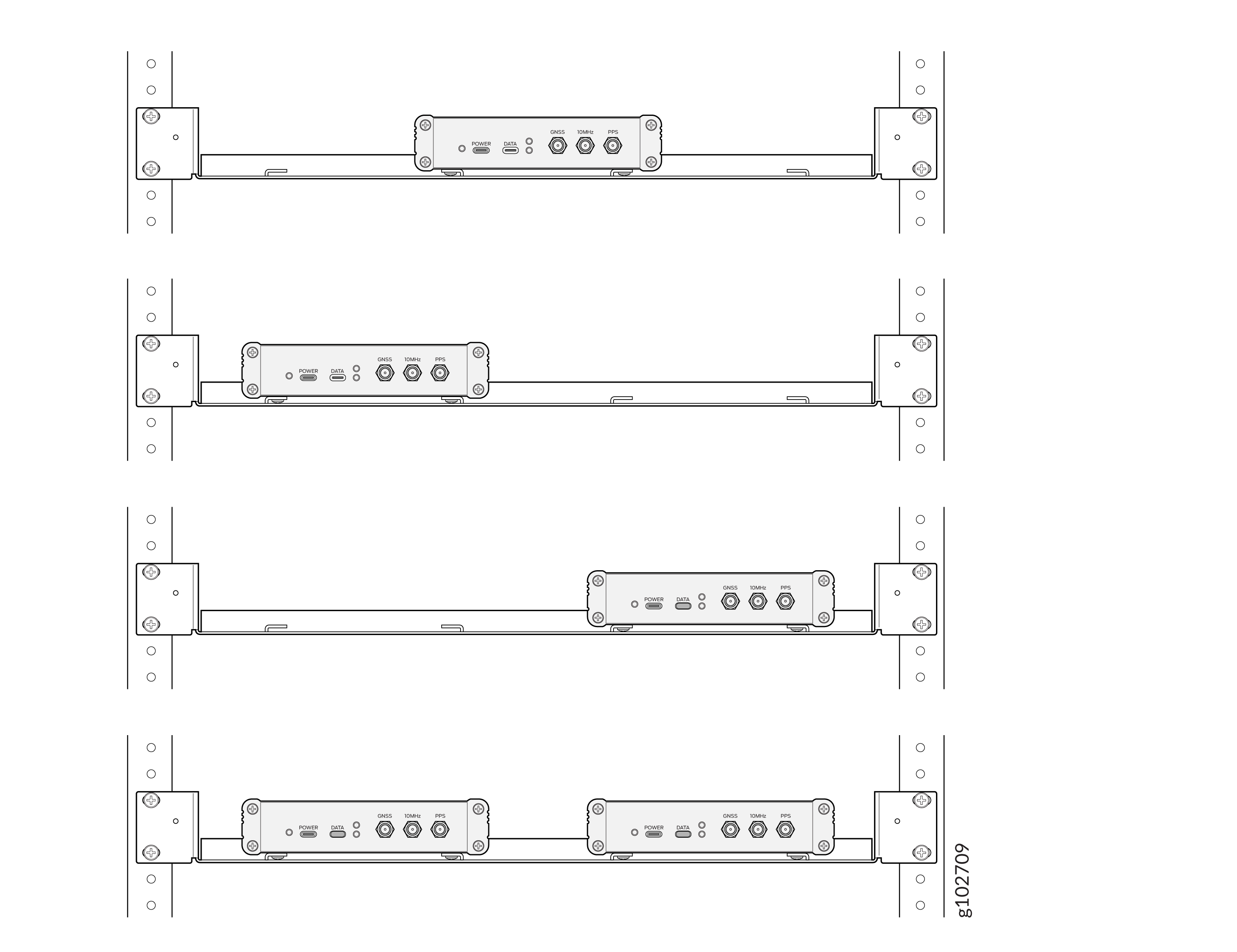
You can install up to two TB-1 receivers on a mounting tray.
To install the TB-1 receiver in a rack, follow the steps given below:
-
Secure the TB-1 receiver to the mounting tray using the four mounting screws (provided).
-
Position the receiver upside down and place the tray (upside down) on the receiver, aligning the threaded holes on the receiver with the holes on the tray.
-
Tighten the mounting screws through the tray into the threaded holes of the receiver.
Figure 2: Secure the Receiver
-
-
Wrap and fasten one end of the ESD grounding strap around your bare wrist, and connect the other end of the strap to a site ESD point.
-
Position the mounting tray in front of the rack. Line up the bottom hole in each mounting bracket with a hole in each rack rail, making sure the mounting tray is level.
-
Secure the mounting tray to the rack using the rack mount screws (not provided). Tighten the screws at the bottom first, then tighten the screws at the top.
Figure 3: Install the Mounting Tray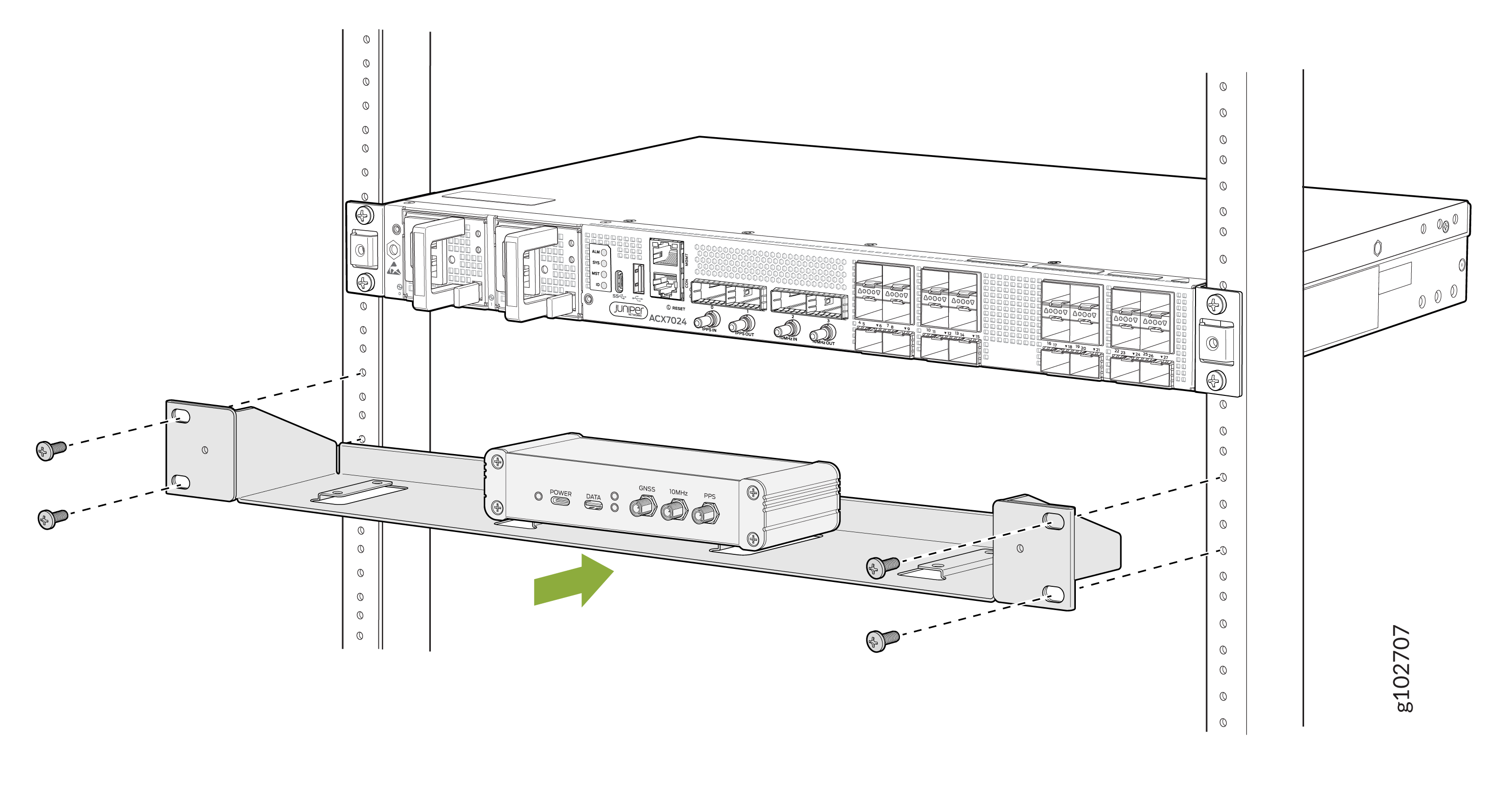
-
Visually inspect the alignment of the mounting tray. Figure 4 shows the TB-1 receiver fully secured and installed in a two-post rack.
Figure 4: TB-1 Receiver Installed on a Rack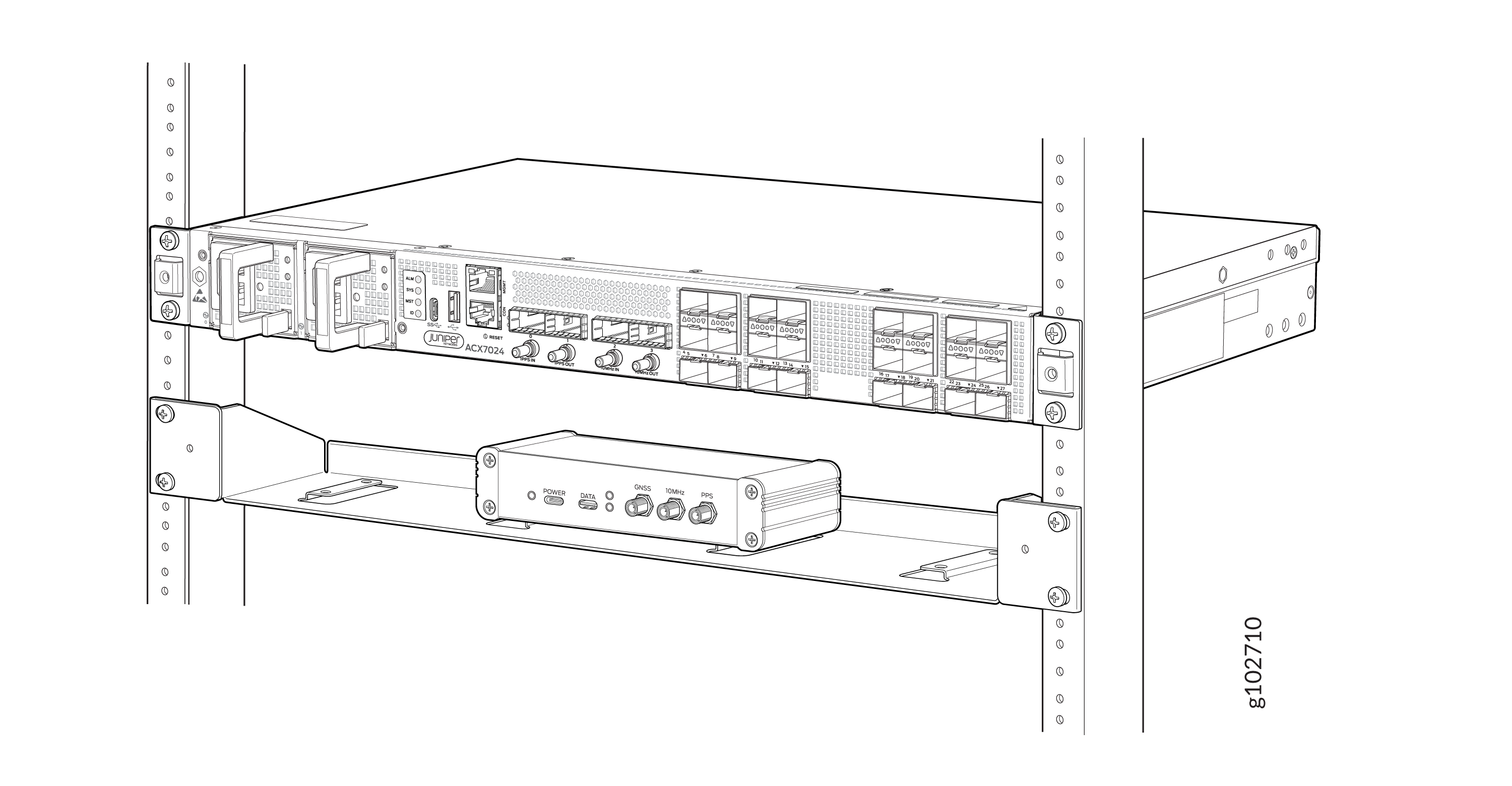
-
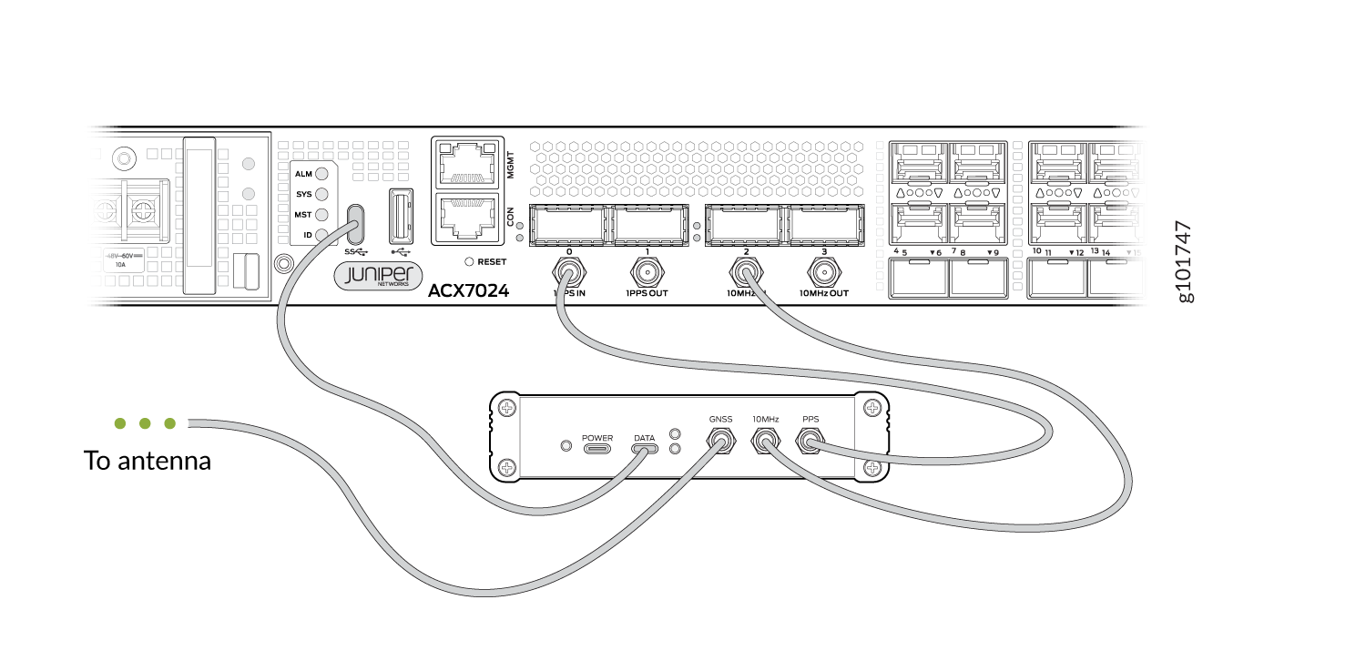
After you have installed the TB-1 receiver, connect the ACX7024 or ACX7024X router to the TB-1 receiver. For more information, see Connect an ACX7024 or ACX7024X Router to the TB-1 Receiver.
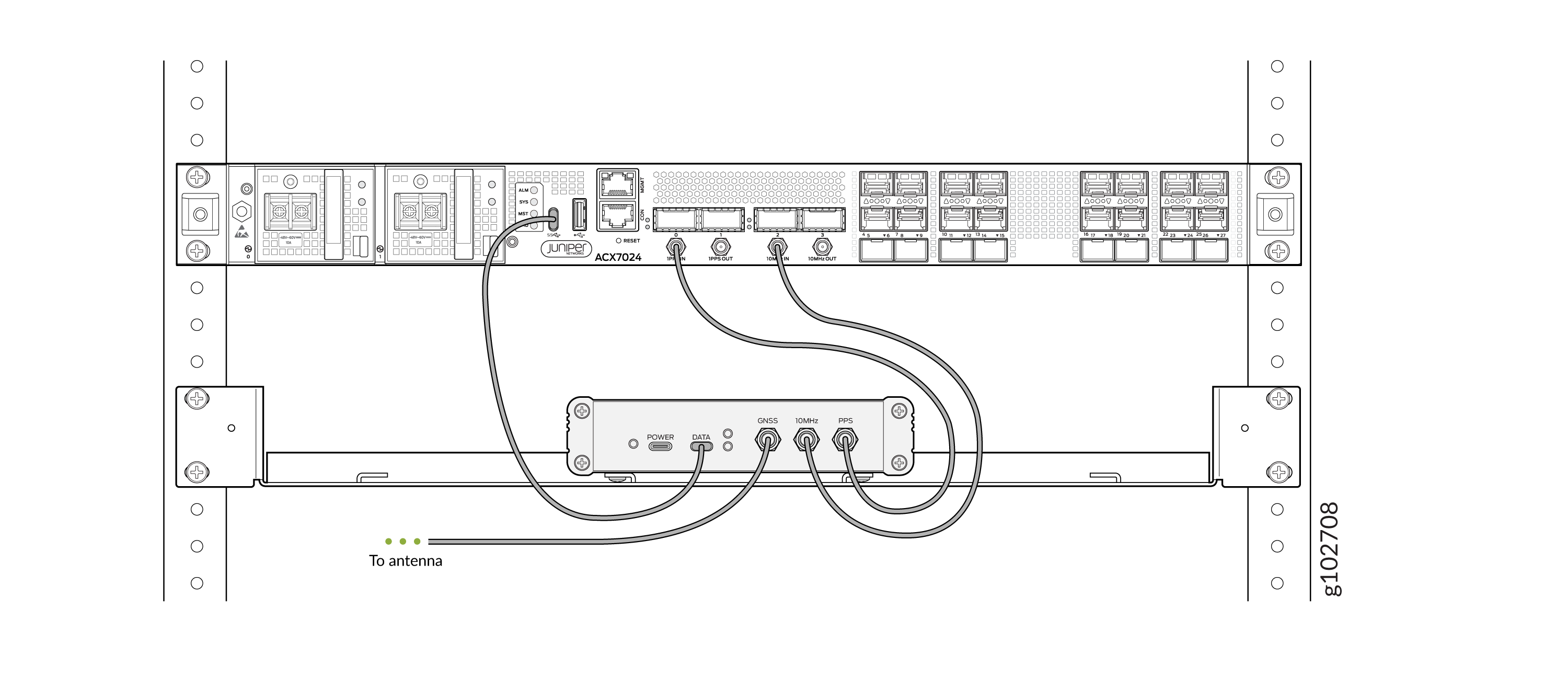
Connect an ACX7024 or ACX7024X Router to the TB-1 Receiver
To connect an ACX7024 or ACX7024X router to a TB-1 receiver:
-
Connect one end of an RG-58 cable to the PPS connector port on the TB-1 receiver (labeled PPS) and the other end of the cable to the 1PPS connector port on the ACX7024 or ACX7024X router (labeled 1PPS IN).
-
Connect one end of an RG-58 cable to the 10-MHz connector port on the TB-1 receiver (labeled 10MHz) and the other end of the cable to the 10-MHz connector port on the ACX7024 or ACX7024X router (labeled 10MHz IN).
Note:The RG-58 cable has an SMA male connector at one end and a DIN 1.0/2.3 connector at the other end. The DIN connector (male) in the RG-58 cable connects to the ACX7024 and ACX7024X router whereas the SMA (male) connector connects to the TB1 receiver.
-
Use a USB-C to USB-C cable to connect one end of the cable to the data port (labeled DATA) on the TB-1 receiver and the other end to the USB type C port on the ACX7024 or ACX7024X router.
-
Connect one end of the LMR400 cable to the GNSS connector port (labeled GNSS) on the TB-1 receiver and the other end to the GNSS antenna.
Install the GNSS Antenna
You must install a Global Navigation Satellite System (GNSS) antenna to ensure optimal signal reception. For information about antenna installation guidelines, see GNSS Antenna Installation in the TB-1 Operation Manual.
To enable the TB-1 receiver, connect to the FURUNO AU-300 antenna. For information about installing the AU-300 antenna, see AU-300 Installation Procedure.
Gain and Noise Figure (NF) Calculation
To calculate the total gain and NF, see GNSS Antenna Installation Appendix on the FURUNO data download page.
