Connect ACX7348 to Power
Learn how to ground the ACX7348 router and connect it to AC and DC power.
Connect Earth Ground to ACX7348 Routers
Before you begin to connect the router to earth ground, ensure that you have the following parts and tools available:
- A grounding cable—6 AWG, 75 °C stranded copper wire (green with yellow insulation)
- Two grounding screws to secure the grounding lug
- LCD6-14A-L grounding lug
- A Phillips (+) screwdriver, number 2 (not provided)
- An electrostatic discharge (ESD) grounding wrist strap (not provided)
To meet safety and electromagnetic interference (EMI) requirements and to ensure proper operation, you must ground the router properly before connecting power.
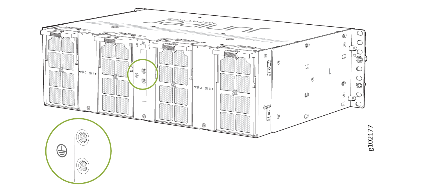
You must install the ACX7348 in a restricted-access location and ensure that the chassis is always properly grounded. The ACX7348 has a two-hole protective grounding terminal provided on rear side of the chassis (see Figure 1). Under all circumstances, use this grounding connection to ground the chassis. For AC-powered systems, you must also use the grounding wire in the AC power cord along with the two-hole grounding lug connection. This tested system meets or exceeds all applicable EMC regulatory requirements with the two-hole protective grounding terminal.
Before you connect earth ground to the protective grounding terminal of an ACX7348 router, ensure that a licensed electrician has attached an appropriate grounding lug to the grounding cable.
To ground the ACX7348 router:
-
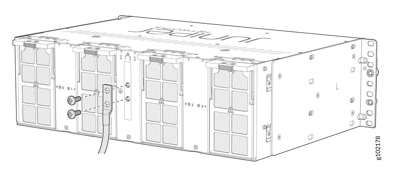
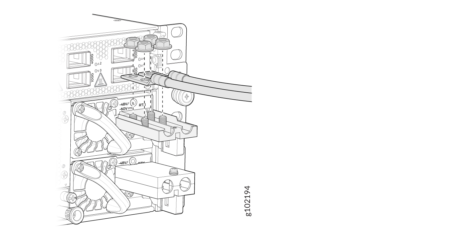
Place the grounding cable lug over the two-hole protective grounding
terminal on the rear side of the chassis (see Figure 2).
Figure 2: Connect the Grounding Cable to the ACX7348 Router
Connect AC Power to an ACX7348 Router
Ensure that you have a power cord appropriate for your geographical location available to connect AC power to the router.
Before you begin connecting AC power to the router:
-
Ensure that you have taken the necessary precautions to prevent electrostatic discharge (ESD) damage (see Prevention of Electrostatic Discharge Damage).
-
Ensure that you have connected the router chassis to earth ground.
CAUTION:Before you connect power to the router, a licensed electrician must attach a cable lug to the grounding and power cables that you supply. A cable with an incorrectly attached lug can damage the router (for example, by causing a short circuit).
To meet safety and electromagnetic interference (EMI) requirements and to ensure proper operation, you must connect the chassis to earth ground before you connect it to power. Under all circumstances, use the protective grounding terminal on the router chassis to connect to the earth ground. The router gains additional grounding when you plug the PSM into the grounded AC power outlet by using the AC power cord appropriate for your geographical location.
-
Install the power supply module (PSM) in the chassis.
The PSM in an ACX7348 router is a hot-removable and hot-insertable field-replaceable unit (FRU). You can remove and replace it without powering off the router or disrupting routing functions.
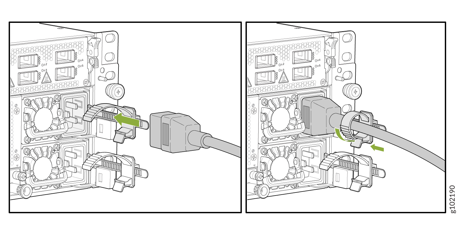
To connect AC power to an ACX7348 router:
Connect DC Power to an ACX7348 Router
Before you begin connecting DC power to the router:
-
Ensure that you have taken the necessary precautions to prevent electrostatic discharge (ESD) damage (see Prevention of Electrostatic Discharge Damage).
-
Ensure that you have connected the router chassis to earth ground.
CAUTION:Before you connect power to the router, a licensed electrician must attach a cable lug to the grounding and power cables that you supply. A cable with an incorrectly attached lug can damage the router (for example, by causing a short circuit).
To meet safety and electromagnetic interference (EMI) requirements and to ensure proper operation, you must connect the chassis to earth ground before you connect it to power. Under all circumstances, use the protective grounding terminal on the router chassis to connect to the earth ground.
-
Install the power supply module (PSM) in the chassis.
Ensure that you have the following parts and tools available:
-
Two DC power source cables. The ACX7348 supports a 6 AWG and 75 °C temperature-rated stranded copper wire.
-
An ESD grounding wrist strap (not provided)
-
Phillips (+) screwdriver, number 2 (not provided) for tightening screws on the PSM terminals.
-
Phillips (+) screwdriver, number 1 (not provided) for tightening the terminal cover screws.
-
Multimeter (not provided)
The PSM in an ACX7348 router is a hot-removable and hot-insertable field-replaceable unit (FRU). You can remove and replace it without powering off the router or disrupting routing functions.
To connect DC power to an ACX7348 router:
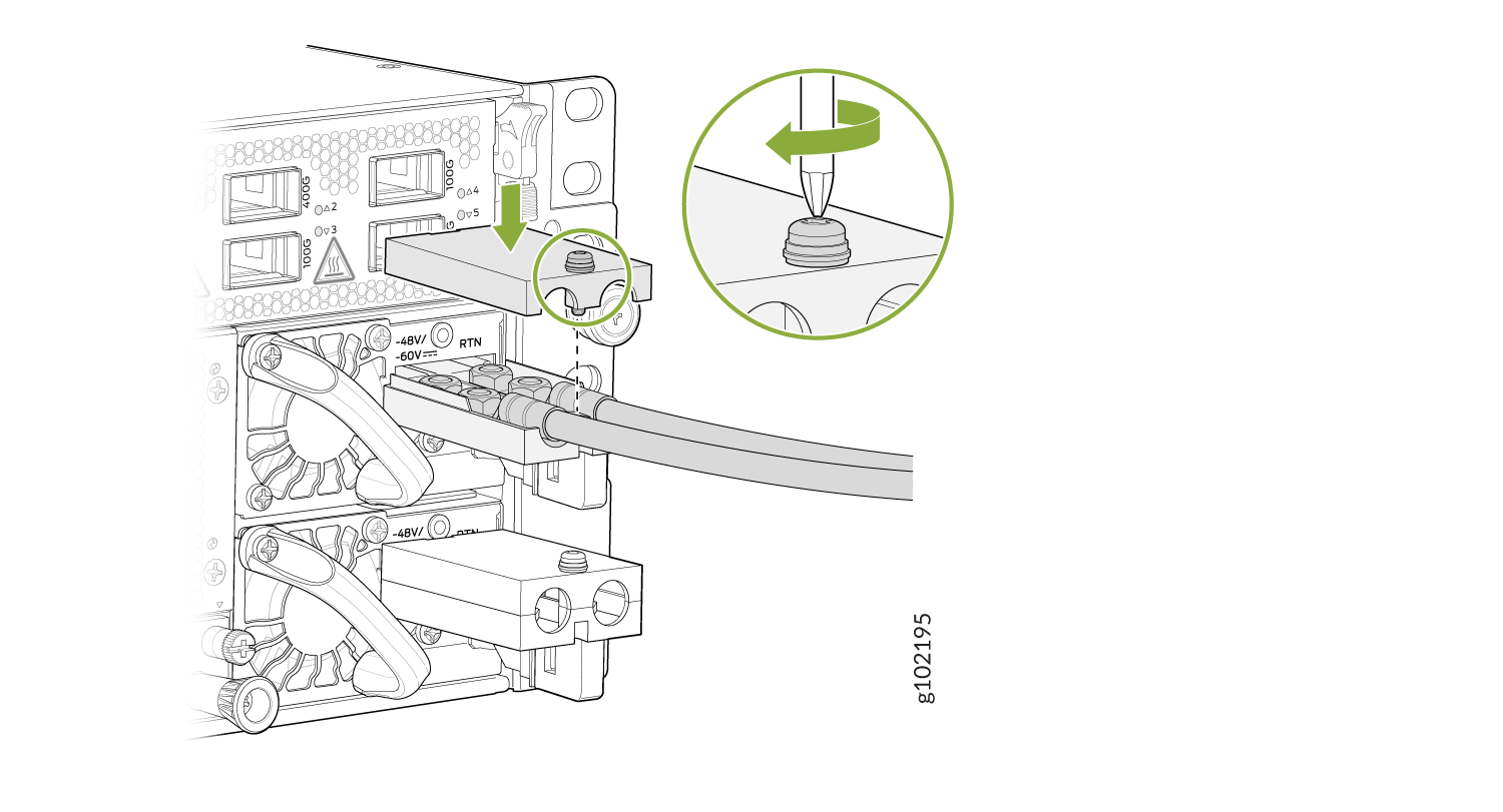
-
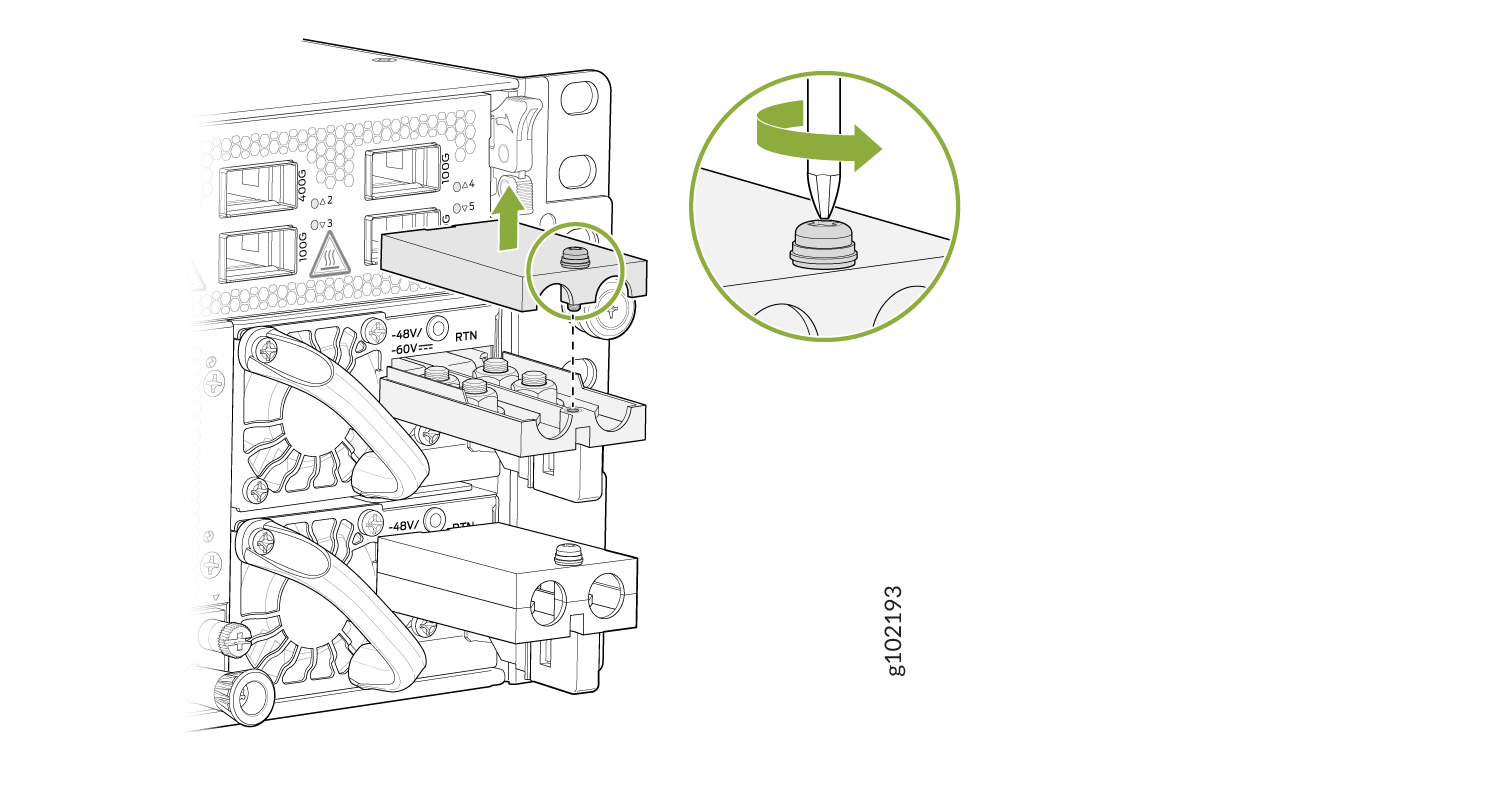
Using a screwdriver, unscrew (counterclockwise) the nut on top of the
terminal block.
Figure 4: Remove the Terminal Block Cover
-
Install heat-shrink tubing insulation around the power
cables.
To install heat-shrink tubing:
-
Slide the tubing over the portion of the cable where it is attached to the lug barrel. Ensure that the tubing covers the end of the wire and the barrel of the lug is attached to it.
-
Shrink the tubing with a heat gun. Ensure that you heat all sides of the tubing evenly so that it shrinks around the cable tightly.
Figure 5 shows the steps to install heat-shrink tubing.
Note:Do not overheat the tubing.
Figure 5: How to Install Heat-Shrink Tubing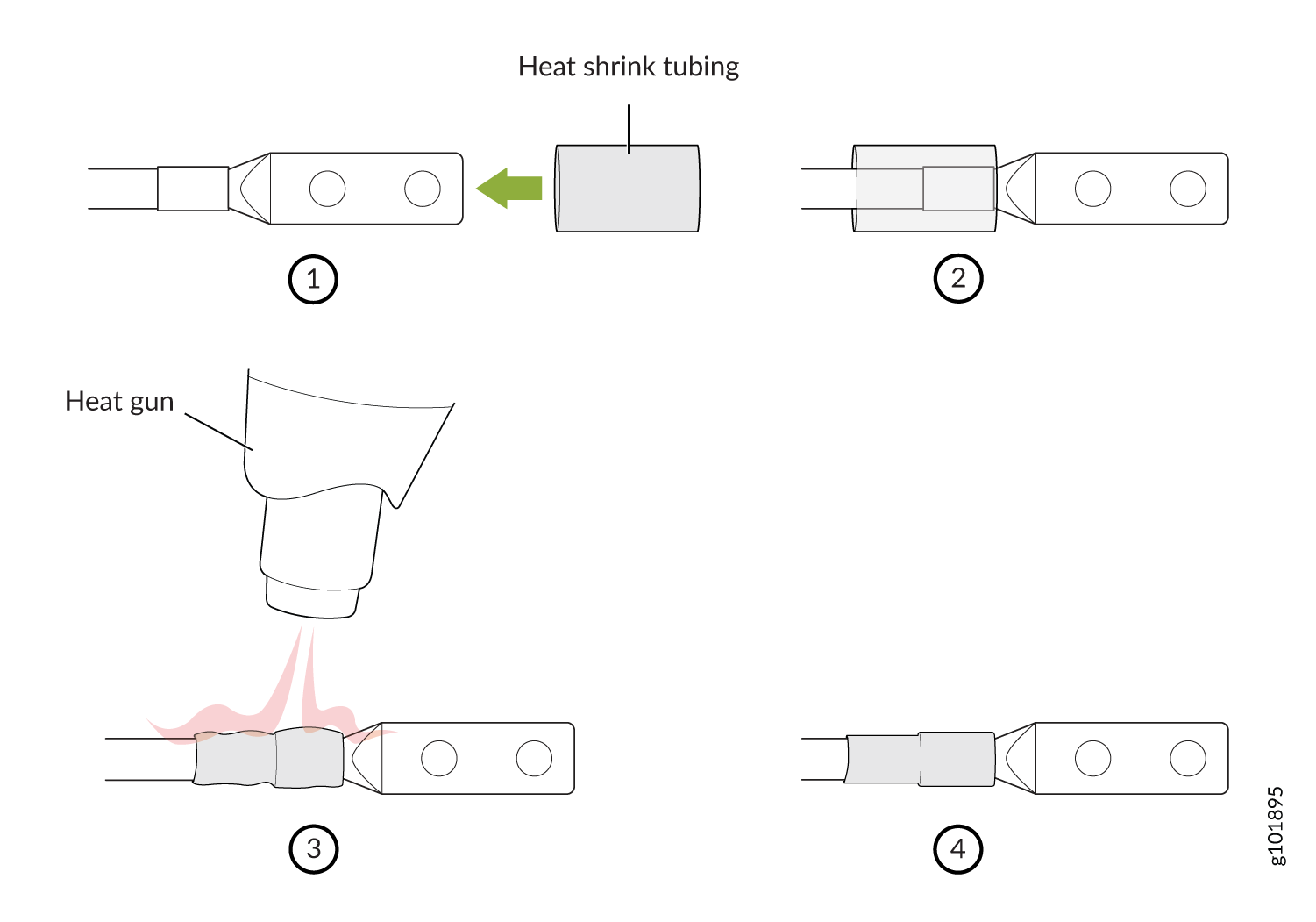
-
-
Remove the nuts from the four terminals in the terminal block. See Figure 6.
Figure 6: Remove the Nuts from the Terminals
-
Secure each power cable lug to the terminal with the nuts. Tighten the nuts
on the power supply terminals until snug by using the screwdriver. Do not
apply vertical force while tightening the screws. Use a socket nut driver to
ensure you don't overtighten the nuts.
Figure 7: Connect the DC Cable
 Note:
Note:To connect the DC source to an ACX7348 router, use a 6 AWG and 75 °C temperature-rated stranded copper wire.
-
Secure the positive (+) DC source power cable lug to the RTN (return) terminal.
-
Secure the negative (–) DC source power cable lug to the –48V/-60V (input) terminal.
CAUTION:Ensure that each power cable lug seats flush against the surface of the terminal block as you are tightening the nuts. Ensure that each nut is properly threaded into the terminal. Applying installation torque to the nuts when improperly threaded can result in damage to the terminal.
CAUTION:You must ensure that power connections maintain the proper polarity. The power source cables might be labeled (+) and (–) to indicate their polarity. There is no standard color coding for DC power cables. The color coding used by the external DC power source at your site determines the color coding for the leads on the power cables that attach to the terminal studs on each power supply.
-