EX4000 Chassis
Chassis Physical Specifications for EX4000 Switches
The EX4000 switch chassis is a rigid sheet-metal structure that houses all components of the switch.
|
Model |
Chassis Height |
Chassis Width |
Chassis Depth |
Chassis Weight |
|---|---|---|---|---|
|
EX4000-8P |
1.75 in (4.44 cm) |
10.39 in (26.40 cm) |
9.64 in (24.5 cm) |
5.73 lb (2.60 Kg) |
|
EX4000-12T |
1.75 in (4.44 cm) |
10.39 in (26.40 cm) |
9.64 in (24.5 cm) |
5.07 lb (2.30 Kg) |
|
EX4000-12P |
1.75 in (4.44 cm) |
10.39 in (26.40 cm) |
9.99 in (25.37 cm) |
7.05 lb (3.2 Kg) |
|
EX4000-12MP |
1.75 in (4.44 cm) |
10.39 in (26.40 cm) |
9.99 in (25.37 cm) |
6.94 lb (3.2 Kg) |
|
EX4000-24P |
1.71 in (4.34 cm) |
17.36 in (44.10 cm) |
10.16 in (25.8 cm) |
9.2 lb (4.2 Kg) |
|
EX4000-24T |
1.71 in (4.34 cm) |
17.36 in (44.10 cm) |
8.43 in (21.40 cm) |
6.3 (2.9 Kg) |
|
EX4000-24MP |
1.71 in (4.34 cm) |
17.36 in (44.1 cm) |
10.16 in (25.80 cm) |
9.3 lb (4.1 Kg) |
|
EX4000-48P |
1.71 in (4.34cm) |
17.36 in (44.10 cm) |
11.97 in (30.40 cm) |
10.8 lb (4.9 Kg) |
|
EX4000-48T |
1.71 in (4.34 cm) |
17.36 in (44.10 cm) |
10.16 in (25.8 cm) |
7.9 lb (3.6 Kg) |
|
EX4000-48MP |
1.71 in (4.34 cm) |
17.36 in (44.1 cm) |
11.97 in (30.40 cm) |
11.68 lb (5.3 Kg) |
Chassis Status LEDs on EX4000 Switches
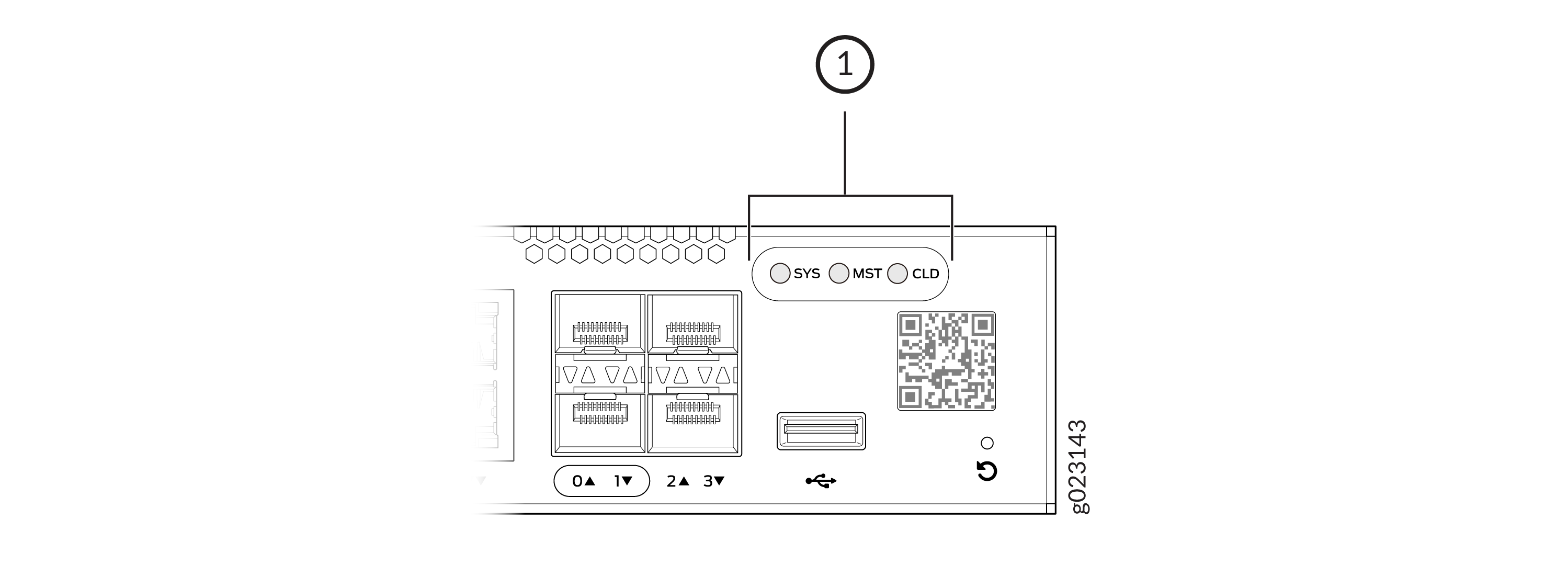
EX4000 switches have three chassis status LEDs (labeled SYS, MST, and CLD) on the front panel.

1 — Chassis status LEDs |
Table 2 describes the system chassis status LED labeled as SYS on an EX4000 switch when in standalone mode.
Table 3 describes the system chassis status LED labeled as SYS on an EX4000 switch when in Virtual Chassis mode.
|
LED Label |
Color |
State and Description |
|---|---|---|
|
SYS |
Blinking green |
Switch is booting up. |
|
Solid green |
Switch has booted up. No alarms. |
|
|
Amber |
Minor Alarm |
|
|
Red |
Major Alarm |
|
|
Blue |
Appears on short press of Pin Hole Reset button. See Revert to the EX Series Switch Factory-Default Configuration or Zeroize the Switch Using Pin Hole Reset Button. |
|
|
Purple |
Appears on long press of Pin Hole Reset button. See Revert to the EX Series Switch Factory-Default Configuration or Zeroize the Switch Using Pin Hole Reset Button. |
|
LED Label |
Virtual Chassis Member and LED Color |
State and Description |
||
|---|---|---|---|---|
|
Master |
Backup |
Linecard |
||
|
SYS |
Green |
Green |
Green |
No alarms |
|
Red or Amber |
Green |
Green |
Alarm present on master member |
|
|
Red or Amber |
Red or Amber |
Green |
Alarm present on backup member |
|
|
Red or Amber |
Green |
Red or Amber |
Alarm present on linecard member |
|
Table 4 describes the chassis status LED labeled MST when the switch is in standalone mode.
Table 5 describes the chassis status LED labeled MST when the switch is in virtual chassis mode.
You can view the colors of the LEDs remotely through the CLI by issuing the
show chassis led operational mode command.
|
LED Label |
Color |
State and Description |
|---|---|---|
|
MST |
Green |
In a standalone switch:
|
|
LED Label |
Virtual Chassis Member |
Color |
State and Description |
|---|---|---|---|
|
MST |
Master |
Green |
Likewise, the number of times the LED blinks before pausing is equal to its FPC number in the VC. |
|
Backup |
Yellow |
Likewise, the number of times the LED blinks before pausing is equal to its FPC number in the VC. |
|
|
Linecard |
White |
Likewise, the number of times the LED blinks before pausing is equal to its FPC number in the VC. |
For information on the blink patterns of the CLD LED, which provide the cloud connection status of the switch, see Cloud Ready LED Blink Pattersor see Cloud Ready Connection Process to understand how the cloud connection works.
LEDs on the Management Port on EX4000 Switches
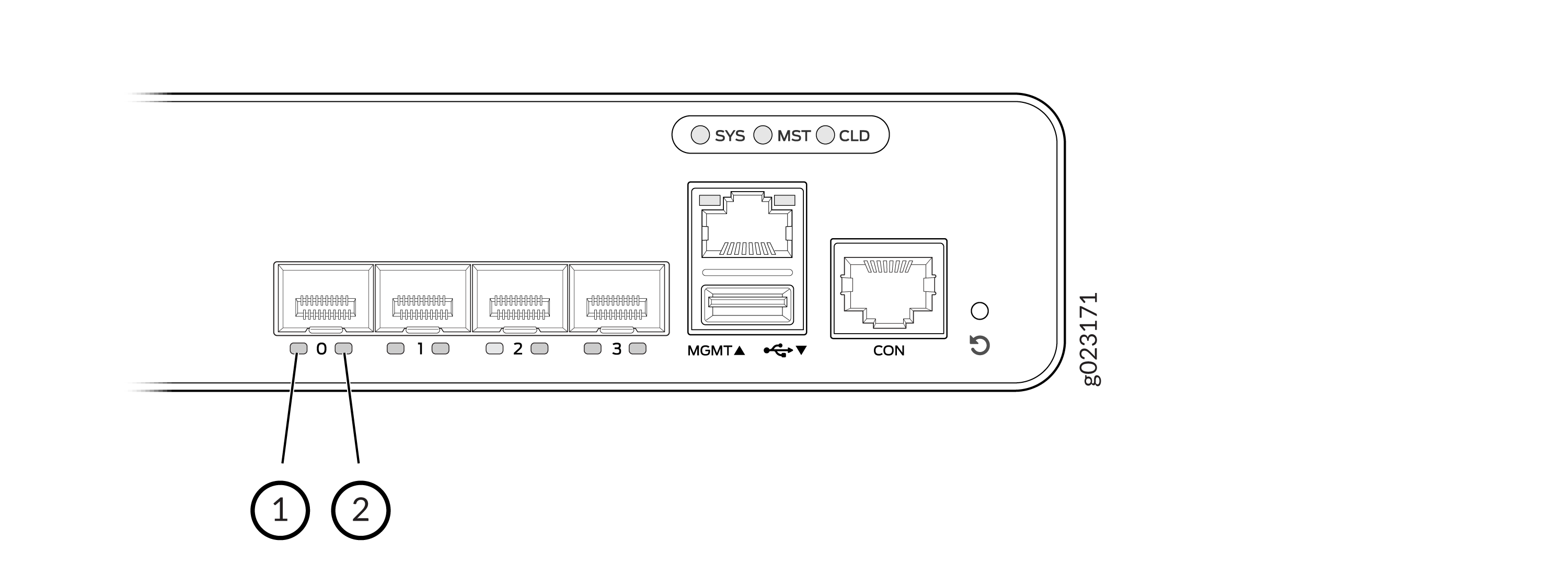
The management port, labeled MGMT, located on the front panel of the EX4000-8P, EX4000-12T, EX4000-12P, and EX4000-12MP switch and the rear panels of EX4000-24P, EX4000-24T, EX4000-24MP, EX4000-48P, EX4000-48T and EX4000-48MP switches has two LEDs that indicate link activity and port status (see Figure 2).

1 — Link activity LED | 2 — Status LED |
Table 6 describes the LEDs.
|
LED |
Color |
State and Description |
|---|---|---|
|
Link activity |
Green |
|
|
Status |
Green |
Indicates the speed:
|
LEDs on the RJ-45 Network Ports, Virtual Chassis Ports/Uplink Ports on EX4000 Switches
The RJ-45 network ports, and SFP+ uplink ports/Virtual Chassis ports on EX4000 switches have LEDs that show the link activity and port status.
LEDs on the Network Ports
The figures in this section show and describe the LEDs on the following ports:
-
Figure 3 shows the LEDs on the RJ-45 network ports on EX4000 switches. Table 7 details the Link Activity LED and Link Status LED descriptions on the 100-Mbps/1-Gbps/2.5-Gbps network/downlink ports.

1 — Link activity LED | 2 — Status LED |
|
LED |
Color |
State and Description |
|---|---|---|
|
Link activity |
Green |
|
|
Status |
Green or Amber |
|
LEDs on the SFP+ Virtual Chassis/uplink ports
The figures in this section show and describe the LEDs on the following ports:
-
Figure 4 hows the LEDs on the SFP+ Virtual Chassis/uplink ports on EX4000-8P.
Table 8 details the Link Activity LED and Link Status LED descriptions on the 1-Gbps/10-Gbps Virtual Chassis/uplink ports ports.
-
Figure 5 shows the LEDs on the SFP+ Virtual Chassis/uplink ports on EX4000-12T, EX4000-12P, and EX4000-12MP.
Table 8 details the Link Activity LED and Link Status LED descriptions on the 1-Gbps/10-Gbps Virtual Chassis/uplink ports ports.
-
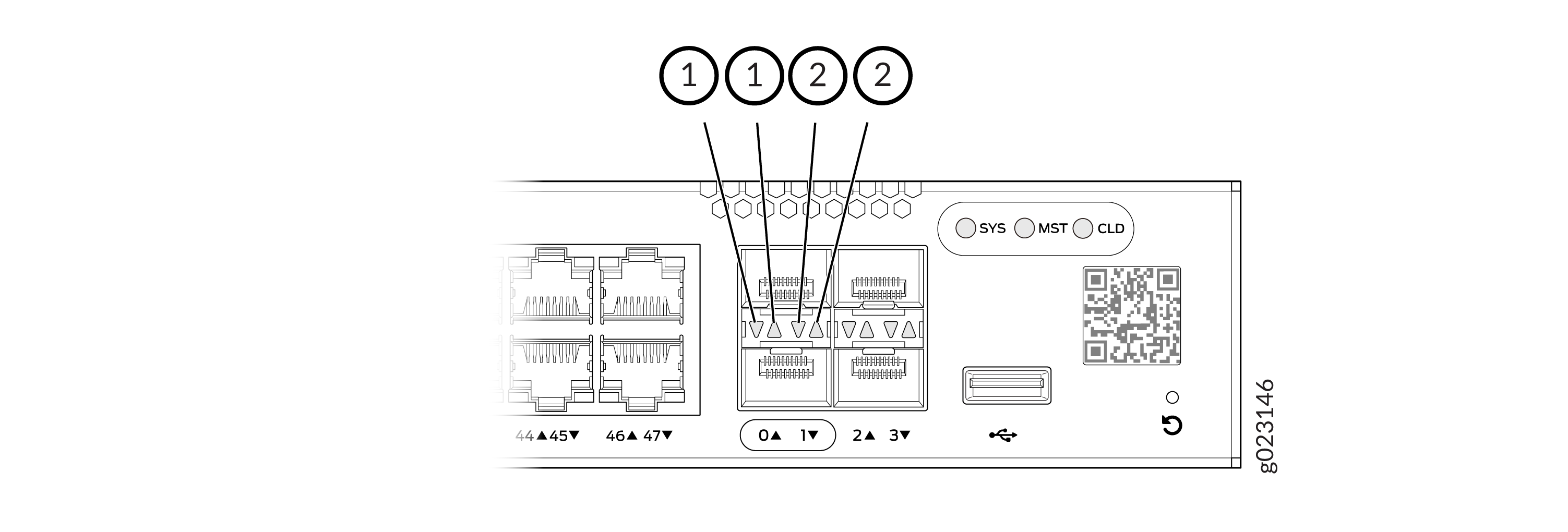
Figure 6 shows the LEDs on the SFP+ Virtual Chassis/uplink ports on EX4000-24P, EX4000-24T, EX4000-48P, EX4000-48T, EX4000-24MP, and EX4000-48MP switches.
Table 8 details the Link Activity LED and Link Status LED descriptions on the 1-Gbps/10-Gbps Virtual Chassis/uplink ports ports.


1 — Link activity LED | 2 — Status LED |
|
LED |
Color |
State and Description |
|---|---|---|
|
Link activity |
Green |
|
|
Status |
Green |
|
