Cooling System and Airflow in an EX4100-F Switch
The cooling system in EX4100-F switch consists of fanless models and models with built-in fan(s). EX4100-F-12P and EX4100-F-12T switch models are fanless and rely on natural convection cooling. The airflow direction depends on the fan modules and power supplies installed in the switch.
Airflow Direction in EX4100-F Switch Models
Table 1 shows the direction of airflow in EX4100-F models as shipped.
|
Model Number |
Fan Modules and Power Supply |
Direction of Airflow |
|---|---|---|
|
One built-in fan with AFO cooling. |
Front-to-back—cold air to cool the chassis enters through the vents on the front panel of the chassis, and hot air exits through the vents on the rear panel of the chassis. |
|
Two built-in fans with AFO cooling. |
Front-to-back—cold air to cool the chassis enters through the vents on the front panel of the chassis, and hot air exits through the vents on the rear panel of the chassis. |
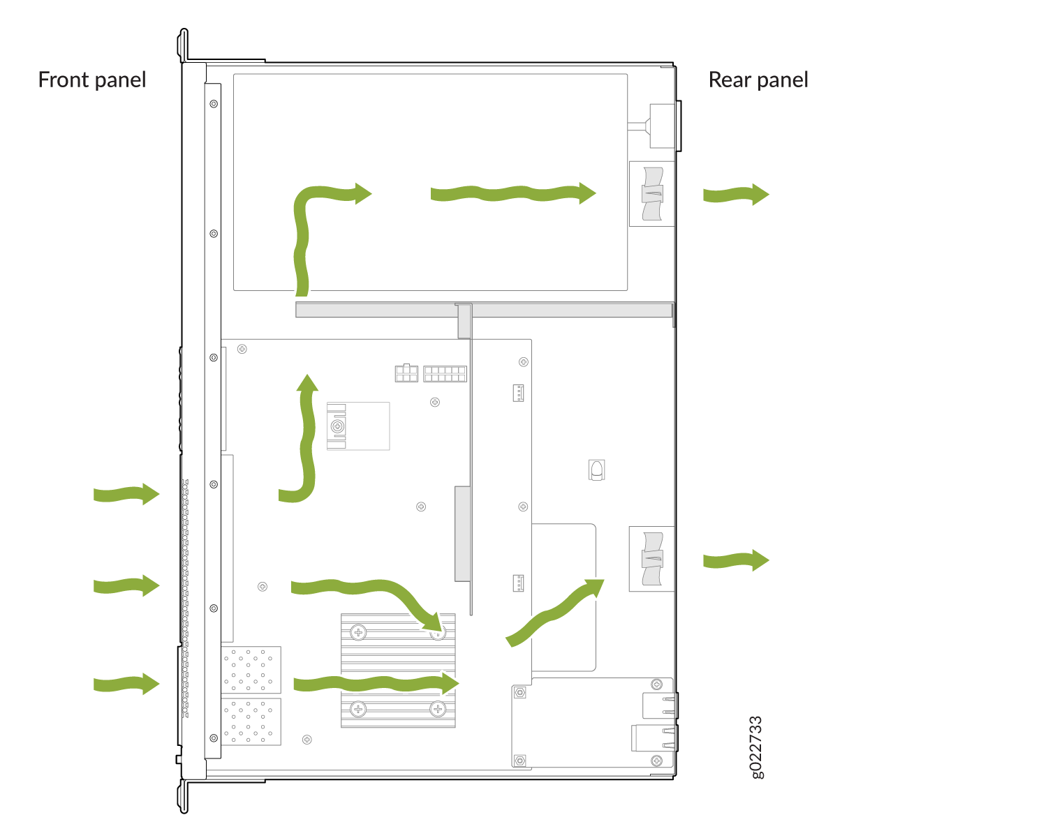
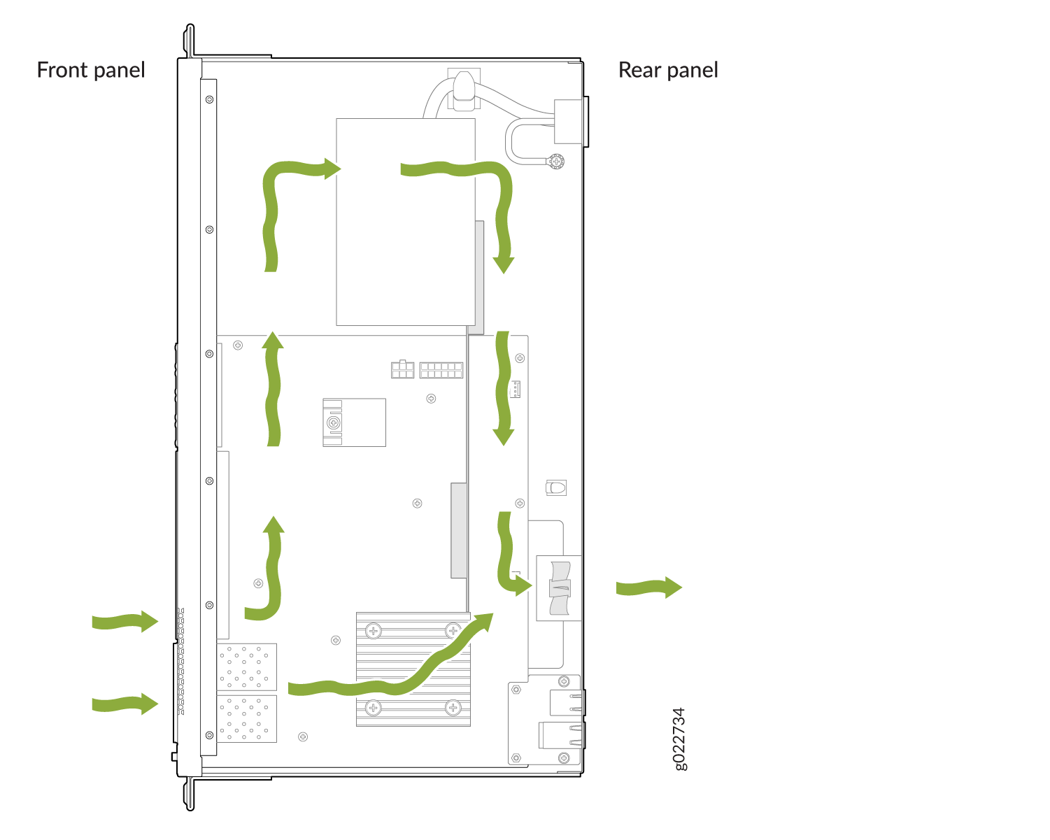
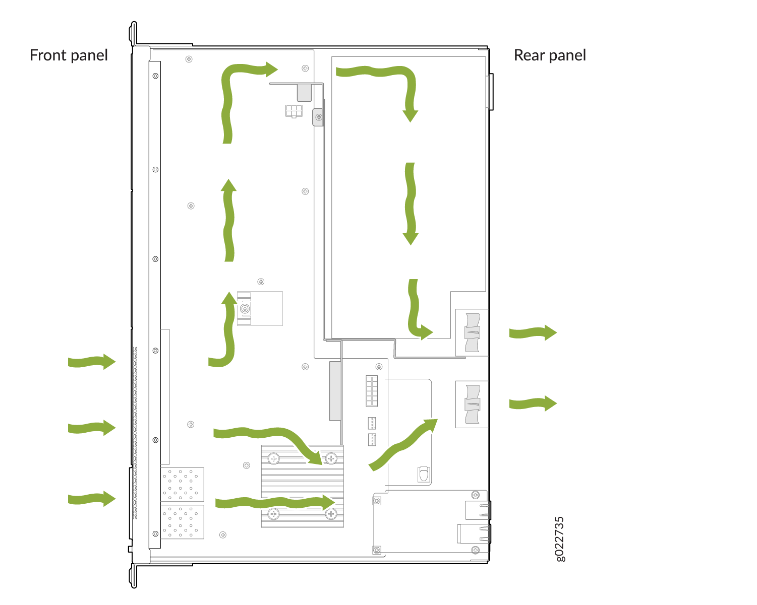
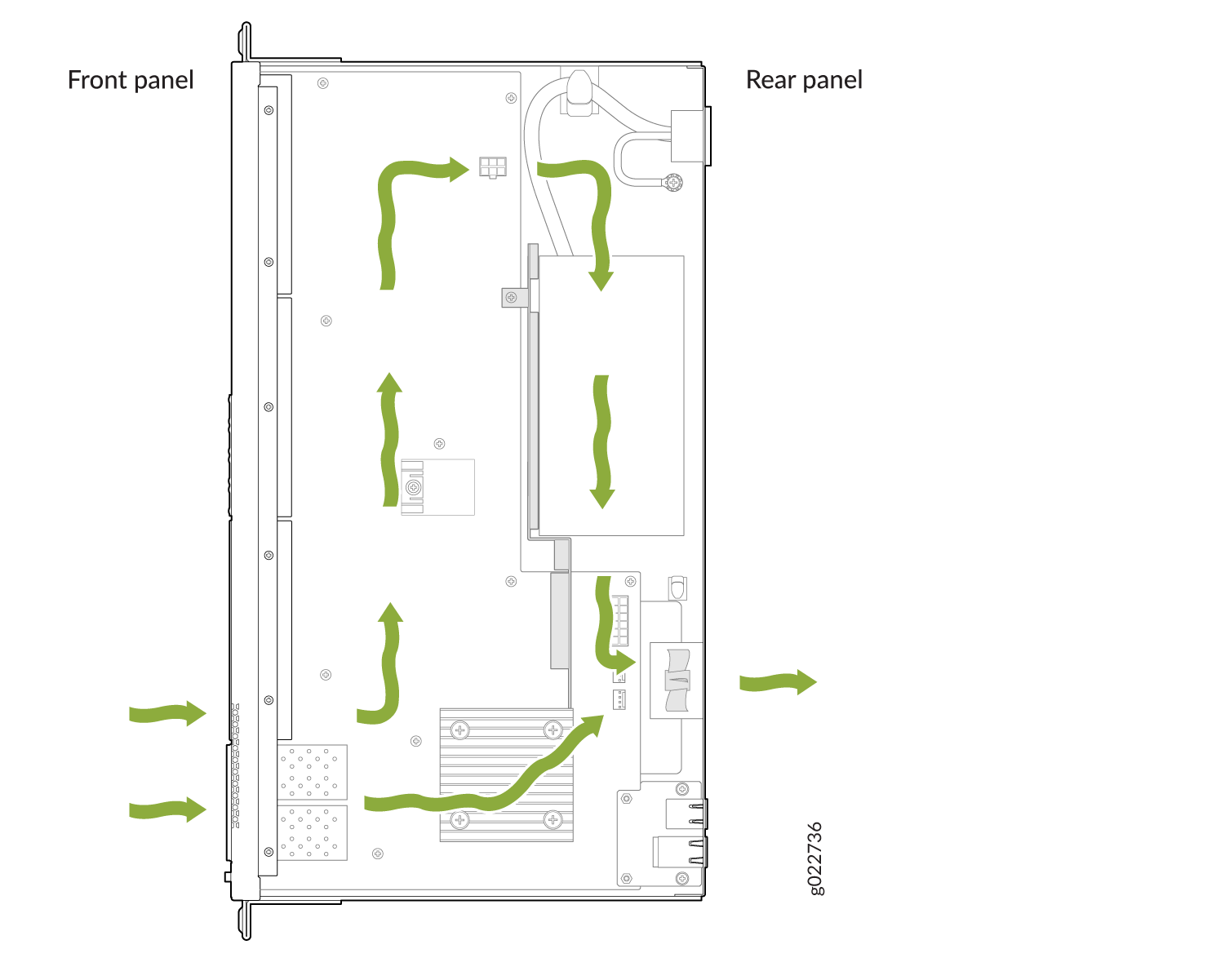
EX4100-F Switches with Front-to-Back Airflow
In EX4100-F switch models with front-to-back airflow, air enters through vents on the front panel to cool the chassis. The hot air then exits through the vents on the rear panel.
The front side of a switch is the side where the ports are located. The rear side is where the fans are located.
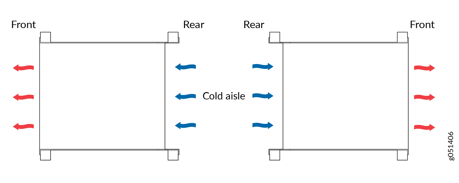
How to Position the Switch
Position the switch with front-to-back airflow in such a manner that the AIR OUT labels on the fan modules and power supplies are next to the hot aisle (see Figure 5).
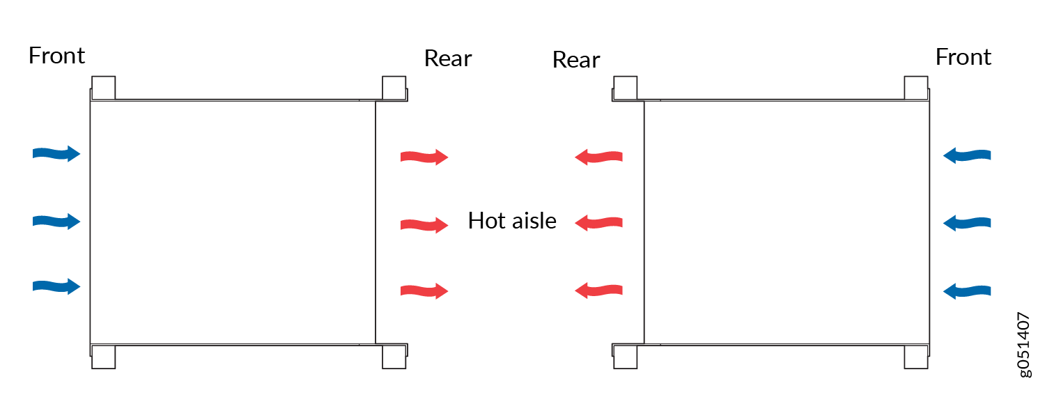
Position the switch with back-to-front airflow in such a manner that the AIR IN labels on the fan modules and power supplies are next to the cold aisle (see Figure 6).