EX4100-F Chassis
Chassis Physical Specifications for EX4100-F Switches
The EX4100-F switch chassis is a rigid sheet-metal structure that houses all components of the switch.
|
Model |
Chassis Height |
Chassis Depth |
Chassis Width |
Chassis Weight with Power Supply and Fan Module |
|
|---|---|---|---|---|---|
|
EX4100-F-24T |
1.72 in (4.37 cm) |
10.1 in (25.65 cm) |
17.36 in (44.09 cm) |
3520g |
|
|
EX4100-F-24P |
1.72 in (4.37 cm) |
12.26 in (31.13 cm) |
17.36 in (44.09 cm) |
4745g |
|
|
EX4100-F-48P |
1.72 in (4.37 cm) |
12.26 in (31.13 cm) |
17.36 in (44.09 cm) |
5200g |
|
|
EX4100-F-48T |
1.72 in (4.37 cm) |
10.1 in (25.65 cm) |
17.36 in (44.09 cm) |
3885g |
|
|
Model |
Chassis Height |
Chassis Depth |
Chassis Width |
Chassis Weight |
|---|---|---|---|---|
|
EX4100-F-12P |
1.75 in (4.44 cm) |
9.66 in (24.54 cm) |
10.59 in (26.9 cm) |
3000g |
|
EX4100-F-12T |
1.75 in (4.44 cm) |
9.66 in (24.54 cm) |
10.59 in (26.9 cm) |
2700g |
|
Model |
Power Supply Adaptor (w) |
Height |
Width |
Depth |
Weight |
|---|---|---|---|---|---|
|
EX4100-F-12P |
280 |
1.77 in (4.5 cm) |
3.93 in (10 cm) |
7.87 in (20 cm) |
1350g |
|
EX4100-F-12T |
75 |
1.43 in (3.65 cm) |
2.63 in (6.7 cm) |
6.10 in (15.5 cm) |
2700g |
|
Sound Pressure (Acoustics) |
|||
|---|---|---|---|
|
Switch Model |
Power Supply |
LpA (dB) Typical 1PSU/2PSU |
Max 1PSU/2PSU |
|
EX4100-F-24T |
65W AC AFO |
NA |
35.4 |
|
EX4100-F-24P |
450W AC AFO |
40.1 |
45.1 |
|
EX4100-F-48T |
90W AC AFO |
NA |
37.1 |
|
EX4100-F-48P |
850 AC AFO |
46.2 |
46.5 |
Chassis Status LEDs on EX4100-F Switches
EX4100-F switches have four chassis status LEDs (labeled SYS, ALM, MST, and CLD) on the rightside of the front panel .
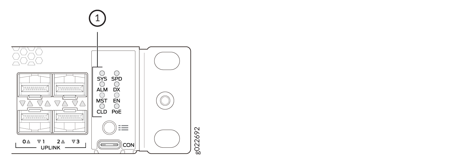
1 — Chassis status LEDs |
Table 5 describes the chassis status LEDs labeled
SYS, ALM, and
MST on an EX4100-F switch. The table also describes their
colors and states and the status each LED indicates. You can view the colors of the
LEDs remotely through the CLI by issuing the show chassis led
operational mode command. All LEDs can be lit simultaneously.
For information on the blink patterns of the CLD LED, which provide the cloud connection status of the switch, see Cloud Ready LED Blink Patterns or see Cloud Connection Process to understand how the cloud connection works.
|
LED Label |
Color |
State and Description |
|---|---|---|
|
SYS |
Green |
|
|
Unlit |
The switch is powered off or is halted. |
|
|
ALM |
Red |
A major hardware fault—such as a temperature alarm or a power failure alarm—occurred, and the switch is halted. A major alarm indicates a critical error condition that requires immediate attention (see Chassis Component Alarm Conditions on EX4100-F Switches). |
|
Amber |
A minor alarm—such as a software or a hardware error—occurred. Power off the switch and then power it back on. Monitor the switch to see whether it is working properly. A minor alarm indicates a non-critical condition that requires monitoring or maintenance. A minor alarm that is left unchecked might cause interruption in service or performance degradation. |
|
|
Unlit |
No alarm is in effect, or the switch is halted. |
|
|
MST |
Green |
In a standalone switch:
|
|
In a Virtual Chassis configuration:
|
When issuing show system alarms, only the ALM LED of the master
switch in a virtual chassis system glows to display the alarm state. Backup
switch and linecard ALM LEDs will be unlit. However, when issuing show
chassis alarms, ALM LED glows on all of the individual member
switches, displaying their individual alarm states.
For Virtual Chassis deployments managed from the cloud, the CLD LED on individual Virtual Chassis members will reflect the state of the Master, except when a software download is in progress. When a software download is in progress, the CLD LED on a Virtual Chassis member will display the Junos OS upgrading LED pattern and color.
LEDs on the Management Port on EX4100-F Switches
The management port, labeled MGMT, on the rear panel of EX4100-F switches has two LEDs that indicate link activity and port status.
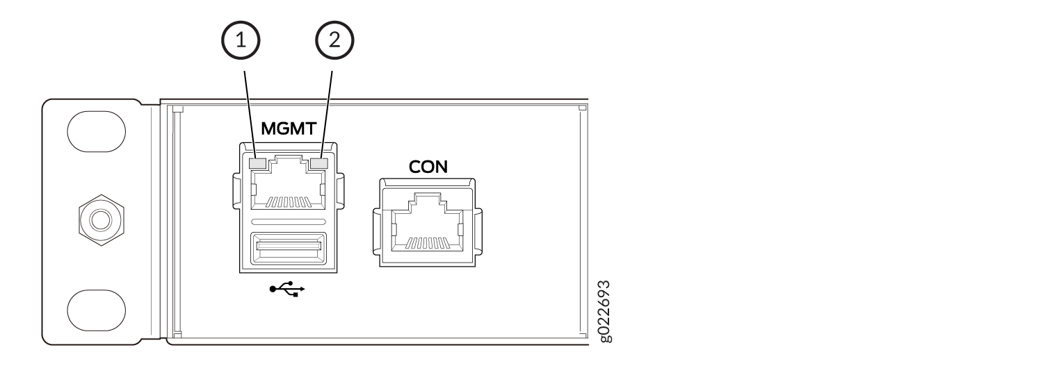
1 — Link activity LED | 2 — Status LED |
The following table describes the LEDs.
|
LED |
Color |
State and Description |
|---|---|---|
|
Link activity |
Green |
|
|
Status |
Green |
Indicates the speed:
|
LEDs on the RJ-45 Network Ports, Virtual Chassis Ports, and Uplink Ports on EX4100-F Switches
The RJ-45 network ports, SFP+ uplink ports, and SFP+/SFP28 Virtual Chassis Ports on EX4100-F switches have LEDs that show the link activity and port status.
LEDs on the Network Ports
The figures in this section show and describe the LEDs on the following ports:
-
Figure 3 shows the LEDs on the RJ-45 network ports on EX4100-F switches.
-
Figure 4 shows the LEDs on the SFP+ uplink ports.
-
Figure 5 shows the LEDs on the SFP+/SFP28 Virtual Chassis Ports.
-
Table 7 describes the link activity LED state and description on the RJ-45 ports, SFP+ uplink ports, and SFP+/SFP28 Virtual Chassis Ports.
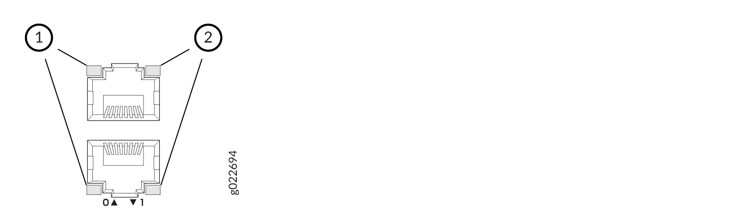
1 — Link activity LED | 2 — Status LED |
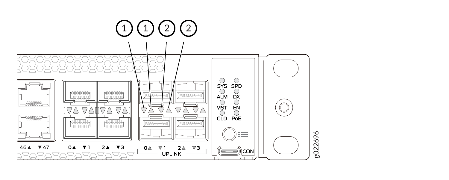
1 — Link activity LED | 2 — Status LED |
The status LEDs on the port number 24 - 47 will be updated with a delay which varies from 1 second to 9 seconds when a cable is plugged or unplugged.
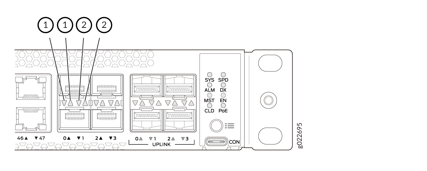
1 — Link activity LED | 2 — Status LED |
|
Link Activity LED Color |
Link Status LED State and Description |
|---|---|
|
Green |
|
EX4100-F switches have network port mode LEDs (labeled SPD, DX, EN, and POE) on the right side of the front panel (see Figure 6.) These LEDs indicate the status of the network ports. Use the mode button on the right side of the front panel to toggle the status LEDs. You toggle the status LEDs to show the different port parameters for the network ports. The LED that is lit indicates the port parameter. Table 8 describes the status LEDs.
The LED labeled PoE is not available on switch models with network ports that do not provide PoE.
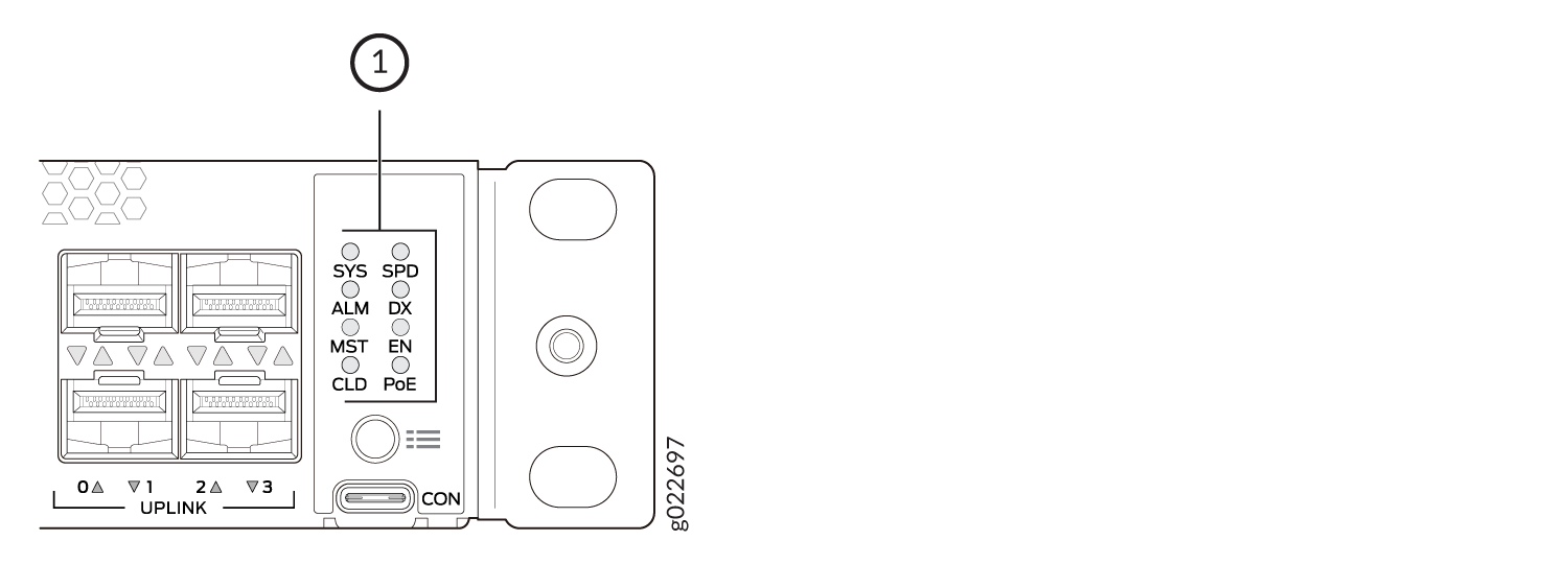
1 — Port Mode LEDs |
|
LED |
Color |
State and Description |
|---|---|---|
|
SPD |
Green |
Indicates the speed. The speed indicators are as follows:
|
|
DX |
Green |
Indicates the duplex mode. The status indicators are as follows:
|
|
EN |
Green |
Indicates the administrative status. The status indicators are as follows:
|
|
POE |
Green |
Indicates the PoE mode. The status indicators are as follows:
|