Connect the EX4100-F Switch to External Devices
Connect a Device to a Network for Out-of-Band Management
Ensure that you have an Ethernet cable that has an RJ-45 connector at either end.
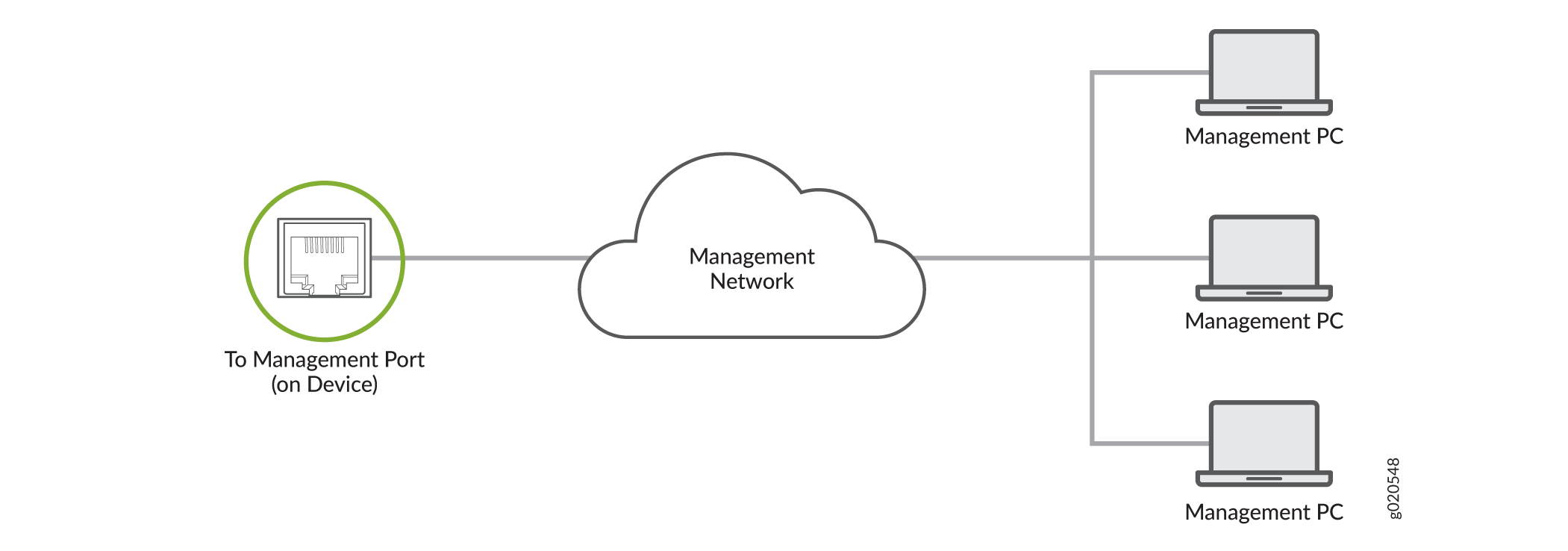
You can monitor and manage a network device, such as a router or a switch, by using a dedicated management channel. Each device has a management port to which you can connect an Ethernet cable with an RJ-45 connector. Use the management port to connect the device to the management device.
To connect a device to a network for out-of-band management:
- Connect one end of the Ethernet cable to the management port on the device.
- Connect the other end of the Ethernet cable to the management device.
Connect a Device to a Management Console Using an RJ‑45 Connector
Ensure that you have an Ethernet cable that has an RJ-45 connector at either end and an RJ-45-to-DB-9 serial port adapter.
- RJ-45 to DB-9 adapter (JNP-CBL-RJ45-DB9)
- RJ-45 to USB-A adapter (JNP-CBL-RJ45-USBA)
- RJ-45 to USB-C adapter (JNP-CBL-RJ45-USBC)
If you want to use RJ-45 to USB-A or RJ-45 to USB-C adapter, you must have X64 (64-Bit) Virtual COM port (VCP) driver installed on your PC. See https://ftdichip.com/drivers/vcp-drivers/ to download the driver.
If your laptop or desktop PC does not have a DB-9 plug connector pin and you want to connect your laptop or desktop PC directly to the device, use a combination of the RJ-45-to-DB-9 socket adapter and a USB-to-DB-9 plug adapter. You must provide the USB-to-DB-9 plug adapter.
You can configure and manage your network devices using a dedicated management channel. Each device has a console port that you can connect to using an Ethernet cable with an RJ-45 connector. Use the console port to connect the device to the console server or management console. The console port accepts a cable that has an RJ-45 connector.
To connect the device to a management console:
- Connect one end of the Ethernet cable to the console port (labeled CON, CONSOLE, or CON1) on the device.
- Connect the other end of the Ethernet cable to the console server (see Figure 3) or management console (see Figure 4).


Connect an EX4100-F Switch to a Management Console Using the USB Type-C Console Port
Before You Begin
Before you connect the switch using the USB Type-C console port:
-
Ensure that the USB to serial driver is installed on the host machine.
-
Ensure that the HyperTerminal properties of the console server or laptop are set as follows:
-
Baud rate—9600
-
Flow control—None
-
Data—8
-
Parity—None
-
Stop bits—1
-
DCD state—Disregard
-
You will need:
-
One USB cable with USB Type-C connectors at both ends (not provided).
-
(If your laptop or desktop PC does not have a USB Type-C port) One USB Type-A to USB Type-C converter cable (not provided).
EX4100-F switches have two console ports:
-
An RJ-45 console port on the rear panel that accepts a cable with an RJ-45 connector
-
A USB Type-C console port on the front panel that accepts a USB cable with a USB Type-C connector
You can log in to the switch and configure and manage the switch by using either of the console ports. The RJ-45 console port is enabled by default. However, you must configure the USB Type-C console port before you can use it to connect to the switch.
In this topic, you learn how to connect EX4100-F switches to the management console using the USB Type-C console port.
To connect the switch to the console using the USB Type-C console port: