EX4100-F Power System
AC Power Supply in EX4100-F Switches
- Characteristics of AC Power Supply in EX4100-F Switches
- Specifications of the AC Power Supplies Used in EX4100-F Switches
- PoE Budget Planning
- Specifications of the Power Cord for AC Power Supplies for EX4100-F Switches
Characteristics of AC Power Supply in EX4100-F Switches
-
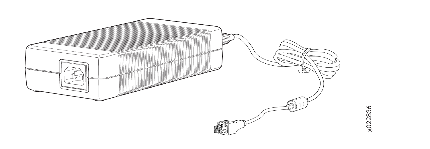
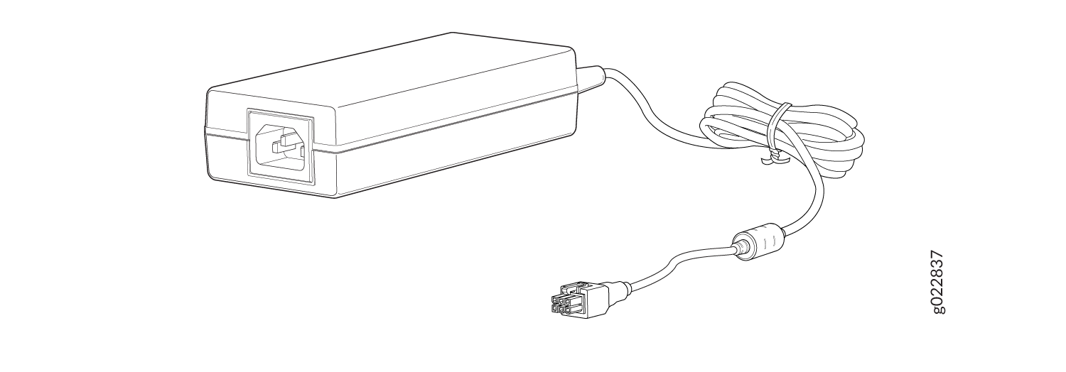
The EX4100-F-12P and EX4100-F-12T switches use the 280-W and 75-W external power adapters respectively.
-
EX4100-F-24P, EX4100-F-24T, EX4100-F-48P, and EX4100-F-48T use built-in 450-W, 65-W, 850-W, and 90-W, AC power supplies respectively. The built-in AC power supplies support Power over Ethernet (PoE+) in EX4100-F-24P and EX4100-F-48P switch models.
Refer Table 1 to check which EX4100-F models use which built-in power supplies.
Specifications of the AC Power Supplies Used in EX4100-F Switches
-
Table 1 provides the power supply specifications of the built-in AC Power Supplies in EX4100-F switches.
|
Item |
Specification |
|---|---|
|
850 W |
|
|
450 W |
|
|
90 W |
|
|
65 W |
|
PoE Budget Planning
Table 2 shows the PoE Budget Planning Details of EX4100-F-12P Switches. Table 3 shows the PoE budget planning details in EX4100-F-24P and EX4100-F-48P switch models.
|
Power Source |
|||||
|---|---|---|---|---|---|
|
External adapter (280 W) |
PoE++ PSE (power supply equipment) (90 W) |
PoE++ PSE (60 W) |
PoE+ PSE (30 W) |
Connected to how many uplink ports |
Total PoE budget (W) |
|
Y |
- | - | - | - |
180 |
| - |
Y |
- | - |
1 |
0 |
| - |
Y |
- | - |
2 |
60 |
|
Y |
Y |
- | - |
1 |
240 |
|
Y |
Y |
- | - |
2 |
300 |
| - | - |
Y |
- |
2 |
30 |
|
Y |
- |
Y |
- |
1 |
225 |
|
Y |
- |
Y |
- |
2 |
270 |
|
Y |
- | - |
Y |
1 |
200 |
|
Y |
- | - |
Y |
2 |
220 |
Apart from the aforementioned combinations, any other combination will be insufficient to power the switch.
|
Model |
System Budget |
PoE Budget |
Total Budget |
Total PSU power |
|---|---|---|---|---|
|
F-48P |
87 W |
740 W |
827 W |
850 W |
|
F-24P |
73 W |
370 W |
443 W |
450 W |
Specifications of the Power Cord for AC Power Supplies for EX4100-F Switches
A detachable AC power cord is supplied with the AC power supplies. The coupler is type C13 as described by International Electrotechnical Commission (IEC) standard 60320. The plug end of the power cord fits into the power source outlet that is standard for your geographical location.
The AC power cord provided with each power supply is intended for use with that power supply only and not for any other use.
In North America, AC power cords must not exceed 4.5 meters (approximately 14.75 feet) in length, to comply with National Electrical Code (NEC) Sections 400-8 (NFPA 75, 5-2.2) and 210-52 and with Canadian Electrical Code (CEC) Section 4-010(3). The cords supplied with the switch are in compliance.
Table 4 gives the AC power cord specifications for the countries and regions listed in the table.
|
Country or Region |
Electrical Specifications |
Plug Standards |
Juniper Model Number |
|---|---|---|---|
|
Argentina |
250 VAC, 10 A, 50 Hz |
IRAM 2073 Type RA/3 |
CBL-EX-PWR-C13-AR |
|
Australia |
250 VAC, 10 A, 50 Hz |
AS/NZZS 3112 Type SAA/3 |
CBL-EX-PWR-C13-AU |
|
Brazil |
250 VAC, 10 A, 50 Hz |
NBR 14136 Type BR/3 |
CBL-EX-PWR-C13-BR |
|
China |
250 VAC, 10 A, 50 Hz |
GB 1002-1996 Type PRC/3 |
CBL-EX-PWR-C13-CH |
|
Europe (except Italy, Switzerland, and the United Kingdom) |
250 VAC, 10 A, 50 Hz |
CEE (7) VII Type VIIG |
CBL-EX-PWR-C13-EU |
|
India |
250 VAC, 10 A, 50 Hz |
IS 1293 Type IND/3 |
CBL-EX-PWR-C13-IN |
|
Israel |
250 VAC, 10 A, 50 Hz |
SI 32/1971 Type IL/3G |
CBL-EX-PWR-C13-IL |
|
Italy |
250 VAC, 10 A, 50 Hz |
CEI 23-16 Type I/3G |
CBL-EX-PWR-C13-IT |
|
Japan |
125 VAC, 12 A, 50 Hz or 60 Hz |
JIS 8303 |
CBL-EX-PWR-C13-JP |
|
Korea |
250 VAC, 10 A, 50 Hz or 60 Hz |
CEE (7) VII Type VIIGK |
CBL-EX-PWR-C13-KR |
|
North America* |
125 VAC, 13 A, 60 Hz |
NEMA 5-15 Type N5-15 |
CBL-EX-PWR-C13-US |
|
125 VAC, 15 A, 60 Hz |
NEMA 5-15 Type N5-15 |
CBL-PWR-C13-US-48P |
|
|
South Africa |
250 VAC, 10 A, 50 Hz |
SABS 164/1:1992 Type ZA/13 |
CBL-EX-PWR-C13-SA |
|
Switzerland |
250 VAC, 10 A, 50 Hz |
SEV 6534-2 Type 12G |
CBL-EX-PWR-C13-SZ |
|
United Kingdom |
250 VAC, 10 A, 50 Hz |
BS 1363/A Type BS89/13 |
CBL-EX-PWR-C13-UK |
For North America, use AC power cords with specifications for EX4100-F-48P.
Figure 3 illustrates the plug on the power cord for some of the countries or regions listed in Table 4.
Do not use the AC power cord with any other product other than EX4100-F.
Power cords must not block access to switch components.
Table 5 lists the specifications of the power cords used to connect EX4400 switches to C13 Power Strips.
|
Country/Region |
Electrical Specifications |
Juniper Model Number |
|---|---|---|
|
USA, China, Japan, Europe, South Korea, Australia |
250 VAC, 10 A, 50 Hz |
CBL-EX-PWR-C13-C14 |