ON THIS PAGE
Fast Track to Rack Installation and Power
This procedure guides you through the simplest steps for the most common installation to mount your MX10008 router in a rack and connect it to power. Have more complex installation needs? See Mount the Juniper Networks MX10008 Router Using the JNP10K-RMK-4PST-XT Rack-Mount Kit.
Install the MX10008 in a Rack
You can mount an MX10008 router in a four-post closed-frame rack or a four-post open-frame rack by using the JNP10004-RMK-4POST rack mount kit (shipped with the router by default) or the JNP10K-RMK-4PST-XT rack mount kit. We'll walk you through the steps to install an MX10008 router by using the JNP10004-RMK-4POST rack mount kit and connect it to power.
The router chassis weighs approximately 145 lb (66 kg) with only the fan tray controllers installed.
You can mount an MX10008 router manually or by using a mechanical lift. Because of the router's size and weight, we strongly recommend that you use a mechanical lift to mount the MX10008.
Ensure that you have a mechanical lift rated for 500 lb (226.8 kg).
You must install the router in a restricted-access location and ensure that the chassis is always grounded properly.
Before you install, review the following:
Mount the Router
To mount the MX10008 router on a four-post rack:
Place the router on a flat, stable surface.
Wrap and fasten one end of the ESD grounding strap around your bare wrist, and connect the other end to a site ESD point.
Attach the mounting blades to the front rack posts by using six rack mount screws appropriate for your rack and a screwdriver.
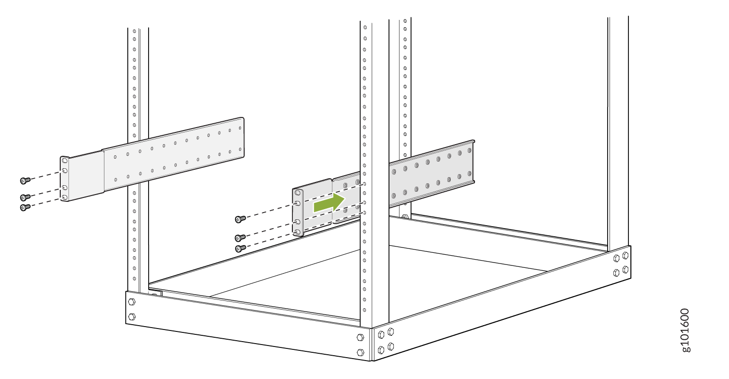
From the rear of the rack, slide the mounting tray into the rear posts of the rack such that the mounting blades slide into the grooves on the mounting tray. Attach the tray to the rear rack posts by using eight rack-mount screws appropriate for your rack .
Check that the mounting tray is level.
Attach the mounting blades to the tray with the 12 Phillips 8-32 x .375 in. flat-head screws.
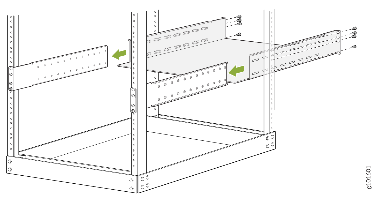
Load the router onto the lift, making sure that it rests securely on the lift platform.

Using the lift, align the router in front of the rack, centering it in front of the mounting tray.
Lift the chassis approximately 0.75 in. (1.9 cm) above the surface of the mounting tray. Align the chassis as close as possible to the mounting tray.
Carefully slide the chassis onto the mounting tray until the chassis flanges contact the rack rails. The mounting blades ensure that the holes in the chassis flanges line up with the holes in the rack rails.
Starting at the bottom, attach the chassis to the rack by inserting 14 rack mount screws through each open flange hole and rack hole.

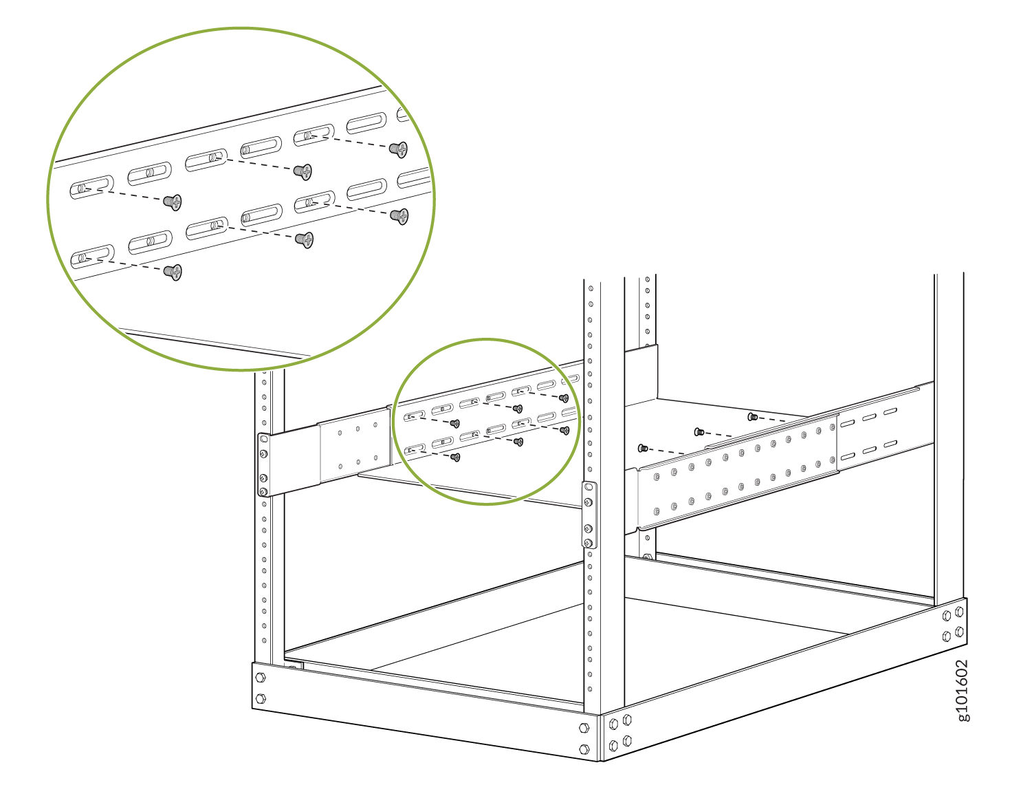
Move the lift away from the rack.
Check the alignment of the router. The mounting screws on each side of the rack should line up, and the router should be level. Tighten the screws.
Insert the safety restraint between the rear posts of the rack. It should rest on the top of the chassis and align with the holes in the rack.
Attach the restraint to the rack by inserting six mounting screws through each open flange hole and rack hole. Tighten the screws.
Connect to Power
The MX10004 router supports AC, DC, high-voltage alternating current (HVAC), and high-voltage direct current (HVDC). In this guide, we show you how to connect AC power.
To connect the MX10008 to AC power:
Install the Power Supplies
To install the JNP10K-PWR-AC2 power supply in an MX10008 router:
If the power supply slot has a cover panel on it, insert your thumb and forefinger into the finger holes, squeeze and pull the cover out of the slot. Save the cover panel for later use.

Taking care not to touch power supply connections, remove the power supply from its bag.
Peel back and remove the protective plastic wrap that covers all four sides of the power supply.
Ensure the power router is set to the standby (O) position. This router turns off the output voltage; it does not interrupt input power.
Unscrew the captive screw in the counterclockwise direction by using the Phillips (+) screwdriver, number 1.
Rotate the captive screw away from the faceplate of the power supply to release the latch.
Note:You can install the power supplies in any slot labeled PSU 0 through PSU 5 (top to bottom).
Using both hands, place the power supply in the power supply slot on the rear of the system. Slide the power supply straight into the chassis until the power supply is fully seated in the slot. Ensure the power supply faceplate is flush with any adjacent power supply faceplates or power supply cover panels.

Push the captive screw into the power supply faceplate. Ensure that the screw is seated inside the corresponding hole on the faceplate.
Tighten the captive screw by turning it clockwise by using the Phillips (+) screwdriver, number 1. When the screw is completely tight, the latch locks into the router chassis.
Ground the Router
To meet safety and electromagnetic interference (EMI) requirements and to ensure proper operation, you must connect the chassis to earth ground. Make this connection before you connect the router to power.
To connect the MX10008 router to earth ground:
Verify that a licensed electrician has attached the cable lug (provided in the accessory kit) to the grounding cable.
Connect the other end of the grounding cable to a proper earth ground, such as the rack in which the router is mounted.
Attach an ESD grounding strap to your bare wrist, and connect the strap to the ESD grounding point next to the earthing posts.
Figure 1: ESD Point on the MX10008 Chassis Rear 1—
1—ESD point
Remove the two screws on the chassis using a Phillips screwdriver.
Place the chassis grounding lug and cable over the PEM nuts with the cable connection pointing to the left.

Place the two screws over the grounding lug and grounding cable.
Tighten the two 10-32 screws using a Phillips screwdriver applying torque between of 30.1 in.-lb (3.4 N-m) and 42.04 in.-lb (4.75 N-m).
Dress the grounding cable and ensure that it does not touch or block access to other device components and that it does not drape where people could trip over it.
Connect the Power Cable and Power On the Router
To connect the power cable and power on the MX10008 router:
Attach each power cable to a dedicated power source (A and B). The JNP10K-PWR-AC2 requires that each power supply be connected to a separate source. See Figure 2 for some possible cabling combinations for MX10008.
Figure 2: Proper Load Balancing for JNP10K-PWR-AC2 Power Cables
For each power cable, insert the end of the cable with the Anderson connector into the JNP10K-PWR-AC2 power supply module. The connector snaps and locks the cable into position.
Warning:Ensure that the power cords do not block access to router components or drape where people can trip on them.
If the power source outlets have a power switch, set them to the on (|) position.
Set the three DIP switches to set the inputs and whether the power supply is running at 3000 W, 5000 W, or 5500 W. See Table 1.
Set both enable switches to the on position when using both source inputs; power is shared equally. When not using source redundancy, set the unused source to the O (off) position. The LED turns red and indicates an error if a source input is not in use and the enable switch is | (on).
Table 1: Setting the JNP10K-PWR-AC2 DIP Switches Switch
State
Field
1
On
INP1 (INP0 in CLI output) is present
Off
INP1 is not present.
2
On
INP2 (INP1 in CLI output) is present.
Off
INP2 is not present.
3
On
Enabled for 30 A feed; 5500 W for a single feed, 5000 W for dual feeds.
Off
Enabled for 20 A feed; power supply capacity is 3000 W.
Verify that the INP1 and INP2 LEDs on the power supply faceplate are lit and are on steadily.
Press the power switch to the on (|) position.