Fast Track to Rack Installation and Power
This procedure guides you through the simplest steps for the most common installation to get your MX204 router in a rack and connect it to power.
Install the MX204 Router in a Rack
You can install the MX204 router in a standard 19-in. rack. We'll walk you through the steps to install an AC-powered router in a four-post rack.
Before you install, review the following:
If you're installing more than one router in a rack, install them from the bottom up.
Before mounting the router in a rack, have a qualified technician verify that the rack is strong enough to support the router's weight and is adequately supported at the installation site.
Position the router in front of the rack or cabinet.
Attach an electrostatic discharge (ESD) grounding strap to your bare wrist and to a site ESD point.
Align the holes in the front mounting brackets with the holes on the side of the chassis as shown:
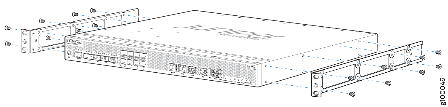
Using a Phillips (+) number 2 screwdriver, secure the mounting brackets to the router using the mounting screws.
With one person on each side, hold on to the bottom of the chassis and carefully lift it so that the mounting brackets contact the rack rails.
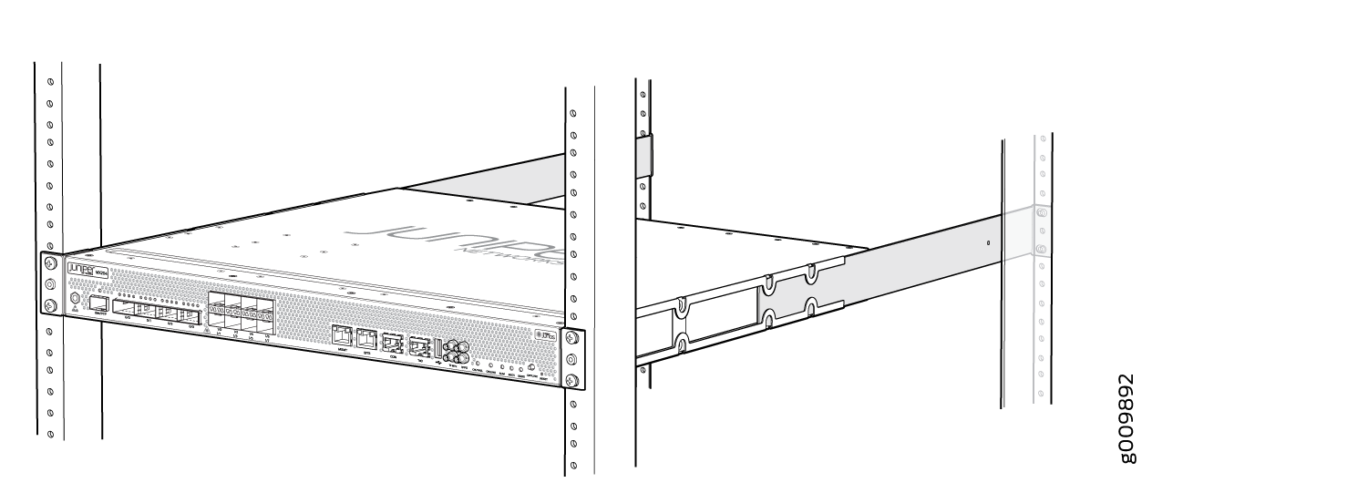
Carefully slide the router onto the mounting brackets until the front-mounting brackets attached to the chassis contact the rack rails as shown:
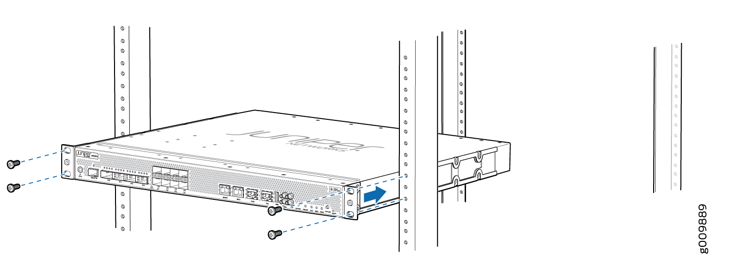
Install mounting screws into each of the open front-mounting holes aligned with the rack, starting from the bottom, and secure them tightly as shown:
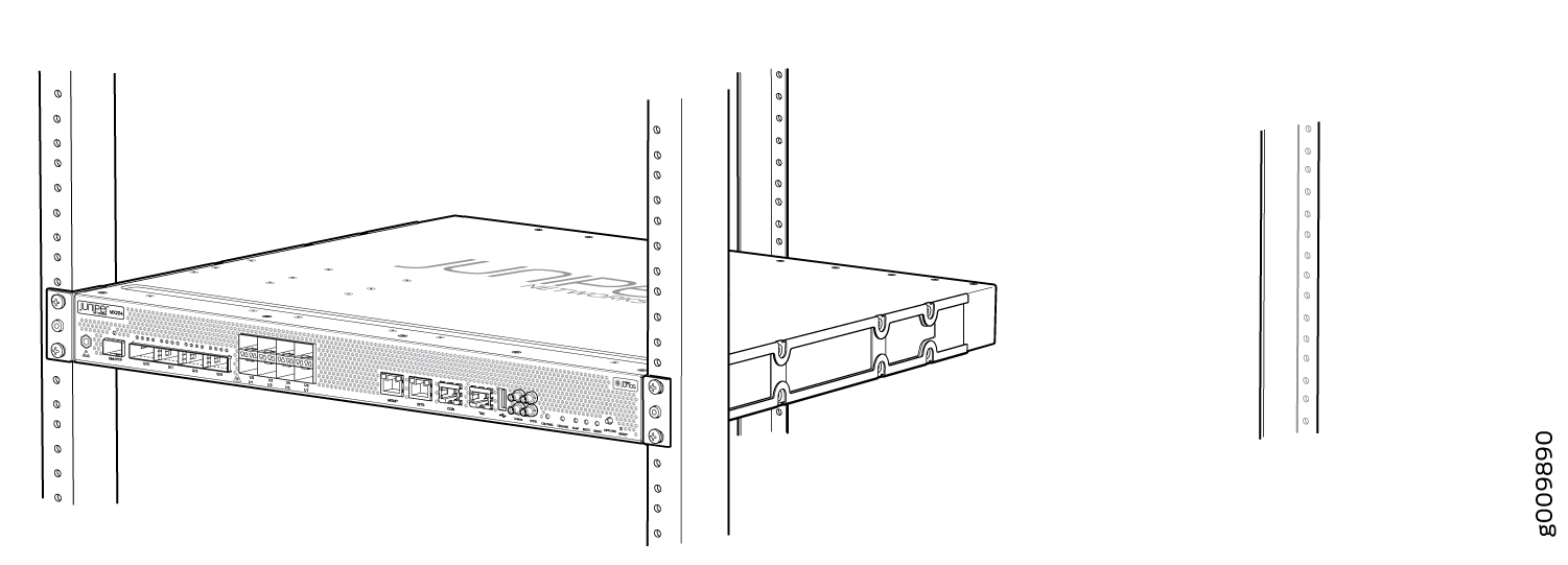
On the rear of the chassis, slide the rear-mounting brackets on either side of the chassis until the rear-mounting brackets contact the rack rails as shown.
The rear-mounting brackets on each side of the chassis are movable. You can adjust the brackets according to the depth of the rack.
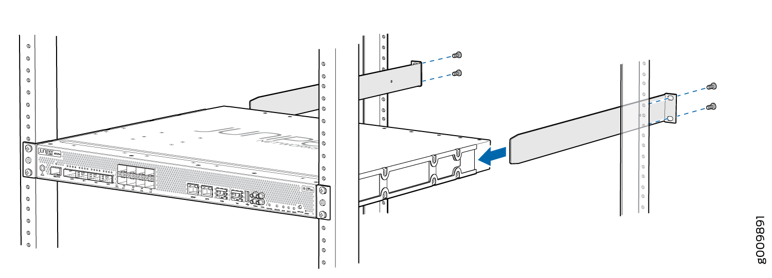
Install mounting screws into each of the open rear-mounting holes aligned with the rack, starting from the bottom, and secure them tightly.
Visually inspect the alignment of the chassis. If the chassis is installed properly in the rack, all the mounting screws on one side of the rack are aligned with the mounting screws on the opposite side and the router is level. A fully secured and installed router in a four-post rack is shown:
Connect to Power
Ground the MX204 Router
To meet safety and electromagnetic interference (EMI) requirements and to ensure proper operation, the router must be adequately grounded before power is connected.
A protective earthing terminal bracket is required for connecting the chassis to earth ground. This two-holed bracket attaches on the side of the chassis through the mounting rail and provides a protective earthing terminal for the router. The grounding points are in the form of studs sized for M5 Pan Head screws. The M5 Pan Head screws with integrated washers are provided in the accessory kit. The grounding points are spaced at 0.75-in. (19.1-mm) centers.
You ground the router by connecting a grounding cable to earth ground and then attaching it to the chassis grounding points by using two M5 Pan Head screws. You must provide the grounding cables (the cable lugs are supplied with the router).
The grounding lug required is a Panduit LCD10-10A-L or equivalent (not provided). The grounding lug accommodates 14–10 AWG (2–5.3 mm²) stranded wire. The grounding cable that you provide for the chassis must be the same size or heavier than the input wire of each power supply. Minimum recommendations are 14–10 AWG (2–5.3 mm²) stranded wire, 60° C wire, or as permitted by local code.
Before you ground the router:
Verify that a licensed electrician has attached the cable lug provided with the router to the grounding cable.
Ensure that all grounding surfaces are clean and brought to a bright finish before grounding connections are made.
To ground the MX204 router, do the following:
Attach an electrostatic discharge (ESD) grounding strap to your bare wrist, and connect the other end of the strap to an approved site ESD grounding point. See the instructions for your site.
Ensure that all grounding surfaces are clean and brought to a bright finish before grounding connections are made.
Connect the grounding cable to a proper earth ground.
Detach the ESD grounding strap from the site ESD grounding point.
Connect the grounding strap to one of the ESD points on the chassis.
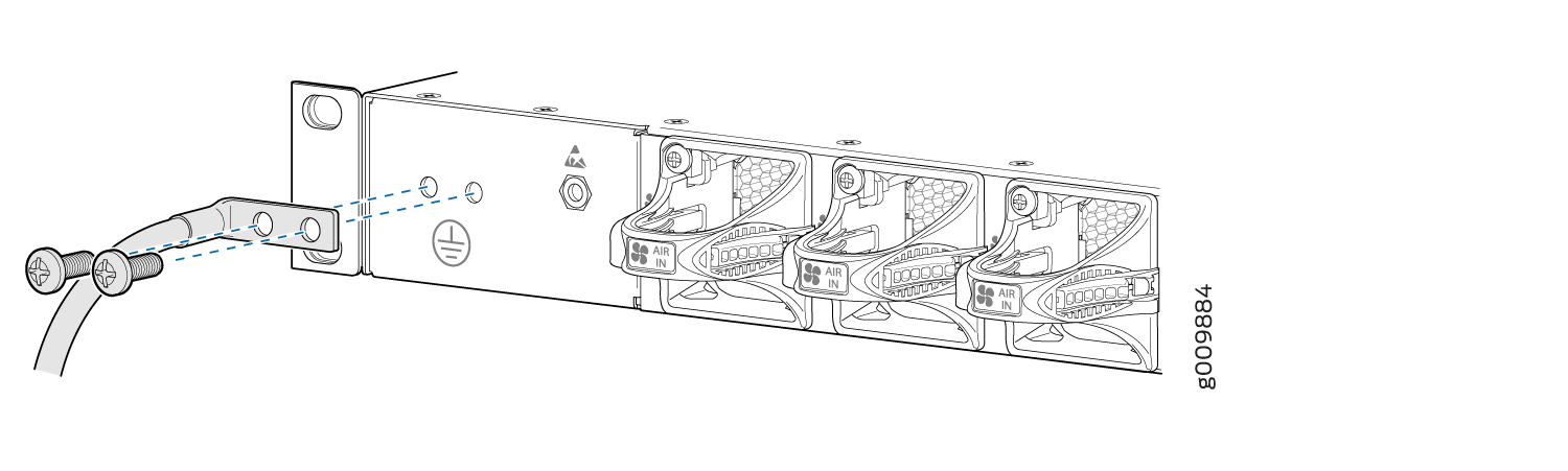
Place the grounding cable lug over the grounding point on the side of the chassis.
 1—
1—Grounding point
Secure the grounding cable lug with the screws. The holes are sized to accommodate M5 Pan Head screws.
Dress the grounding cable and verify that it does not touch or block access to router components, and that it does not drape where people could trip on it.
Connect the Power Cord and Power On the Router
The AC-powered MX204 router comes with two AC power supplies preinstalled on the rear of the chassis. The power supplies are hot-insertable and are field-replaceable units (FRUs).
You must ground the router before connecting the AC power cord.
Do not mix AC and DC power supplies in the same chassis.
Each power supply must be connected to a dedicated AC power feed and a dedicated customer-site circuit breaker. We recommend that you use a dedicated customer-site circuit breaker rated for either 20 A (110 VAC) minimum or 16 A (220 VAC) minimum, or as required by local code.
|
Item |
Specification |
|---|---|
|
AC input voltage |
Operating range: 90-264 VAC |
To connect the power cord and power on the router, do the following:
Locate power cords that have a plug appropriate for your geographical location.
Attach an ESD grounding strap to your bare wrist and connect the strap to one of the ESD points on the chassis.
Connect the power cord to the power supply.
Insert the power cord plug into an external AC power source receptacle.
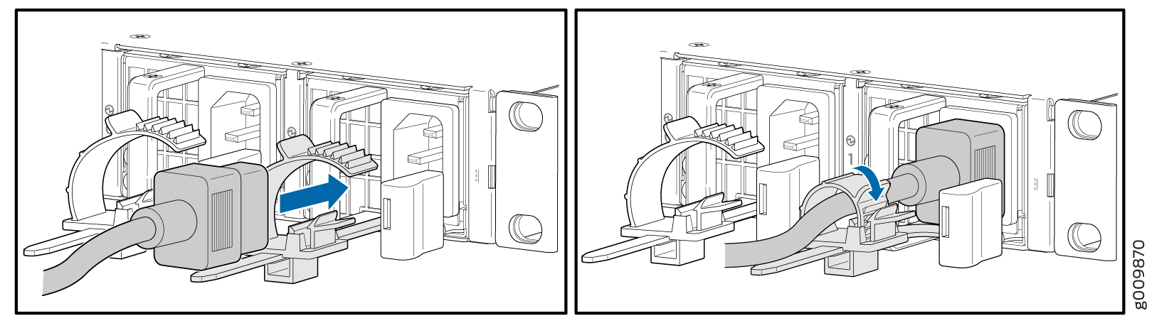
Push the end of the AC power cord retainer strip into the hole next to the inlet on the power supply faceplate until it snaps into place. Ensure that the loop in the retainer strip faces toward the power cord.
Press the small tab on the retainer strip to loosen the loop. Slide the loop until you have enough space to insert the power cord coupler into the inlet.
Insert the power cord coupler firmly into the inlet.
Slide the loop toward the power supply until it is snug against the base of the coupler.
Press the tab on the loop and draw out the loop into a tight circle.
Dress the power cord appropriately. Verify that the power cord does not block the air exhaust and access to router components, or drape where people could trip on it.
Repeat Step 1 through Step 10 for the remaining power supply.
Power on the power supply at source. Observe the power status LED on the router. If an AC power supply is installed correctly and functioning normally, the status LED lights green steadily.
If the status LED indicates that the power supply is not functioning normally, repeat the installation and cabling procedures.