Connect the MX304 to Power
Tools and Parts Required for MX304 Router Grounding and Power Connections
To ground and to provide power to the router, you need the following tools and parts:
Phillips (+) screwdrivers, numbers 1 and 2
Socket nutdriver
2.5-mm flat-blade (–) screwdriver
Torque-controlled driver, with a maximum torque capacity of 23 lbf-in. (2.6 Nm) to 25 lbf-in. (2.8 Nm) for tightening screws to terminals on each power supply on a DC-powered router.
CAUTION:The maximum torque rating of the terminal screws on the DC power supply is 23 lbf-in. (2.6 Nm) to 25 lbf-in. (2.8 Nm). If you apply excessive torque, the terminal screws might be damaged. Use only a torque-controlled driver to tighten screws on the DC power supply terminals. Use an appropriately sized driver, with a maximum torque capacity of 6 lb-in. or less. Ensure that the driver is undamaged and properly calibrated and that you have been trained in its use. You might want to use a driver that is designed to prevent overtorque when the preset torque level is achieved.
Wire cutters
Electrostatic discharge (ESD) grounding wrist strap
Ground the MX304 Router
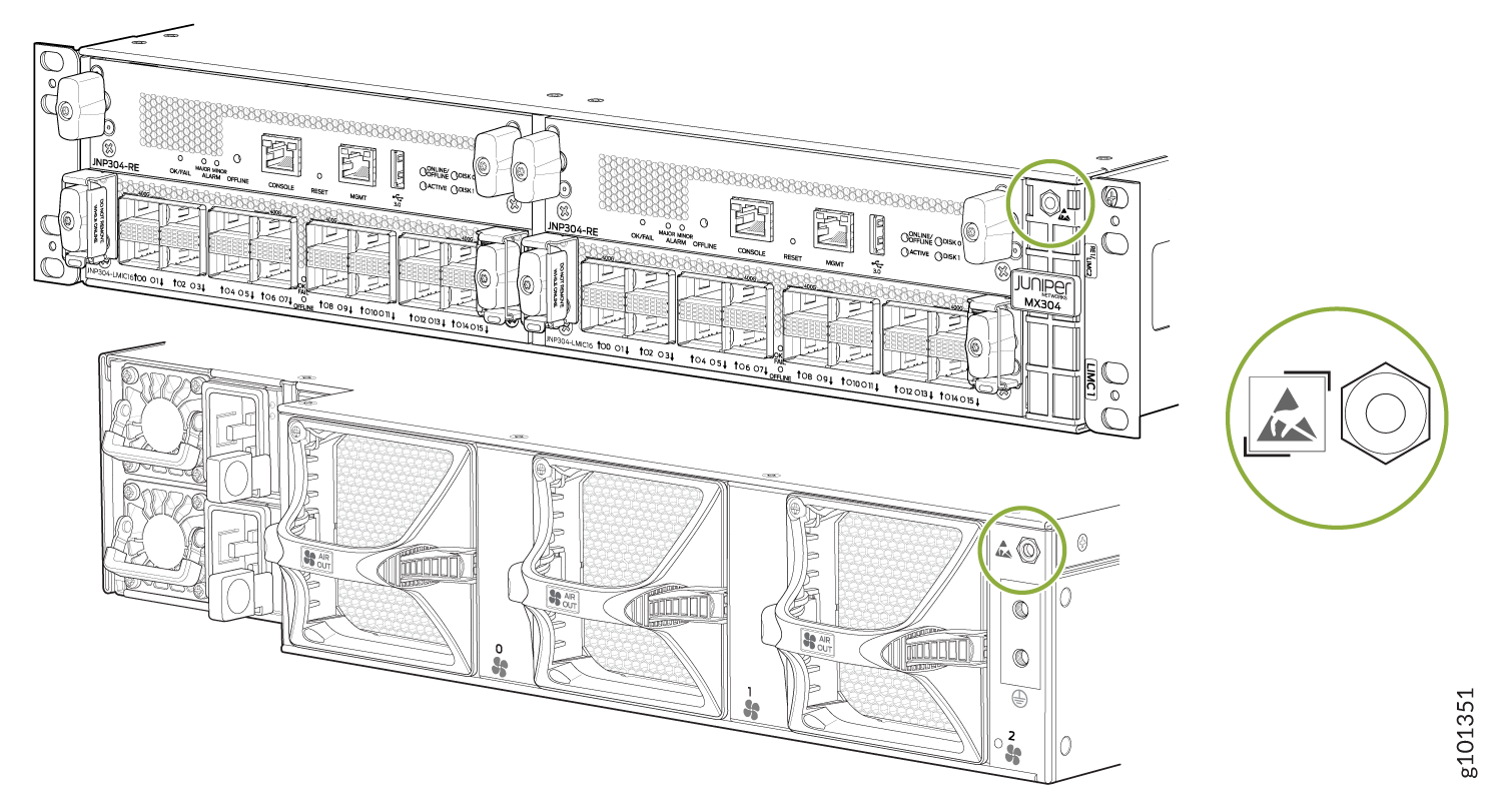
You must install the MX304 in a restricted-access location and ensure that the chassis is always properly grounded. The MX304 has a two-hole protective grounding terminal on the chassis. See Figure 2. We recommend that you use this protective grounding terminal for grounding the chassis regardless of the power supply configuration. However, if additional grounding methods are available, you can also use those methods. For example, you can use the grounding wire in the AC power cord or use the grounding terminal or lug on a DC power supply. This tested system meets or exceeds all applicable EMC regulatory requirements with the two-hole protective grounding terminal.
To ground the router, connect a grounding cable to earth ground and then attach it to the chassis grounding points with two M6 pan head screws. Figure 2 shows the grounding point location on the chassis. You'll need to provide the grounding cables and the cable lugs. For grounding cable specifications, see MX304 Router Grounding Specifications.
To ground the router:
- Verify that a licensed electrician has attached the cable lug provided with the router to the grounding cable.
- Attach an electrostatic discharge (ESD) grounding strap to your bare wrist, and connect the strap to an approved site ESD grounding point. See the instructions for your site.
- Ensure that all grounding surfaces are clean and brought to a bright finish before grounding connections are made.
- Connect the grounding cable to a proper earth ground.
- Detach the ESD grounding strap from the site ESD grounding point.
- Attach an ESD grounding strap to your bare wrist and connect the strap to one of the ESD points on the chassis.
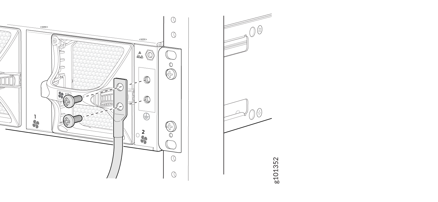
- Place the grounding cable lug over the grounding points on the chassis.
- Secure the grounding cable lug with the screws. The holes are sized for M6 pan head screws (see Figure 2).
- Dress the grounding cable, and verify that it doesn't touch or block access to router components, and that it doesn't drape where people could trip on it.
See Also
Connect Power to an AC-Powered MX304 Router
Do not mix AC, DC, or HVAC/DC power supplies within the same router. This might damage the router.
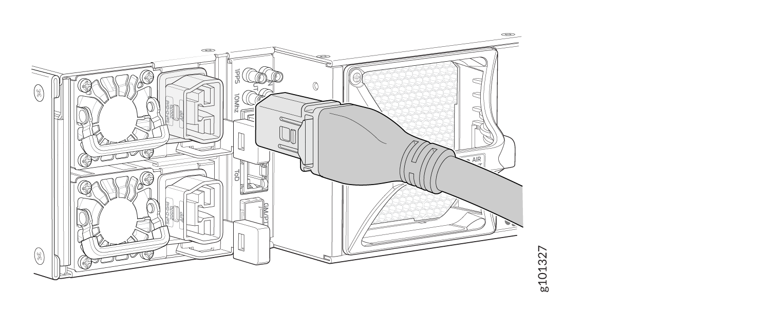
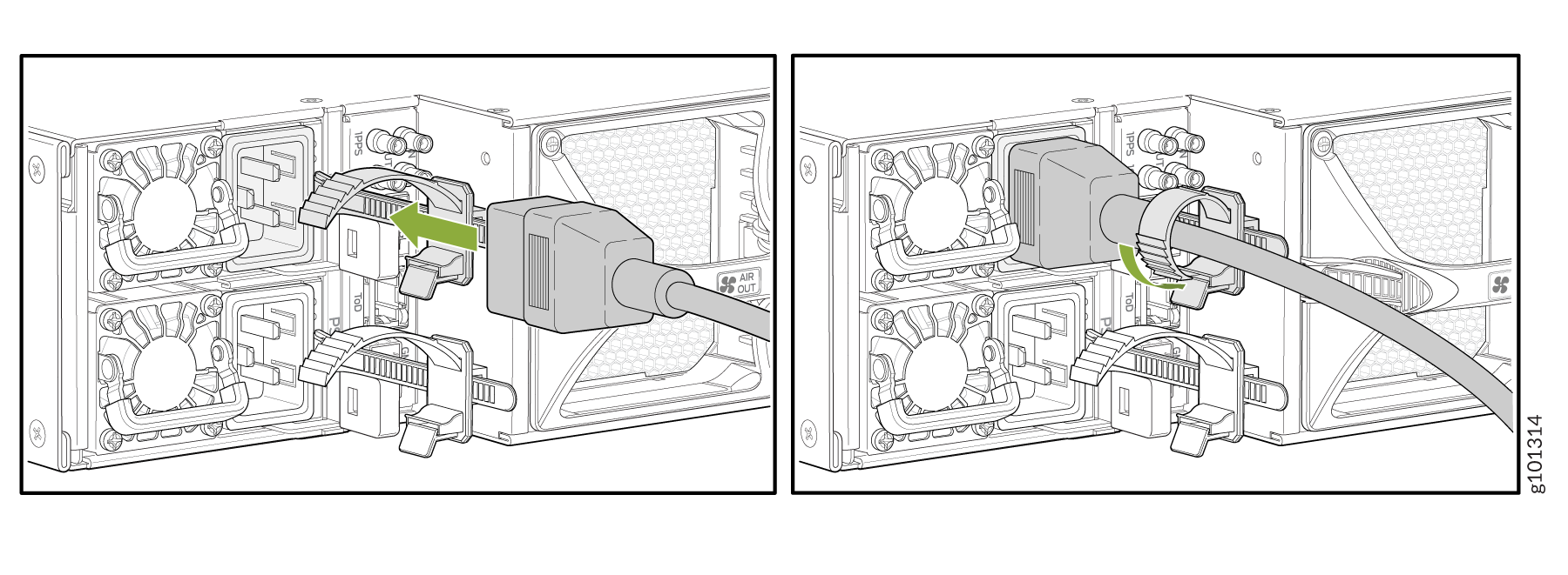
To connect AC power to the router, attach power cords from the AC power sources to the AC appliance sockets on the power supplies. Here's how:
See Also
Connect Power to a DC-Powered MX304 Router
Do not mix AC, DC, or HVAC/DC power supplies within the same router. Damage to the router might occur.
Before you perform DC power procedures, ensure there is no power to the DC circuit. To ensure that all power is off, locate the circuit breaker on the panel board that services the DC circuit, switch the circuit breaker to the off position, and tape the switch handle of the circuit breaker in the off position.
You connect DC power to the router by attaching power cables from the external DC power sources to the terminal block on the power supply faceplate. You must provide the power cables (the cable lugs are supplied with the router). For power cable specifications, see DC Power Cable Specifications for the MX304 Router.
To connect the DC source power cables to the router for each power supply:
-
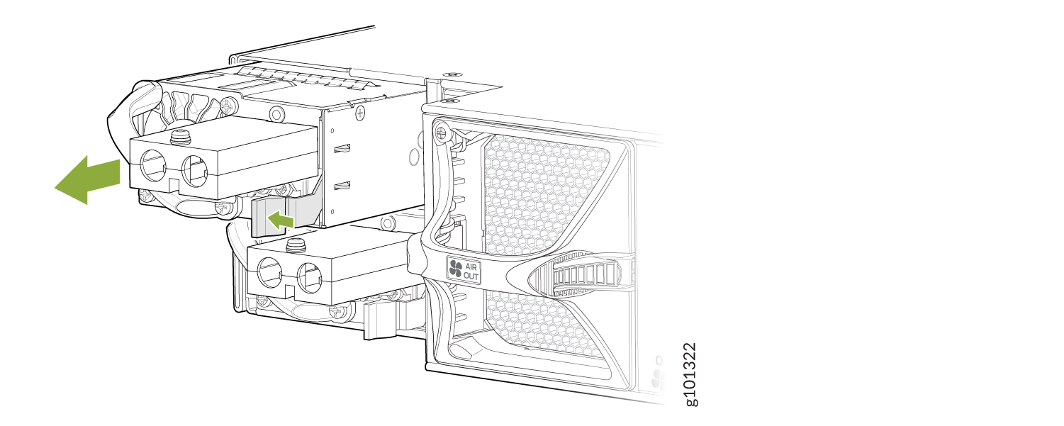
Remove the DC power supplies from the chassis. See Figure 4.
Figure 4: Removing the DC Power Supply from the Chassis
-
Using a screwdriver (anticlockwise) unscrew the nut on top of the terminal block. See
Figure 7
Figure 5: Removing the Terminal Block Cover

-
Install heat-shrink tubing insulation around the power
cables.
To install heat-shrink tubing:
-
Slide the tubing over the portion of the cable where it is attached to the lug barrel. Ensure that tubing covers the end of the wire and the barrel of the lug attached to it.
-
Shrink the tubing with a heat gun. Ensure that you heat all sides of the tubing evenly so that it shrinks around the cable tightly.
Figure 6 shows the steps to install heat-shrink tubing.
Note:Do not overheat the tubing.
Figure 6: How to Install Heat-Shrink Tubing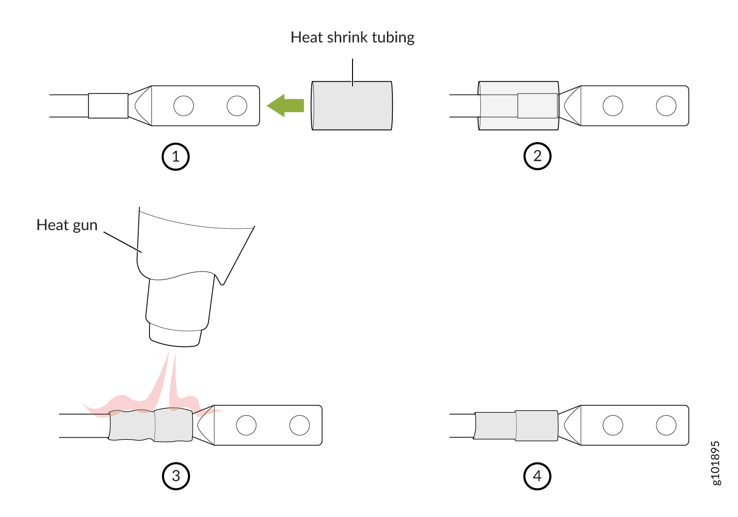
-
-
Remove the nuts from the four terminals. See Figure 7.
Figure 7: Removing the Nuts from the Terminals

-
Secure each power cable lug to the terminal with the nuts. Tighten the nuts on the
power supply terminals until snug by using the screwdriver. Apply between 23 lbf-in. (2.6
Nm) to 25 lbf-in. (2.8 Nm) of torque to the nuts. Do not apply vertical force while
tightening the screws. Do not overtighten the nuts. (Use a socket nutdriver.) See Figure 8.
Figure 8: Connecting the DC Cable

-
Secure the positive (+) DC source power cable lug to the RTN (return) terminal.
-
Secure the negative (–) DC source power cable lug to the –48V/-60V (input) terminal.
CAUTION:Ensure that each power cable lug seats flush against the surface of the terminal block as you are tightening the nuts. Ensure that each nut is properly threaded into the terminal. Applying installation torque to the nuts when improperly threaded can result in damage to the terminal.
CAUTION:You must ensure that power connections maintain the proper polarity. The power source cables might be labeled (+) and (–) to indicate their polarity. There is no standard color coding for DC power cables. The color coding used by the external DC power source at your site determines the color coding for the leads on the power cables that attach to the terminal studs on each power supply.
Note:For a list of supported DC power cables, see DC Power Cable Specifications for the MX304 Router the section.
-
-
Install the power supply in the chassis.
Figure 9: Installing the Power Supply in the Chassis

See Also
Connect Power to an HVAC/DC Powered MX304 Router
Do not mix AC, DC, or HVAC/DC power supplies within the same router. Damage to the router might occur.
You connect high-voltage AC/DC power to the router by attaching power cords from the AC/DC power sources to the HVAC/DC appliance inlets located on the power supplies.
To connect the HVAC/DC power cords to the router for each power supply: