MX304 Routing Engine
MX304 Routing Engine Description
The MX304 host subsystem consists of up to two Routing Engines. The host subsystem provides routing protocol processes, as well as software processes that control the router’s interface, the chassis components, system management, and user access to the router. A redundant system would host two Routing Engine cards, one being the primary and the other, the backup. The MX304 Routing Engine is a hot-swappable FRU and has front panel interfaces. You can install one or two Routing Engines on the router. The Routing Engine processor runs routing protocols and software daemons for chassis and FRU management.
Install two Routing Engines for redundant protection. If you install only one Routing Engines, you can install it in slot 0 or slot 1. By default, slot 0 functions as the primary.
If one of the Routing Engine fails, do not remove the failed Routing Engine until you have a replacement or blank panel to install.
The MX304 router supports JNP304-RE.
This topic covers:
Routing Engine Functions
Each Routing Engine supports:
- Intel Icelake Based Multicore Processor CPU.
- Four DDR-4 DIMM slots, on two double data rate (DDR) channels with ECC support.
-
Default configuration of 4x32-GB DDR4 RAM for a maximum capacity of 128 GB.
- Two SSDs (2x200GB). Provides storage for redundant software images, configuration files, log files etc. Supports M.2 SATA SSDs
- One USB port on the front panel supporting USB 3.0.
- One 10/100/1000 BASE-T RJ45 management port.
- One RJ45 serial console port.
- Trusted platform module (TPM) 2.0 cryptographically downloads the image and avoids hardware tampering.
- Secure boot.
- Real time clock with battery backup and facility to monitor battery.
Routing Engine Front Panel
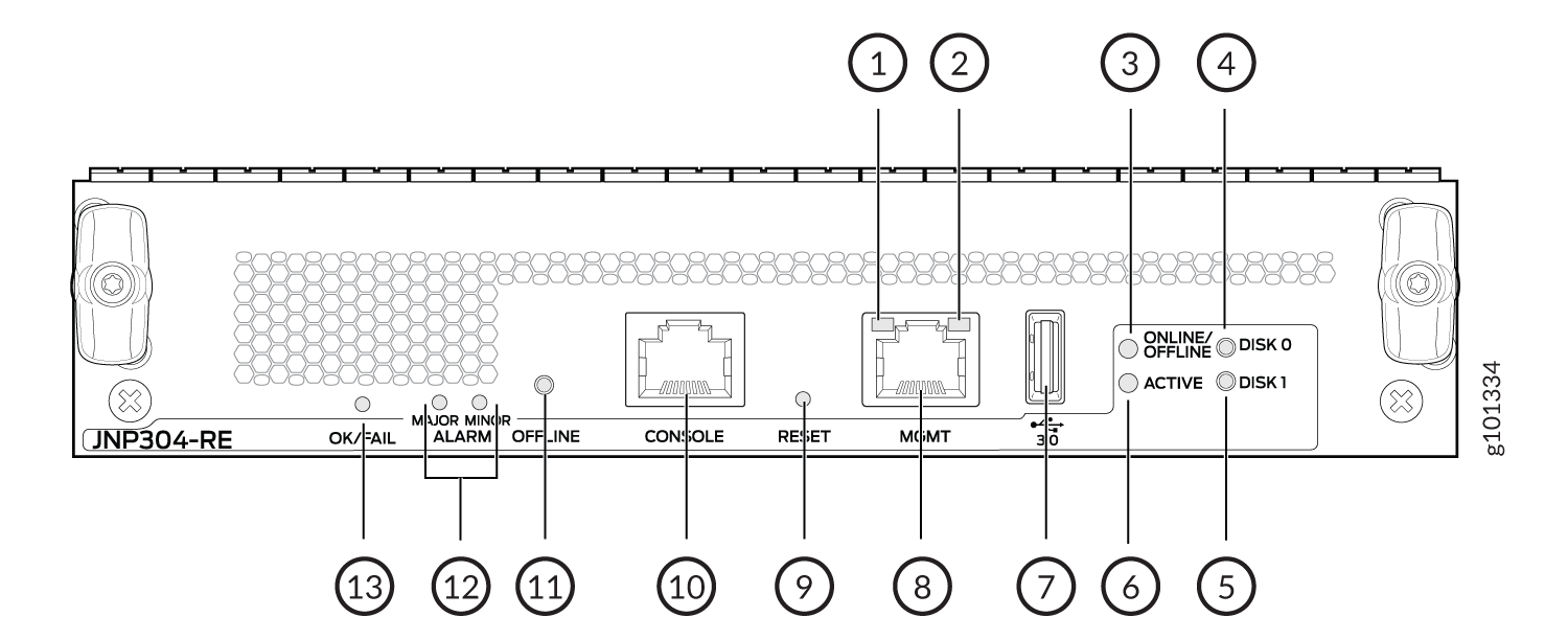
Figure 1 shows the front panel of the MX304 Routing Engine (model number: JNP304-RE).

1 — Management (MGMT) port link activity LED | 8 — Management (MGMT) port |
2 — Management (MGMT) port status LED | 9 — Reset button |
3 — Offline and Online LED | 10 — Console port |
4 — Disk 0 LED | 11 — Offline button |
5 — Disk 1 LED | 12 — Major and Minor Alarm LED |
6 — Active LED | 13 — OK/Fail LED |
7 — USB port |
The MX304 router with JNP304-RE-LT-R supports only Junos Limited image. The Junos Limited image does not have data-plane encryption and is intended only for countries in the Eurasian Customs Union because these countries have import restrictions on software containing data-plane encryption. Unlike the Junos worldwide image, the Junos Limited image supports control plane encryption through Secure Shell (SSH) and Secure Sockets Layer (SSL), thus allowing secure management of the system. The Limited Restriction Routing Engines boots only the encryption free Junos software and fails to boot if the fully encrypted Junos software is used for booting. The Junos upgrade and VMHost upgrade using non-limited version of Junos software fails on the JNP304-RE-LT-R.
The command show chassis hardware [models | clei-models |
extensive] displays the model number and helps
identifying the different SKUs.
Routing Engine Interface Ports
The ports located on the Routing Engine connect the Routing Engine to one or more external devices on which system administrators can issue Junos OS CLI commands to manage the router.
The Routing Engine interface ports with the indicated labels function are as follows (see Figure 1):
-
CONSOLE—Connects the Routing Engine to a system console through a serial cable with an RJ-45 connector.
-
MGMT—Connects the Routing Engine through an Ethernet connection to a management LAN (or any other device that plugs into an Ethernet connection) for out-of-band management. The port uses an autosensing RJ-45 connector to support 10 Mbps, 100 Mbps, or 1000 Mbps connections. Two small LEDs (a link activity LED and a status LED) on the port indicate the connection in use.
-
USB—Provides a removable media interface through which you can install Junos OS manually. Junos OS supports USB version 1.0 and later.
MX304 Routing Engine LEDs
The Routing Engine is an integrated board and a single FRU that provides Routing Engine functionality.
The LEDs—labeled OK/FAIL, MAJOR/MINOR ALARM, MGMT, OFFLINE/ONLINE, ACTIVE, DISK 0/DISK 1—are located directly on the faceplate of the Routing Engine. Table 1 describes the functions of the Routing Engine interface.
The functioning of the MX304 router is controlled by the Routing Engine, and the LEDs present on the Routing Engine displays the status and functioning of the MX304 chassis.
|
Label |
Color |
State |
Description |
|---|---|---|---|
|
OK/FAIL |
Red |
On steadily |
Routing Engine fault condition. |
| Green |
On steadily |
Operating okay. | |
|
Off |
Offline. |
||
| MAJOR ALARM |
Red |
On steadily | Major alarm is active. |
| Off | No alarm. | ||
| MINOR ALARM |
Amber |
On steadily | Minor alarm is active. |
| Off | No alarm. | ||
| MGMT (Status LED) |
Off |
Off | Link down. |
|
Yellow |
On steadily |
Link up in 10 Mbps/100 Mbps. | |
|
Green |
On steadily |
Link up in 1000 Mbps. |
|
| MGMT (Link Activity LED) |
Green |
Blinking |
Link up, activity. |
|
ONLINE/OFFLINE |
Green |
On |
Routing Engine is on and working okay. |
|
Off |
Off |
Offline |
|
|
Green |
Blinking |
Routing Engine is starting Junos OS. |
|
|
ACTIVE |
Green |
On |
Routing Engine is active (primary). |
|
Off |
Routing Engine is redundant. | ||
|
DISK 0 |
Green |
Blinking |
Activity is present. |
|
Off |
No activity. |
||
|
DISK 1 |
Green |
Blinking |
Activity is present. |
|
Off |
No activity. |
