Fast Track to Rack Installation and Power
This procedure guides you through the simplest steps for the most common installation to mount your router in a rack and connect it to power.
Mount the PTX10002-36QDD on a Square Hole Four-Post Rack
You can mount the router on a four-post rack or cabinet by using the rack mount kit shipped with the router by default. We’ll walk you through the steps to mount a router and connect it to power.
The router chassis weighs approximately 63.6 lb (28.85 kg) with three fan modules and two power supply units (PSUs) installed.
You must install the router in a restricted-access location and ensure that the chassis is always grounded properly.
Before you mount, review the following:
Mount the Router
Place the router on a flat, stable surface.
Wrap and fasten one end of the ESD grounding strap around your bare wrist, and connect the other end to a site ESD point.
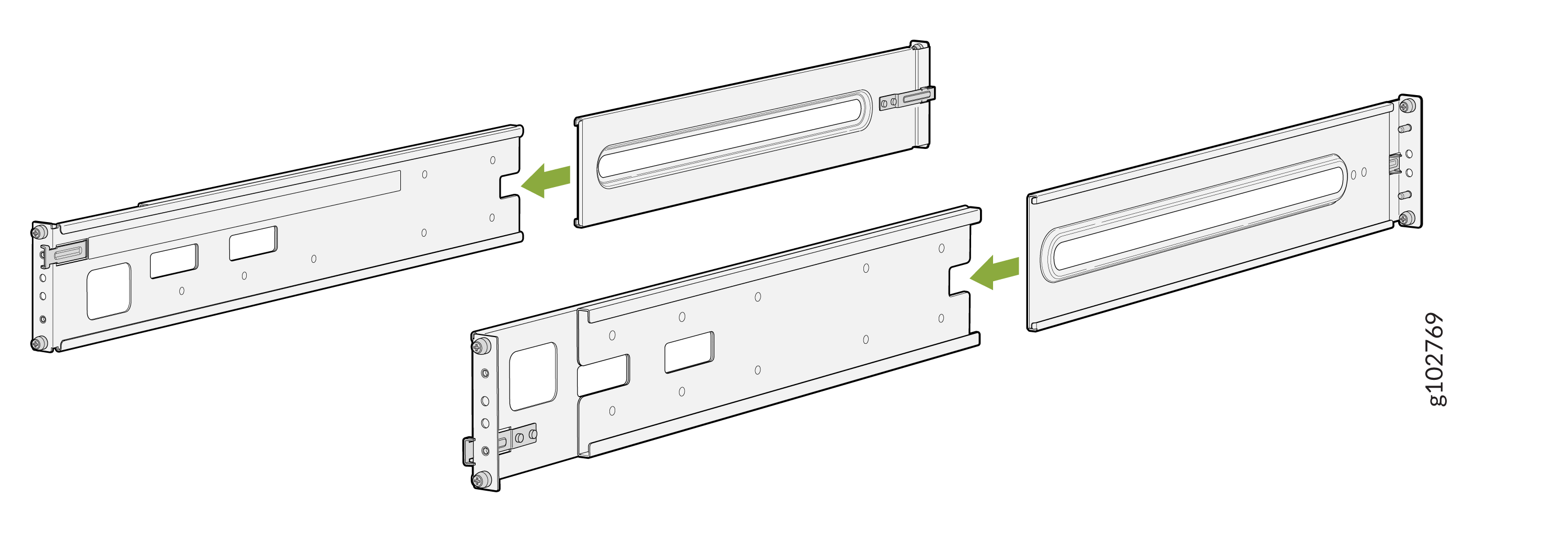
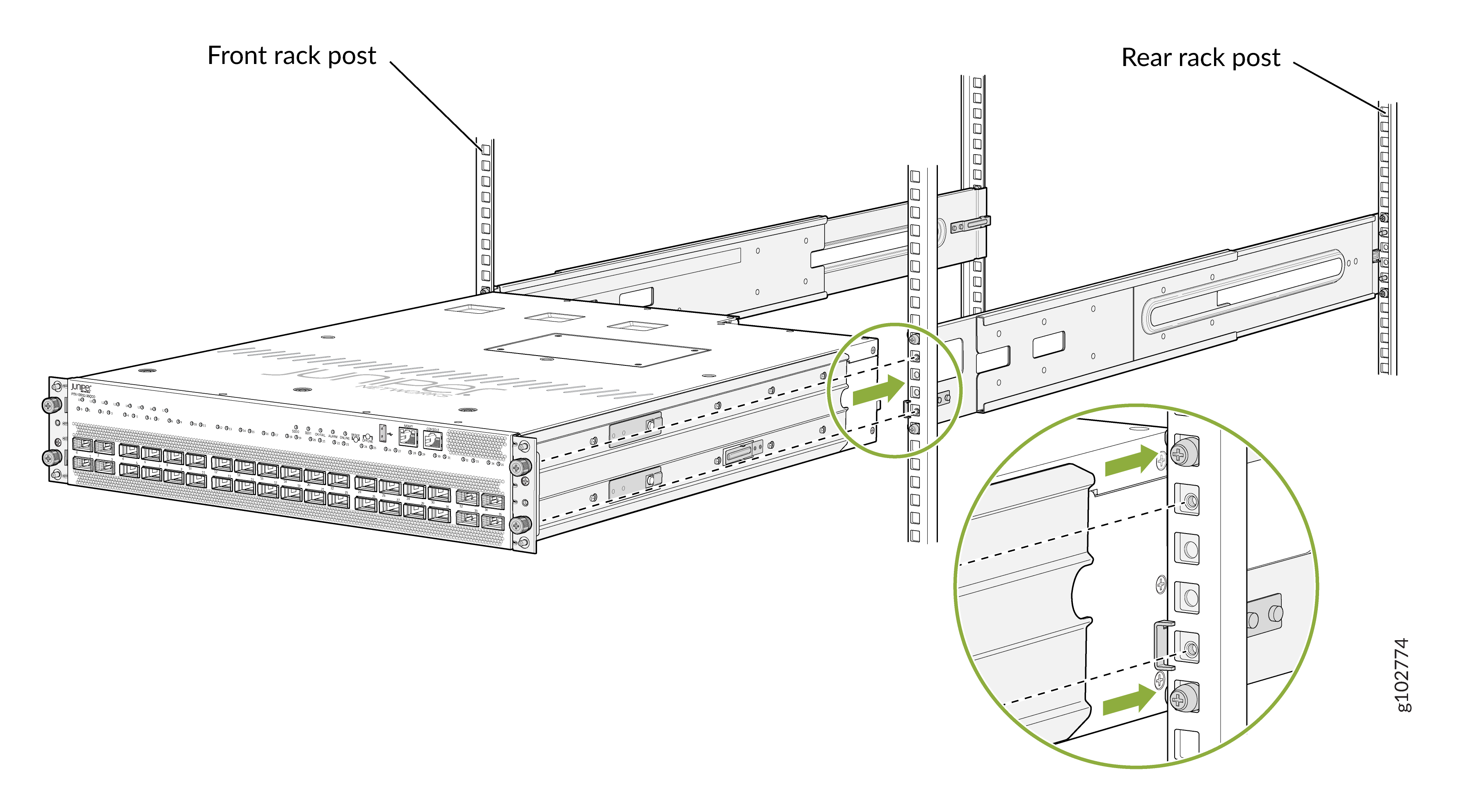
Assemble both the right and left mounting rails. Align the rear mounting rails with the guides on the front mounting rails and gently slide the rear mounting rails into the front mounting rails.
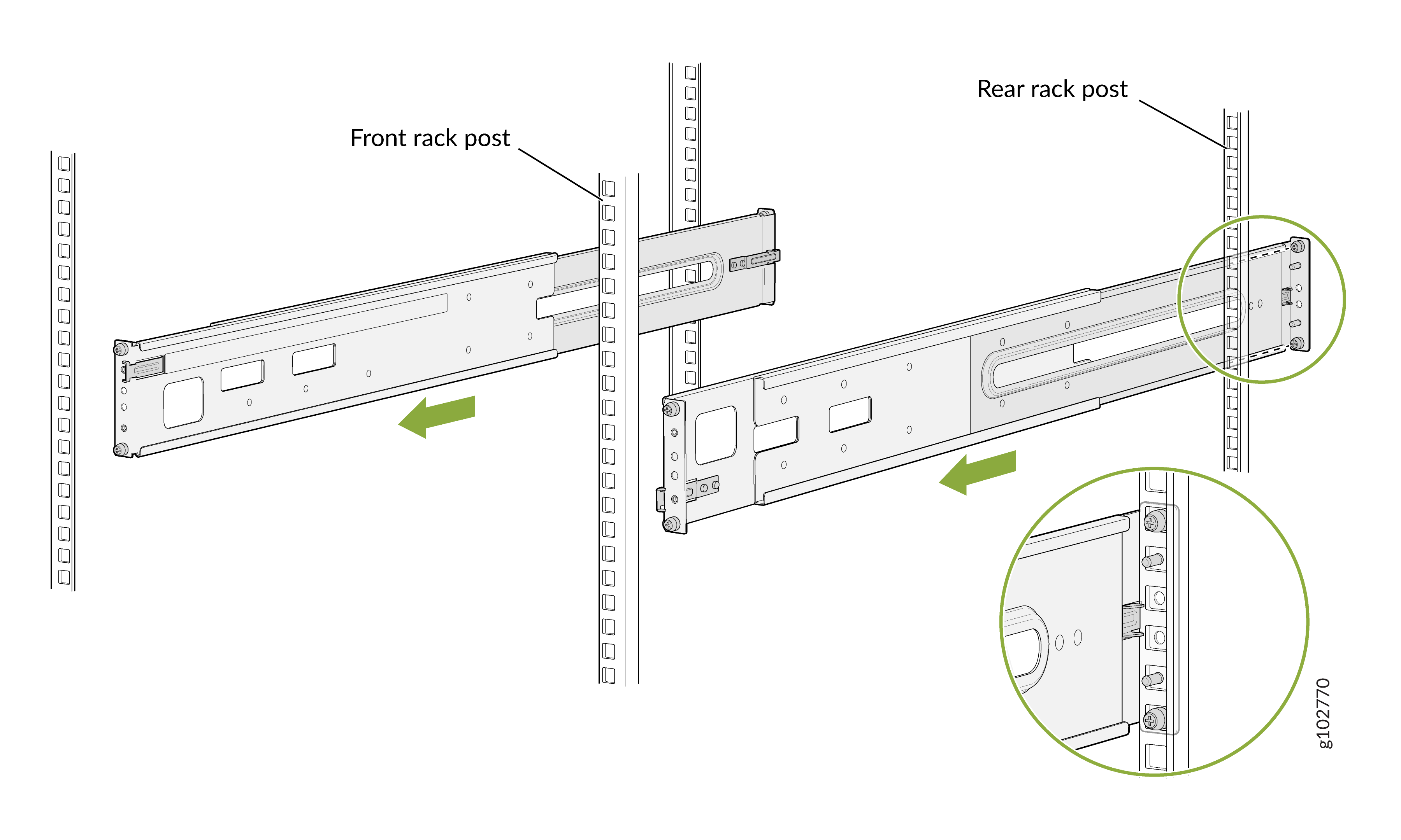
Attach the rear mounting rails to the rack posts—tighten the captive thumb screws by using a number 2 Phillips (+) screwdriver.
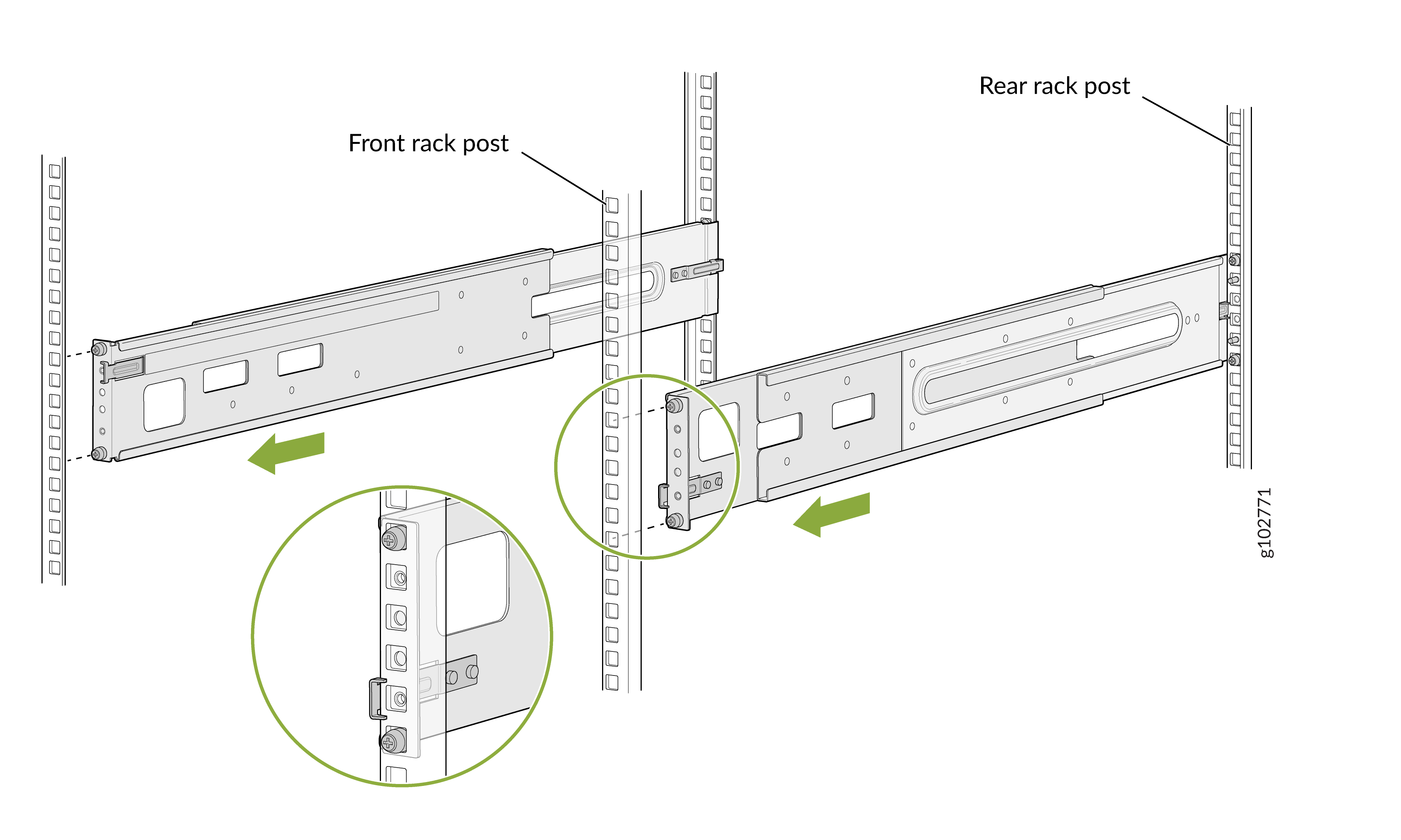
Attach the front mounting rails to the rack posts—tighten the captive thumb screws by using a number 2 Phillips (+) screwdriver.
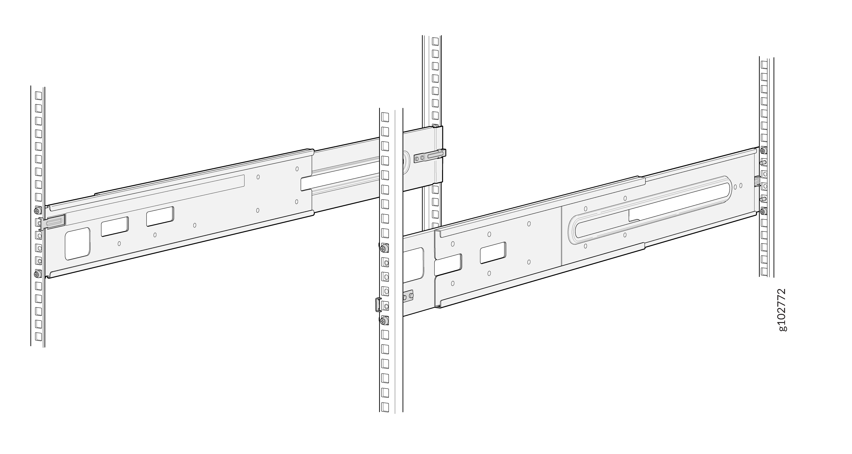
Ensure that the mounting rails are level by verifying that all screws on one side of the rack align with the screws on the other side.
Attach the mounting brackets to the router chassis.
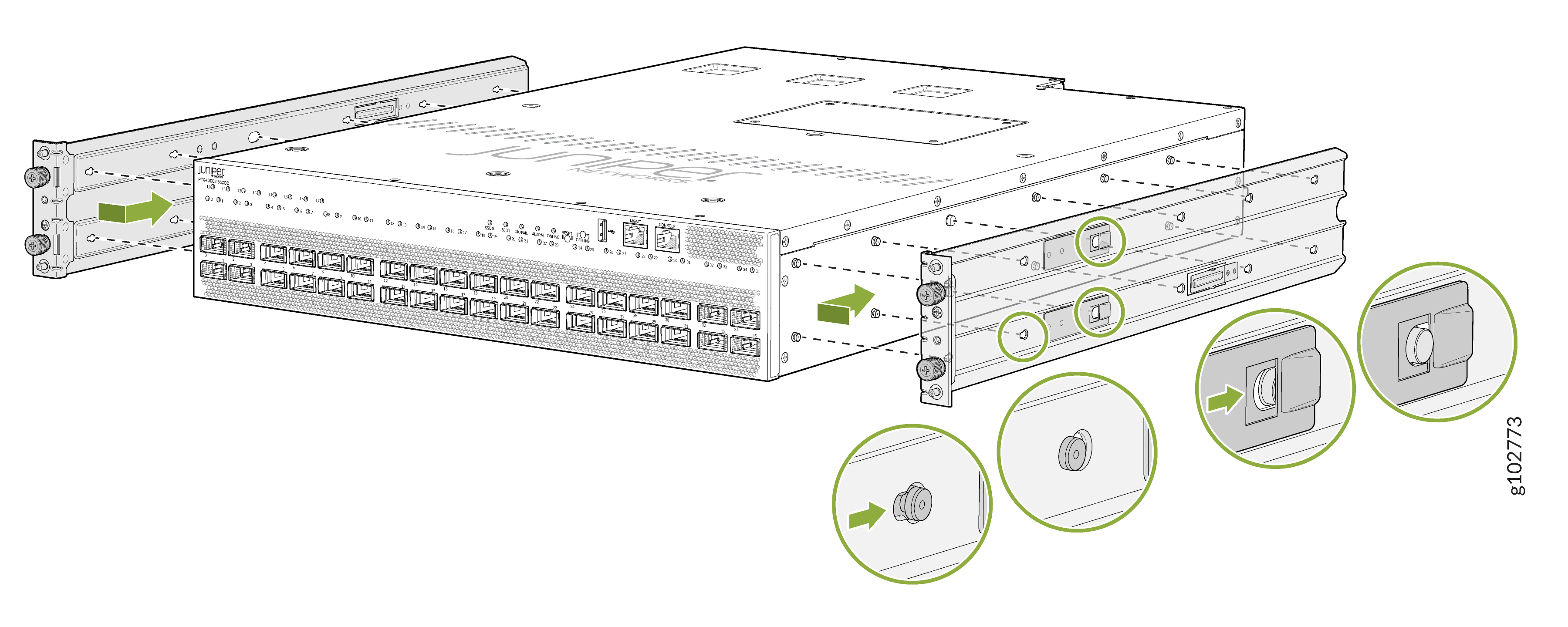
Align the mounting brackets with the guides on the mounting rails and gently slide the chassis on to the mounting rails until the chassis locks in place.
Secure the router to the rack—tighten the thumb screws by using the screwdriver.
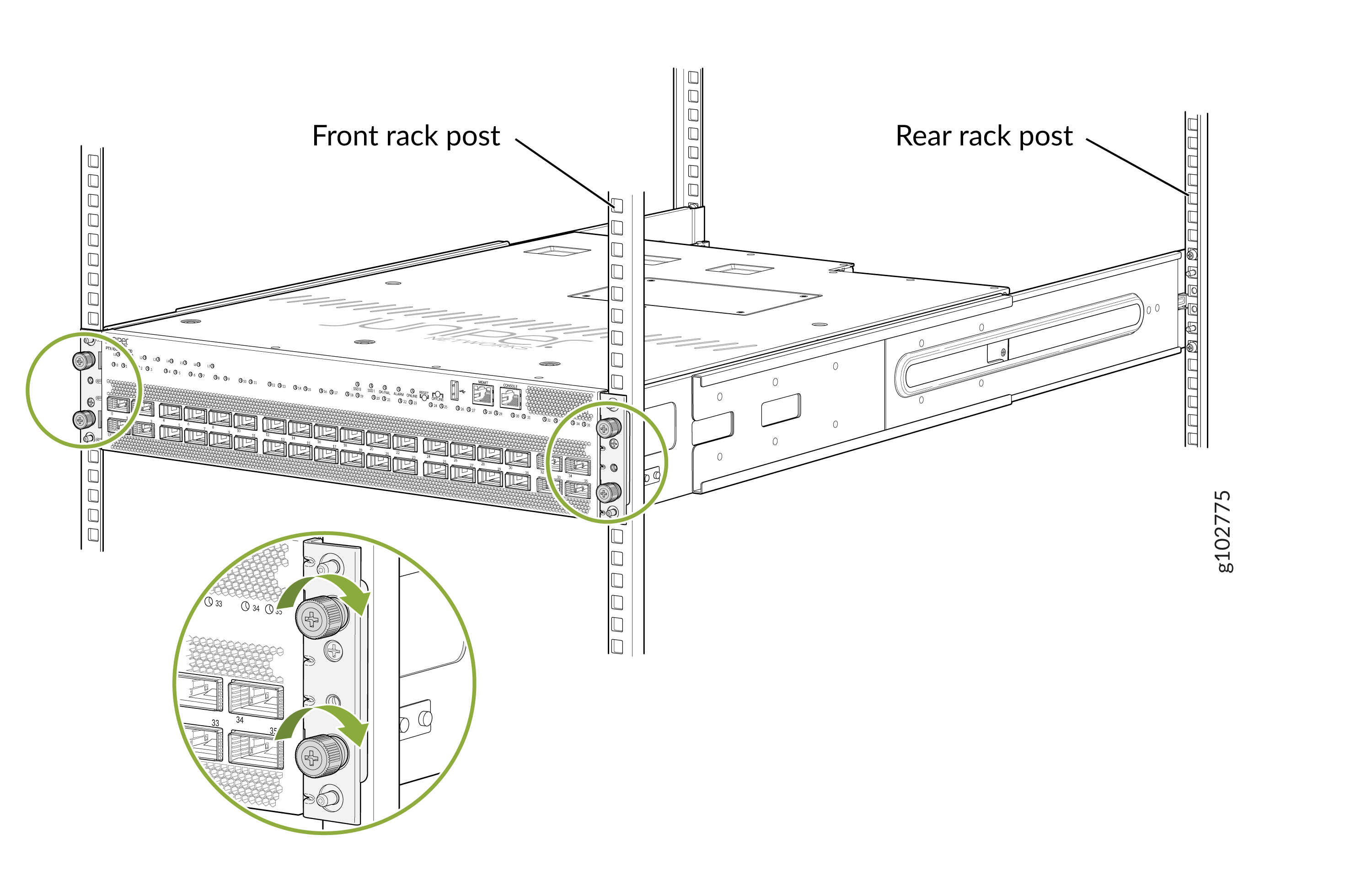
Ensure that the router chassis is level by verifying that all the screws on one side of the rack align with the screws on the other side.
Connect to Power
To connect the router to AC/HVAC/HVDC power:
Install the Power Supply Units
We ship the router with the PSUs preinstalled in the rear panel. If the PSUs are not installed in the chassis, follow the steps in this procedure to install the PSUs. The PSUs are hot-removable and hot-insertable field-replaceable units (FRUs): You can remove and replace them without powering off the router or disrupting router functions.
If the PSU has protective plastic wrap, peel and remove the plastic wrap from all sides of the PSU.
Wrap and fasten one end of the ESD wrist strap around your bare wrist, and connect the other end of the strap to a site ESD point.
Taking care not to touch PSU components, pins, leads, or solder connections, remove the PSU from its bag.
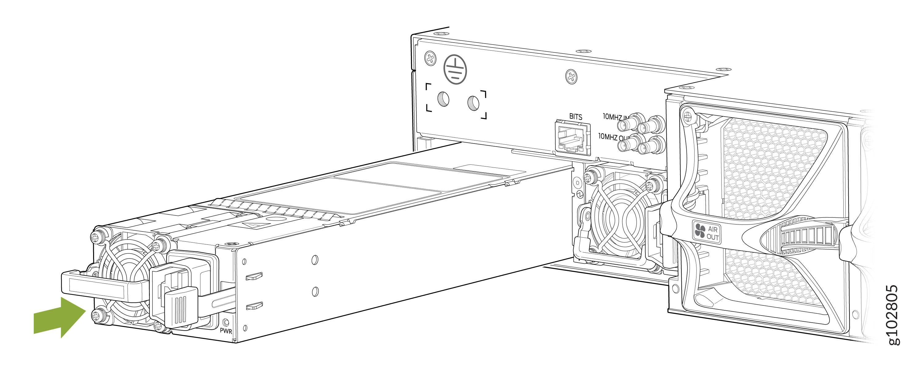
Using both hands, place the PSU in the PSU slot on the rear panel and slide it in until it is fully seated and the locking lever slides into place.
 Note:
Note:If you have a Juniper Care service contract, register any addition, change, or upgrade of hardware components at https://www.juniper.net/customers/support/tools/updateinstallbase/ . Failure to do so can result in significant delays if you need replacement parts. This note does not apply if you replace existing components with the same type of component.
Ground the Router
To meet safety and EMI requirements and to ensure proper operation, you must connect the chassis to earth ground before you connect it to power. You must use the protective earthing terminal on the router chassis to connect it to earth ground. For installations that require a separate grounding conductor to the chassis, use the protective earthing terminal on the router chassis to connect to the earth ground.
An AC/HVAC/HVDC-powered PTX10002-36QDD gains additional grounding when you plug the power supply unit (PSU) in the device into a grounded power outlet by using a power cord appropriate for your geographical location. See Table 3.
You must install the router in a restricted-access location and ensure that the chassis is always properly grounded. The router has a two-hole protective grounding terminal on the rear panel. Under all circumstances, use this grounding connection to ground the chassis. For AC/HVAC/HVDC-powered systems, you must also use the grounding wire in the power cord along with the two-hole protective grounding lug connection. This tested system meets or exceeds all applicable EMC regulatory requirements with the two-hole protective grounding terminal.
To ground the router:
Ensure that a licensed electrician has attached the protective earthing terminal lug (provided in the accessory kit) to the grounding cable that you supply. A cable with an incorrectly attached lug can damage the router (for example, by causing a short circuit).
Connect the other end of the grounding cable to a proper site earth ground, such as the rack in which the router is mounted.
Place the grounding lug attached to the grounding cable over the protective earthing terminal on the chassis.
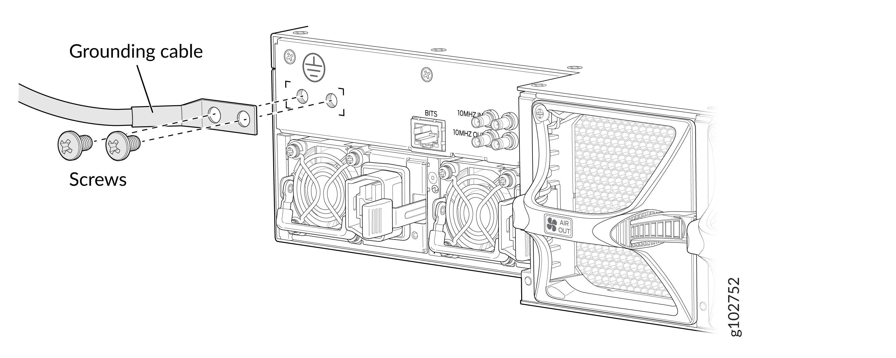
Secure the grounding lug to the protective earthing terminal by using the washers and screws.
Dress the grounding cable and ensure that it does not touch or block access to other device components and that it does not drape where people can trip over it.
Connect the Power Cable and Power On the Router
You must connect each PSU to a dedicated power source outlet.
To connect the power cable and power on the router:
Ensure that the PSU is fully inserted in the chassis and the latches are secure.
Locate the power cord or cords that are appropriate for your geographical location.
Warning:Ensure that the power cords do not block access to router components or drape where people can trip on them.
Insert the coupler end of the power cord into the power cord inlet on the PSU faceplate.
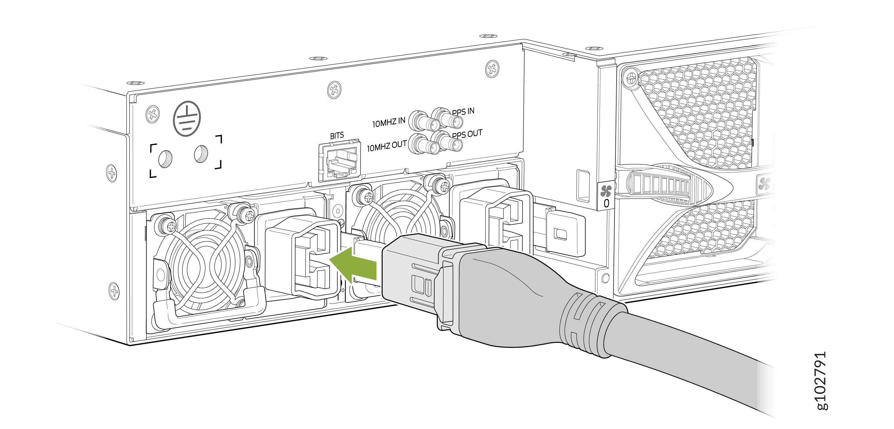
If the power source outlet has a power switch, set it to the off (O) position.
Note:The router powers on as soon as power is provided to the PSU. There is no power switch on the router.
Insert the power cord plug into a power source outlet.
If the power source outlet has a power switch, set it to the on (|) position.
Verify that the status LED on the PSU is lit green. If the status LED is lit amber, remove power from the PSU and replace the PSU (see Remove a Power Supply Unit from the PTX10002-36QDD). Do not remove the PSU until you have a replacement PSU ready.
