PTX10016 Switch Fabric
Switch Interface Boards (SIBs) create the switch fabric for the PTX10016. Each PTX10016 contains up to six SIBs that you can install vertically, mid-chassis, between the line cards and the Routing Control Boards (RCBs) in the front and the fan trays in the rear. When you install six JNP10016-SF SIBs, the PTX10016 has a routing capacity of 96 Tbps. When you install six JNP10016-SF3 SIBs, the PTX10016 has a routing capacity of 565 Tbps.
PTX10016 Switch Interface Board Description
The PTX10016 comes with two models of SIBs:
- The JNP10016-SF SIB has a switching capacity of 14.4 Tbps in one direction and supports Junos OS.
- The JNP10016-SF3 SIB has a switching capacity of 45.9 Tbps in one direction and
supports:
- Junos OS Evolved Release 21.2R2 and later 21.2 releases
- Junos OS Evolved Release 21.4R1 and later
The SIBs make up the PTX10016 routing plane. In configurations that support JNP10016-SF SIBs, five SIBs are required for base operation, and the sixth provides n+1 redundancy. The sixth SIB is powered and available to the system at all times. All six SIBs must be installed and active to deliver full throughput rate of the chassis. With JNP10016-SF3, there is no redundancy for switch fabric. Each of the six switch fabric boards provides one-sixth of the full switching fabric bandwidth. Each SIB has 16 connectors that match and connect to a connector on one of the 16 line cards. See Figure 1.
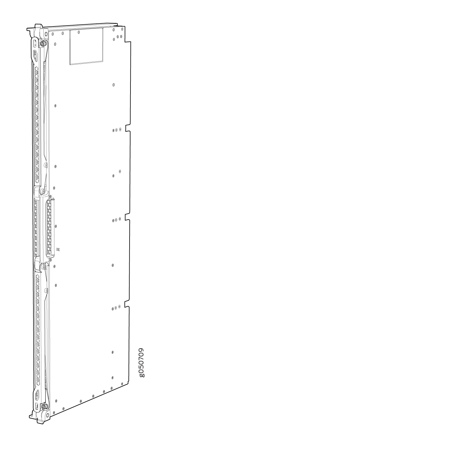

Table 1 lists the physical specifications of a JNP10016-SF SIB. Table 2 lists the physical specifications of a JNP10016-SF3 SIB.
|
Specification |
Value |
|---|---|
|
Height |
34.6 in. (87.88 cm) |
|
Width |
1.8 in. (4.57 cm) |
|
Depth |
13.4 in. (34.04 cm) |
|
Weight |
39.4 lb (17.88 kg) |
|
Specification |
Value |
|---|---|
|
Height |
34.5 in. (87.6 cm) |
|
Width |
1.8 in. (4.57 cm) |
|
Depth |
13.3 in. (33.8 cm) |
|
Weight |
42.7 lb (19.37 kg) |
SIBs are hot-removable and hot-insertable field-replaceable units (FRUs). They are not visible from the outside of the router chassis. You must remove one of the fan trays in order to view the SIBs. The SIBs are numbered from left to right SIB0 to SIB5, with SIB0 located next to the power supplies. See Figure 3.

1 — Fan tray controllers | 2 — SIBs |
See Also
PTX10016 Switch Interface Board LEDs
The SIB has two status LEDs at the top of each board. See Figure 4.

Table 3 describes the functions of these LEDs.
|
Label |
Color |
State |
Description |
|---|---|---|---|
|
PWR (Power) |
Green |
On steadily |
The SIB is receiving power. |
|
Yellow |
Blinking |
Power fault. |
|
|
Unlit |
Off |
The SIB is either offline or not receiving power. |
|
|
STAT (Status) |
Green |
On steadily |
The SIB is online and functioning normally. |
|
Green |
Blinking |
The beacon feature is enabled. |
|
|
Yellow |
On steadily |
The SIB has failed. |
|
|
Unlit |
Off |
The SIB is offline. |