- play_arrow Overview
- play_arrow Site Planning, Preparation, and Specifications
- play_arrow Initial Installation and Configuration
- PTX5000 Installation Overview
- Unpacking the PTX5000
- Installing the PTX5000 in a Rack
- Connecting the PTX5000 Grounding Cable
- Connecting the PTX5000 to AC Power
- Connecting the PTX5000 to DC Power
- Connecting the PTX5000 to External Devices
- Installing the Front Doors on the PTX5000
- Powering the PTX5000 On and Off
- Performing the Initial Software Configuration for the PTX5000
- play_arrow Troubleshooting Hardware
- play_arrow Returning the Chassis or Components
- play_arrow Safety and Compliance Information
- General Safety Guidelines and Warnings
- Definitions of Safety Warning Levels
- Qualified Personnel Warning
- Warning Statement for Norway and Sweden
- Fire Safety Requirements
- Installation Instructions Warning
- Chassis and Component Lifting Guidelines
- Restricted Access Warning
- Ramp Warning
- Rack-Mounting and Cabinet-Mounting Warnings
- Grounded Equipment Warning
- Radiation from Open Port Apertures Warning
- Laser and LED Safety Guidelines and Warnings
- Maintenance and Operational Safety Guidelines and Warnings
- PTX5000 Agency Approvals and Compliance Statements
- General Electrical Safety Guidelines and Warnings
- Action to Take After an Electrical Accident
- Prevention of Electrostatic Discharge Damage
- PTX5000 AC Power Electrical Safety Guidelines
- PTX5000 AC Power Electrical Safety Warnings
- AC Power Disconnection Warning
- PTX5000 DC Power Electrical Safety Guidelines
- DC Power Copper Conductors Warning
- DC Power Disconnection Warning
- DC Power Grounding Requirements and Warning
- DC Power Wiring Sequence Warning
- DC Power Wiring Terminations Warning
- Midplane Energy Hazard Warning
- Multiple Power Supplies Disconnection Warning
- TN Power Warning
Maintaining the PTX5000 Switch Interface Boards
Purpose
For optimum performance, verify the status of the Switch Interface Boards (SIBs).
Action
On a regular basis:
Check the LEDs on the SIB faceplate and craft interface.
During normal operations:
The green OK LED on the SIB faceplate is lit.
The yellow FAIL LED on the SIB faceplate is not lit.
Issue the
show chassis fabric topology
command. During normal operations, the output for the command shows that the state of the online SIBs and FPCs links are in theOK
state.Issue the
show chassis environment sib
command.
Replacing a PTX5000 Switch Interface Board
Replace the PTX5000 Switch Interface Boards (SIBs) by following the procedures described in the following sections.
Removing a PTX5000 Switch Interface Board
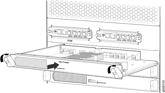
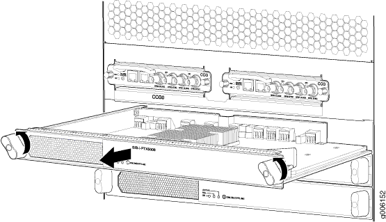
Nine SIBs are installed in the PTX5000. The SIBs are located in the rear of the chassis in the slots marked SIB0 through SIB8. Each SIB can weigh up to 10.4 lb (4.7 kg).
To remove the SIBs (see Figure 1):

Installing a PTX5000 Switch Interface Board
Each SIB can weigh up to 10.4 lb (4.7 kg). To install a SIB (see Figure 2):
