Installing the Front Panel on a QFX10000
The front panel is required on the QFX10008 and QFX10016 to protect fiber optic cabling and to provide additional protection from electromagnetic interference (EMI). The front panel can be installed with or without the optional cable management system.
Ensure you have the following tools and parts before you begin:
A Phillips (+) screwdriver, number 2
Front panel (provided with the switch chassis)
Right base bracket (provided)
Left base bracket (provided)
2 interchangeable latch brackets (provided)
8 Phillips flat-head mounting screws (provided)
To install the front panel:
- Use the Phillips screwdriver to attach two mounting screws
to the left base bracket at the bottom left side of the chassis frame.
The base brackets are larger than the latch brackets.Note:
The right and left base bracket cannot be interchanged (see Figure 1).
Figure 1: Front Panel Mounting Hardware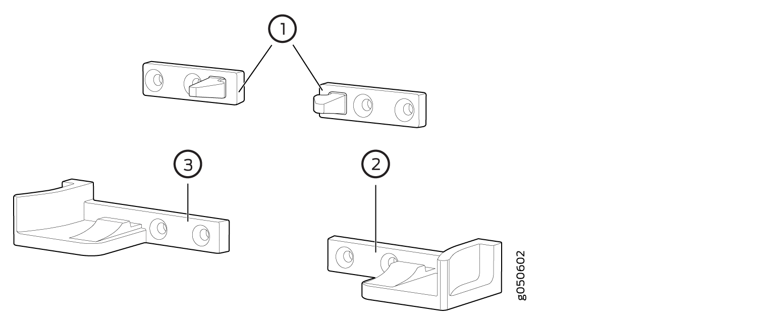 1—
1—Latch brackets
3—Left base bracket
2—Right base bracket
- Use the Phillips screwdriver to attach two mounting screws
to the latch bracket at the top left of the chassis frame (see Figure 2 for QFX10008 and for
QFX10016 installations).Figure 2: Attaching Front Panel Brackets on a QFX10008
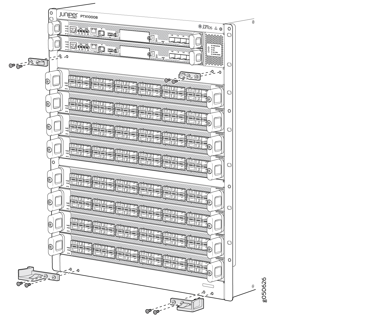 Figure 3: Attaching Front Panel Brackets on a QFX10016
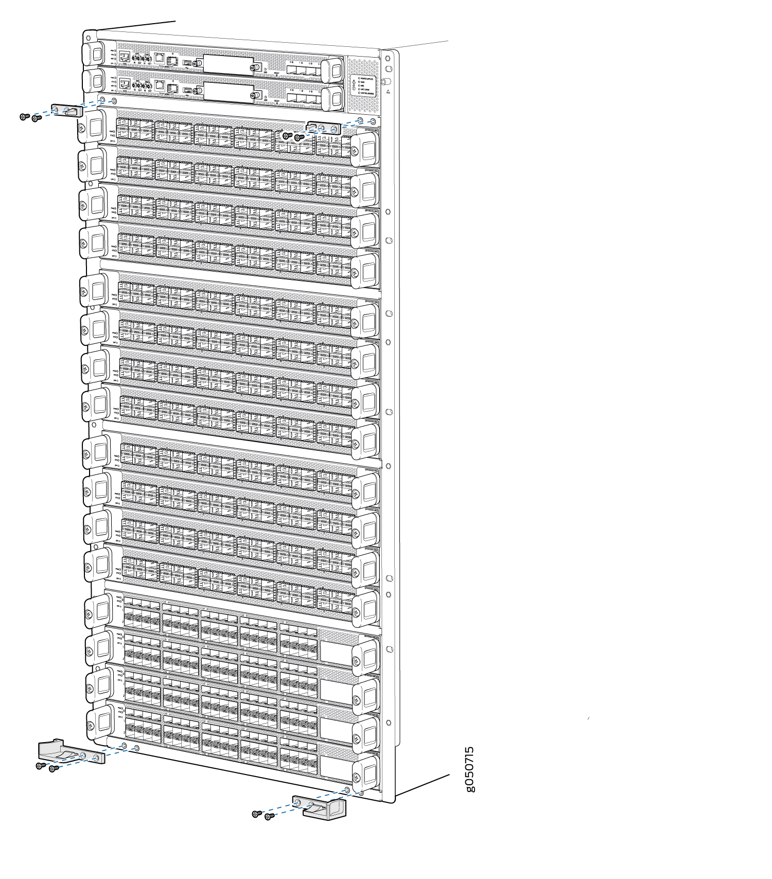
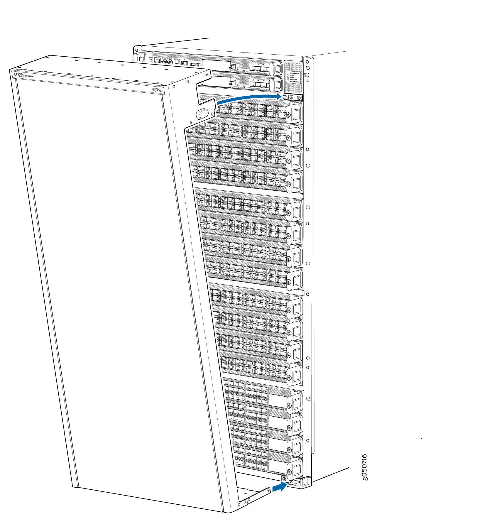
- Tilt the panel towards the chassis until it is vertical
with the chassis. The blue release buttons on the side of the panel
click into place (see Figure 4 for QFX10008 and Figure 5 for QFX10016).Figure 4: Front Panel Installation on a QFX10008
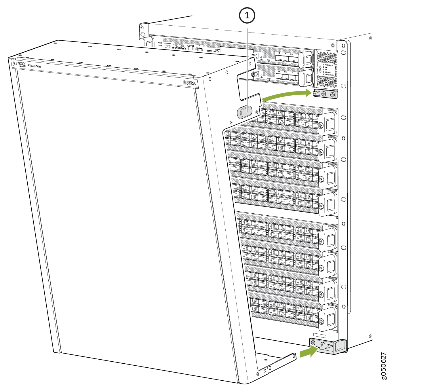 Figure 5: Front Panel Installation on a QFX10016