QFX5120 Chassis
Chassis Physical Specifications for QFX5120 Switches
The QFX5120 switch chassis is a rigid sheet-metal structure that houses all components of the switch. Table 1 shows the physical specifications of the QFX5120 switch models.
Model |
Height |
Width |
Depth |
Weight |
|---|---|---|---|---|
QFX5120-32C |
1.7 in. (4.33 cm) |
17.26 in. (43.84 cm) |
20.27 in. (51.5 cm) excluding fan and power supply handles |
21.12 lb (9.58 kg) with two power supplies and fans installed |
QFX5120-48T |
1.72 in. (4.37 cm) |
|
20.48 in. (52.02 cm) excluding fan and power supply handles |
24.25 lb (11 kg) with two power supplies and fans installed |
QFX5120-48Y |
1.72 in. (4.37 cm) |
|
20.48 in. (52.02 cm) excluding fan and power supply handles |
23.7 lb (10.75 kg) with two power supplies and fans installed |
QFX5120-48YM |
1.72 in. (4.37 cm) |
|
20.48 in. (52.02 cm) excluding fan and power supply handles |
24.8 lb (11.25 kg) with two power supplies and fans installed |
Field-Replaceable Units in QFX5120 Switches
Field-replaceable units (FRUs) are components that you can replace at your site. The FRUs in QFX5120 switches are hot-removable and hot-insertable: You can remove and replace them without powering off the switch or disrupting switch functions. The QFX5120 switches have the following FRUs:
Power supplies
Fan modules
Transceivers
Transceivers are not part of the shipping configuration. If you want to purchase any of these components, you must order them separately.
If you have a Juniper J-Care service contract, register any addition, change, or upgrade of hardware components at https://www.juniper.net/customers/support/tools/updateinstallbase/. Failure to do so can result in significant delays if you need replacement parts. This note does not apply if you replace existing components with the same type of component.
Chassis Status LEDs in QFX5120 Switches
The rear panel of QFX5120-32C switches has a chassis ID LED labeled ID (see Figure 1).
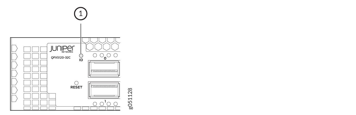
1 — Chassis ID LED (labeled ID) |
Table 2 describes the chassis ID LED on QFX5120-32C switches, its color and states, and the status they indicate.
|
LED Label |
Color |
State and Description |
|---|---|---|
|
ID |
Yellow |
Blinking—The beacon feature is enabled on the switch. |
|
Unlit |
The beacon feature is not enabled on the switch. You
can enable the beacon feature by using the |
The rear panel of QFX5120-48T, QFX5120-48Y, and QFX5120-48YM switches has four chassis status LEDs labeled ALM, SYS, MST, and ID (see Figure 2, Figure 3, and Figure 4).
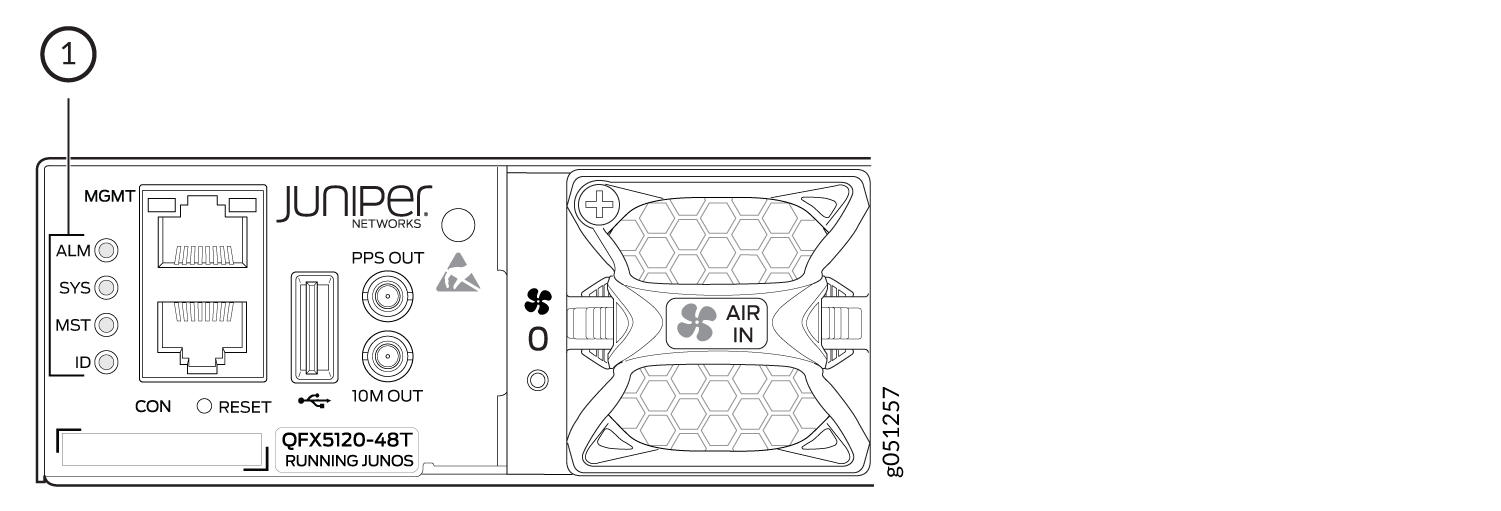
1 — Chassis status LEDs (labeled ALM, SYS, MST, and ID) |
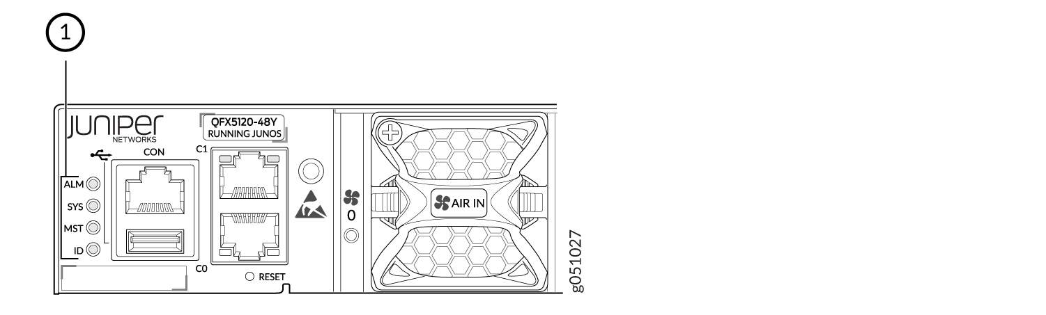
1 — Chassis status LEDs (labeled ALM, SYS, MST, and ID) |
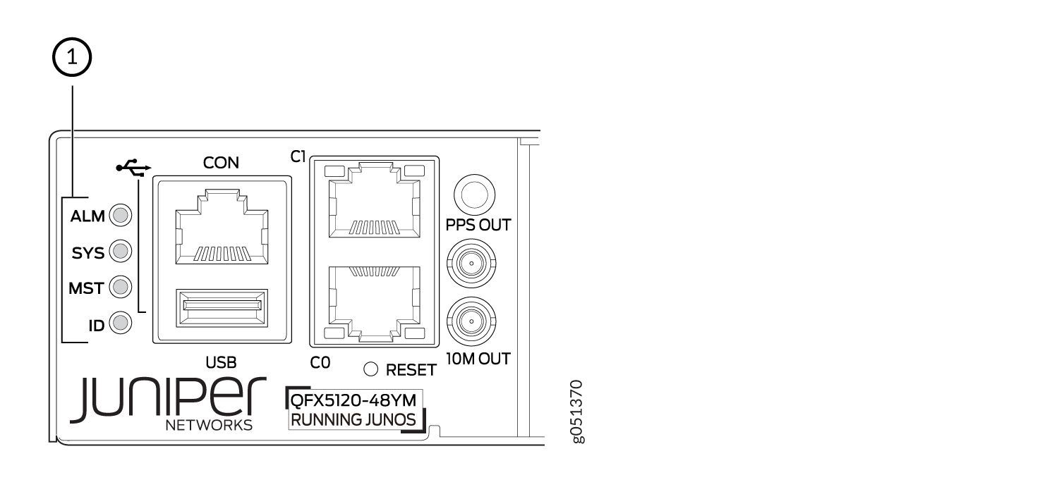
1 — Chassis status LEDs (labeled ALM, SYS, MST, and ID) |
Table 3 describes the chassis status LEDs on QFX5120-48T, QFX5120-48Y, and QFX5120-48YM switches, their colors and states, and the status they indicate.
|
LED Label |
Color |
State and Description |
|---|---|---|
|
ALM |
Red |
There is a major hardware fault, such as a temperature alarm or a power failure alarm, and the switch is halted. A major alarm indicates a critical error condition that requires immediate action. See Chassis Component Alarm Conditions on QFX5120 Switches. |
|
Yellow |
There is a minor alarm such as a software or a hardware error. Power off the switch and then power it on. Monitor the switch to see if it is working properly. A minor alarm indicates a noncritical condition that requires monitoring or maintenance. A minor alarm that is left unchecked might cause interruption in service or performance degradation. |
|
|
Unlit |
There is no alarm or the switch is halted. |
|
|
SYS |
Green |
On steadily—Junos OS for QFX Series switches is loaded on the switch. |
|
Blinking—The switch is a member in a QFX Series Virtual Chassis configuration. |
||
|
Unlit |
The switch is powered off or is halted. |
|
|
MST |
Green |
In a standalone QFX5120 switch: On steadily—The switch is functioning normally as the primary switch. |
|
In a Virtual Chassis configuration:
|
||
|
Unlit |
|
|
|
ID |
Blue |
Blinking—The beacon feature is enabled on the switch. |
|
Unlit |
The beacon feature is not enabled on the switch. You
can enable the beacon feature by using the |
LEDs on the Management Port on QFX5120 Switches
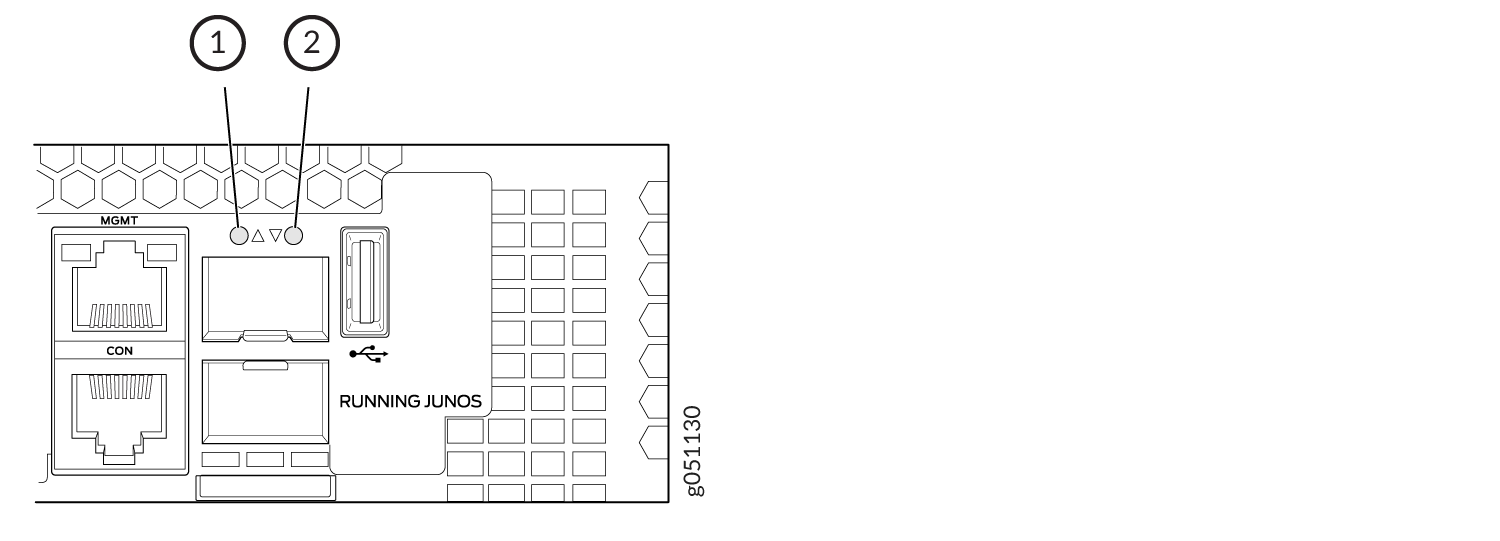
QFX5120-32C switches have one management port on the front panel. Figure 5 shows the location of the management port on the QFX5120-32C and the LED on the port. The LED indicates link activity of the port. Table 4 describes the LED on the management port on QFX5120-32C switches.
QFX5120-48T switches have one management port on the rear panel. Figure 6 shows the location of the management port on the QFX5120-48T and the LEDs on the port. The LEDs indicate link activity and status of the port. Table 5 describes the LEDs on the management port on QFX5120-48T switches.
QFX5120-48Y switches have two management ports on the rear panel. Figure 7 shows the location of the management ports on the QFX5120-48Y and the LEDs on the ports. The LEDs indicate link activity and status of the port. Table 5 describes the LEDs on the management ports on QFX5120-48Y switches.
QFX5120-48YM switches have two management ports on the rear panel. Figure 8 shows the location of the management ports on the QFX5120-48YM and the LEDs on the ports. The LEDs indicate link activity and status of the port. Table 5 describes the LEDs on the management ports on QFX5120-48YM switches.
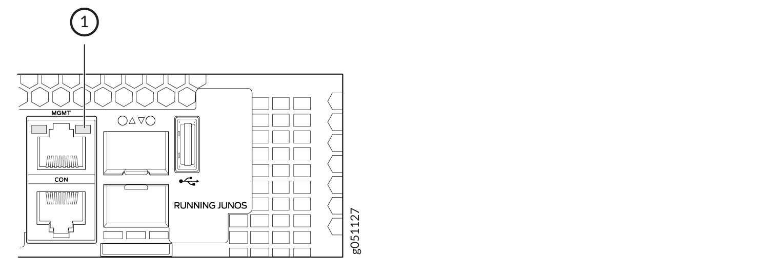
1 — Link activity LED |
|
LED |
Color |
State and Description |
|---|---|---|
|
Link activity |
Green |
On steadily—The port and the link are active, but there is no link activity. |
|
Blinking—The port and the link are active and there is link activity. |
||
|
Unlit |
The port is administratively disabled, there is no power, the link is down, or there is a fault. |
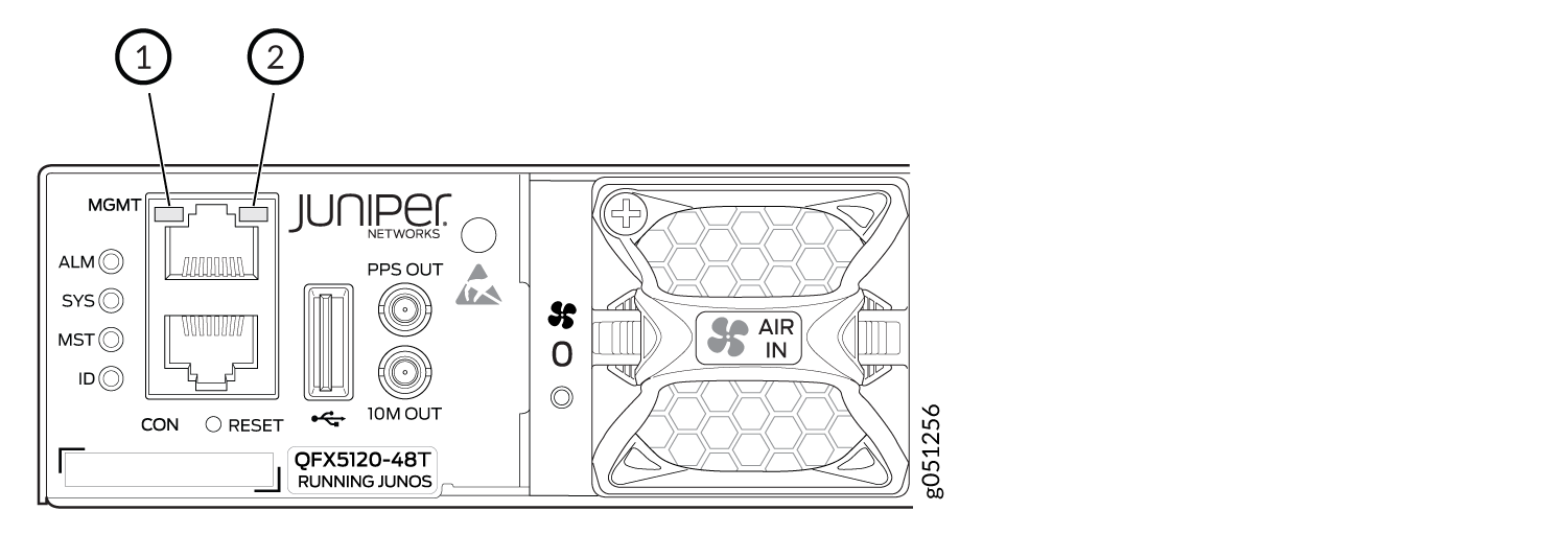
1 — Status LED | 2 — Link activity LED |
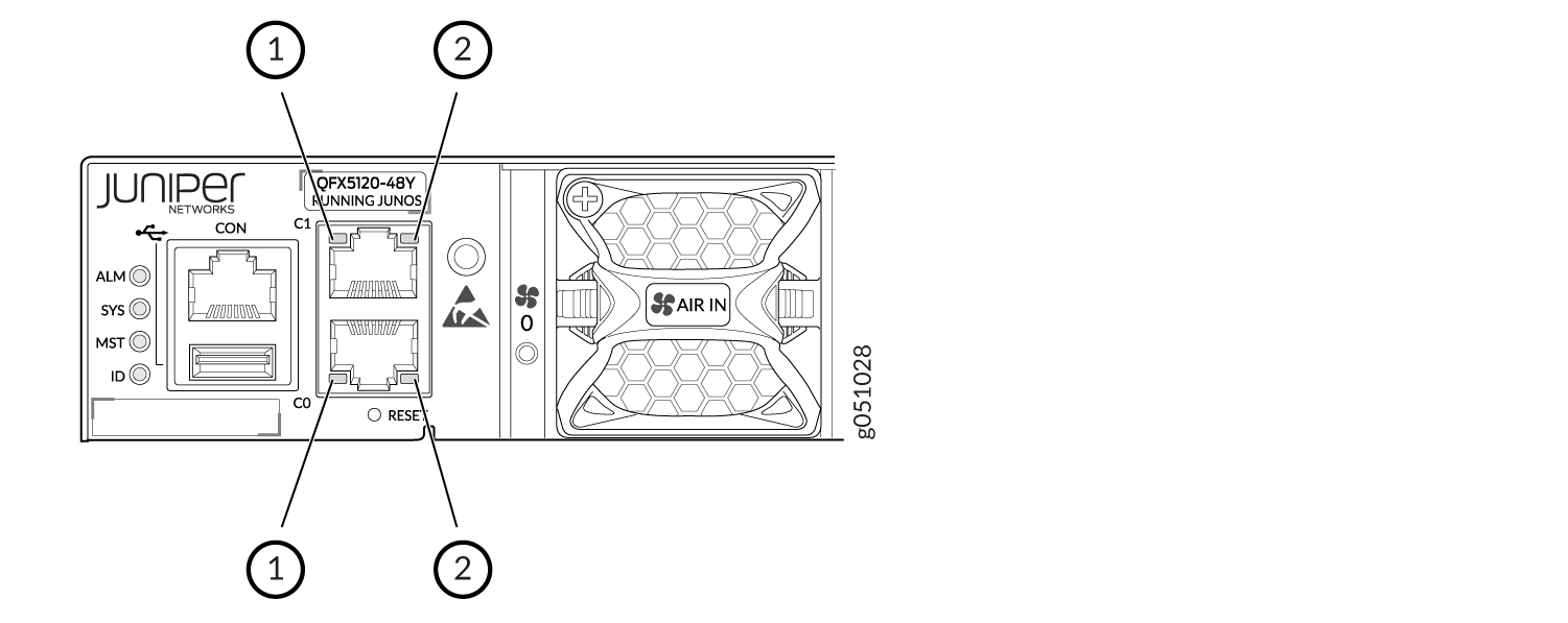
1 — Status LED | 2 — Link activity LED |
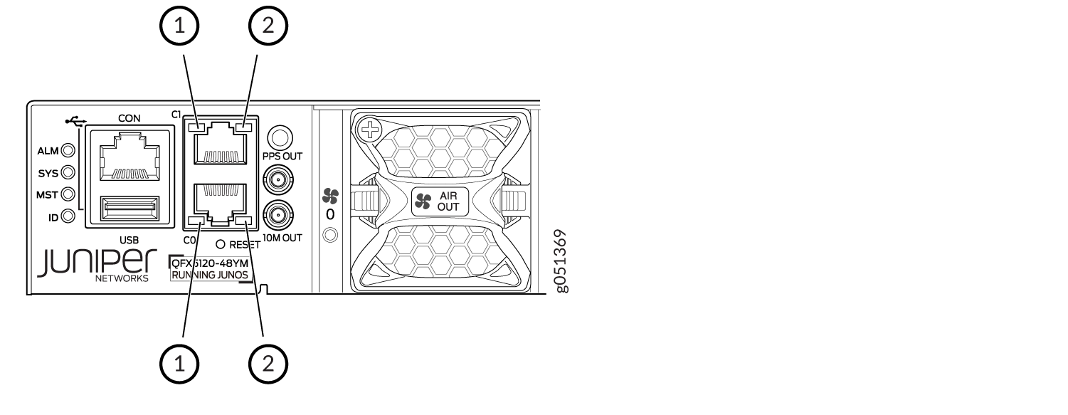
1 — Status LED | 2 — Link activity LED |
|
LED |
Color |
State and Description |
|---|---|---|
|
Link activity |
Green |
On steadily—The port and the link are active, but there is no link activity. |
|
Blinking—The port and the link are active and there is link activity. |
||
|
Unlit |
The port is administratively disabled, there is no power, the link is down, or there is a fault. |
|
|
Status |
Green |
On steadily—The link speed is 1000 Mbps. |
|
Yellow |
On steadily—The link speed is 100 Mbps. |
|
|
Unlit |
Either the port speed is 10 Mbps or the link is down. |
Network Port LEDs on QFX5120 Switches
- Network Port LEDs on QFX5120-32C Switches
- Network Port LEDs on QFX5120-48T Switches
- Network Port LEDs on QFX5120-48Y Switches
- Network Port LEDs on QFX5120-48YM Switches
Network Port LEDs on QFX5120-32C Switches
Each SFP+ port on QFX5120-32C switches has one LED that shows the link activity of the port (see Figure 9). See Table 6 to learn more about that LED.
Each QSFP28 port on QFX5120-32C switches has four LEDs that show the link activity of the port (see Figure 10). The first LED operates when the port is not channelized; the other three LEDs operate when the port is channelized. See Table 7 to learn more about those LEDs.
1 — LED for the SFP+ port 32 | 2 — LED for the SFP+ port 33 |
|
Color |
State and Description |
|---|---|
|
Green |
On steadily—The port and the link are active, but there is no link activity. |
|
Blinking—The port and the link are active and there is link activity. |
|
|
Unlit |
The port is not active. |
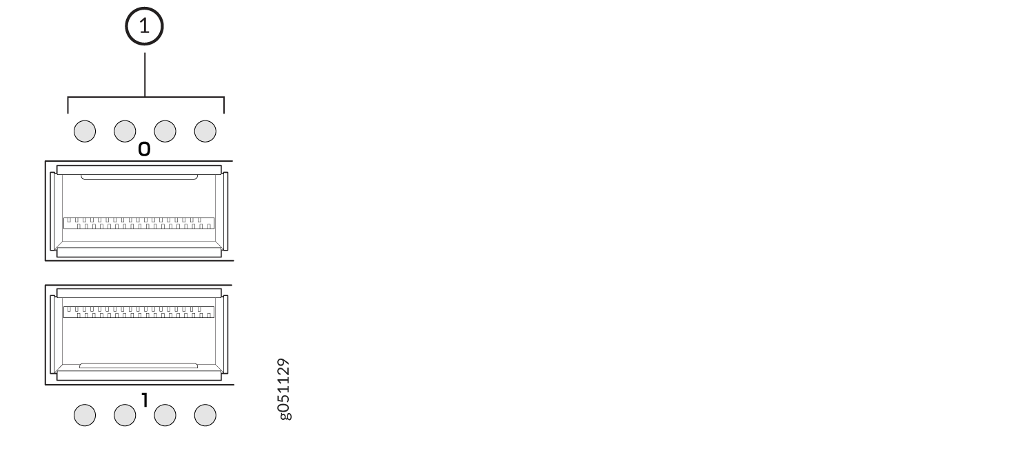
1 — LEDs on the QSFP28 ports |
|
Position |
Color |
State |
Description |
|---|---|---|---|
|
1 |
Green |
On steadily |
The port is not channelized, a 100 -Gbps or 40 -Gbps link is established, but there is no link activity. When this LED is on, the LEDs in positions 2 through 4 are off. |
|
Blinking |
The port is not channelized, a 100 -Gbps or 40 -Gbps link is established, and there is link activity. |
||
|
1–4 |
Green |
On steadily |
The port is channelized, a 25-Gbps or 10-Gbps link is established, but there is no link activity. |
|
Blinking |
The port is channelized, a 25-Gbps or 10-Gbps link is established, and there is link activity. |
||
|
1–4 |
Unlit |
Unlit |
The port is administratively disabled, there is no power, the link is down, or there is a fault. |
Network Port LEDs on QFX5120-48T Switches
Each BASE-T port on QFX5120-48T switches has one LED that indicates the status of the port (see Figure 11). See Table 8 to learn more about that LED.
Each QSFP28 port on QFX5120-48T switches has one LED that indicates the status of the port (see Figure 12). See Table 9 to learn more about that LED.
1 — LED for the BASE-T ports in the top row | 2 — LED for the BASE-T ports in the bottom row |
|
Color |
State and Description |
|---|---|
|
Green |
On steadily—The port is operating at 10-Gbps speed, but there is no link activity. |
|
Blinking—The port is operating at 10-Gbps speed and there is link activity. |
|
|
Yellow |
On steadily—The port is operating at 1-Gbps speed, but there is no link activity. |
|
Blinking—The port is operating at 1-Gbps speed and there is link activity. |
|
|
Blipping—The beacon function is enabled on the port. |
|
|
Unlit |
The port is administratively disabled, there is no power, the link is down, or there is a fault. |
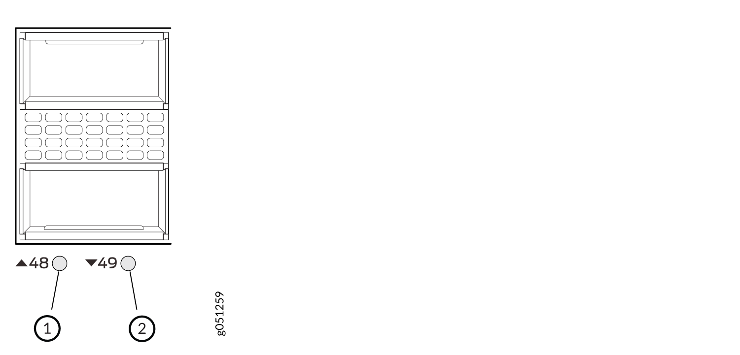
1 — LED for the QSFP28 ports in the top row | 2 — LED for the QSFP28 ports in the bottom row |
|
Color |
State and Description |
|---|---|
|
Green |
When the port is not channelized and is configured to operate as one 100GbE or 40GbE interface:
|
|
When the port is channelized and is configured to operate as two 50GbE interfaces:
|
|
|
When the ports 50 and 51 are channelized and are configured to operate as four 25GbE or 10GbE interfaces:
|
|
|
Yellow |
When the port is channelized and is configured to operate as two 50GbE interfaces:
|
|
Unlit |
The port is administratively disabled, there is no power, the link is down, or there is a fault. |
Network Port LEDs on QFX5120-48Y Switches
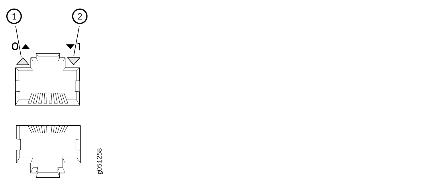
Each SFP28 port on QFX5120-48Y switches has two LEDs that show the link activity and status of the port (see Figure 13). See Table 10 to learn more about those LEDs.
Each QSFP28 port on QFX5120-48Y switches has four LEDs that show the link activity of the port (see Figure 14). The first LED operates when the port is not channelized; the other three LEDs operate when the port is channelized. See Table 11 to learn more about those LEDs.
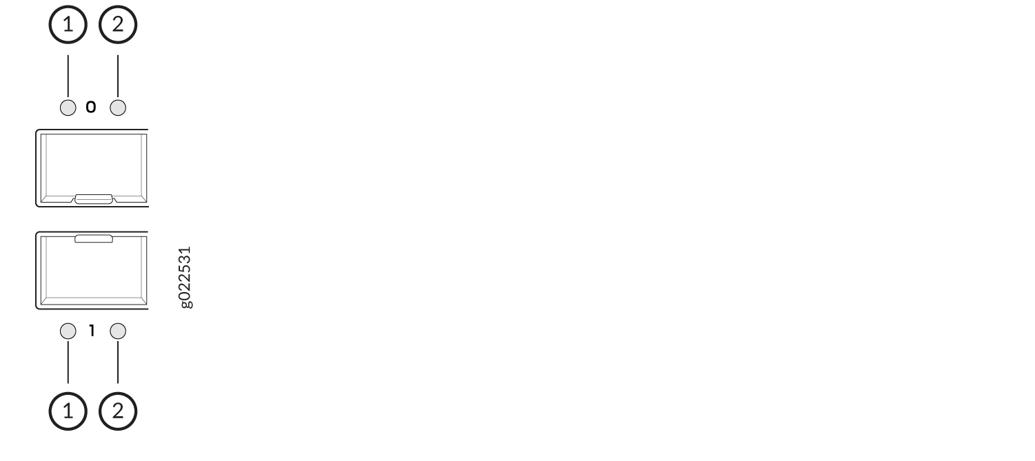
1 — Link activity LED for the SFP28 ports | 2 — Status LED for the SFP28 ports |
|
LED |
Color |
State and Description |
|---|---|---|
|
Link activity |
Green |
On steadily—The port and the link are active, but there is no link activity. |
|
Blinking—The port and the link are active and there is link activity. |
||
|
Unlit |
The port is not active. |
|
|
Status |
Green |
On steadily—The port is operating at 25-Gbps speed. |
|
Blinking—The port is operating at 1-Gbps or 10-Gbps speed. |
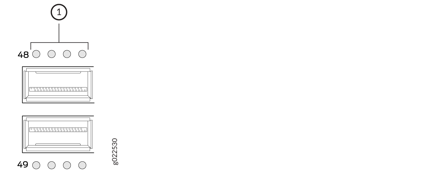
1 — LEDs on the QSFP28 ports in the top row |
|
Position |
Color |
State |
Description |
|---|---|---|---|
|
1 |
Green |
On steadily |
The port is not channelized, a 100 Gbps or 40 Gbps link is established, but there is no link activity. When this LED is on, the LEDs in positions 2 through 4 are off. |
|
Blinking |
The port is not channelized, a 100 Gbps or 40 Gbps link is established, and there is link activity. |
||
| 1–4 |
Green |
On steadily |
The port is channelized, a 25-Gbps or 10-Gbps link is established, but there is no link activity. |
|
Blinking |
The port is channelized, a 25-Gbps or 10-Gbps link is established, and there is link activity. |
||
|
All |
Yellow |
Blinking |
The beacon function is enabled on the port. |
|
1–4 |
Unlit |
Unlit |
The port is administratively disabled, there is no power, the link is down, or there is a fault. |
Network Port LEDs on QFX5120-48YM Switches
Each SFP28 port on QFX5120-48YM switches has one LED that shows the link activity and status of the port (see Figure 15). See Table 12 to learn more about that LED.
Each QSFP28 port on QFX5120-48YM switches has one LED that shows the link activity and status of the port (see Figure 16). See Table 13 to learn more about those LEDs.
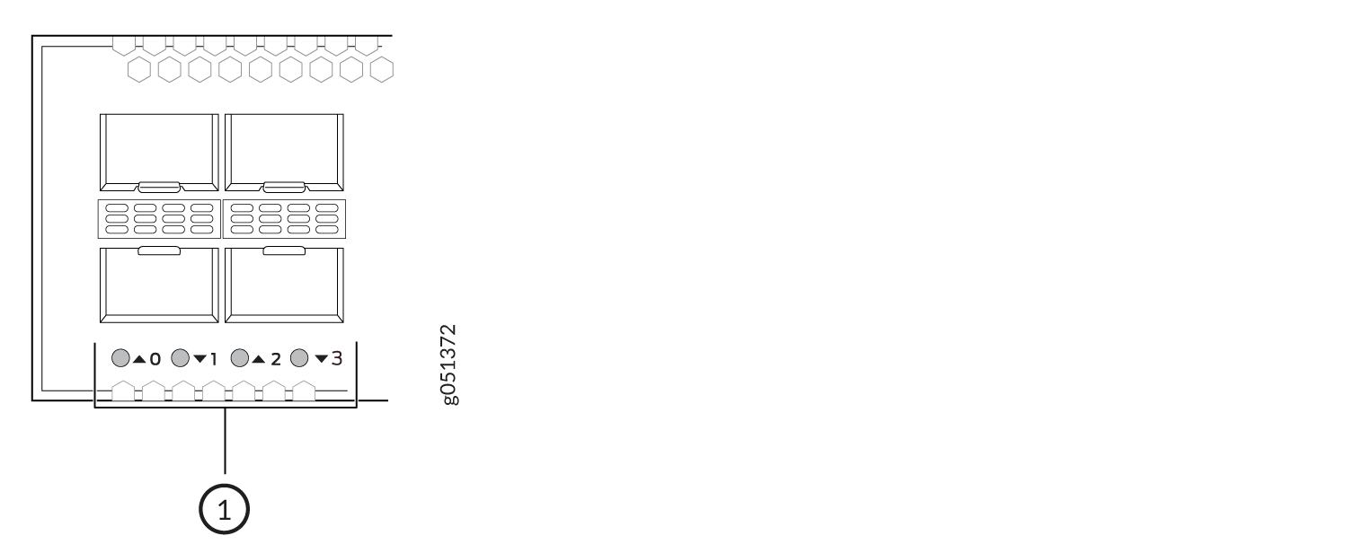
1 — LED on the SFP28 ports on QFX5120-48YM switches |
|
Color |
State and Description |
|---|---|
|
Green |
On steadily—A link is established, but there is no link activity. |
|
Blinking—A link is established and there is link activity. |
|
|
Yellow |
Blinking—The beacon function is enabled on the port. |
|
Unlit |
The port is administratively disabled, there is no power, the link is down, or there is a fault. |
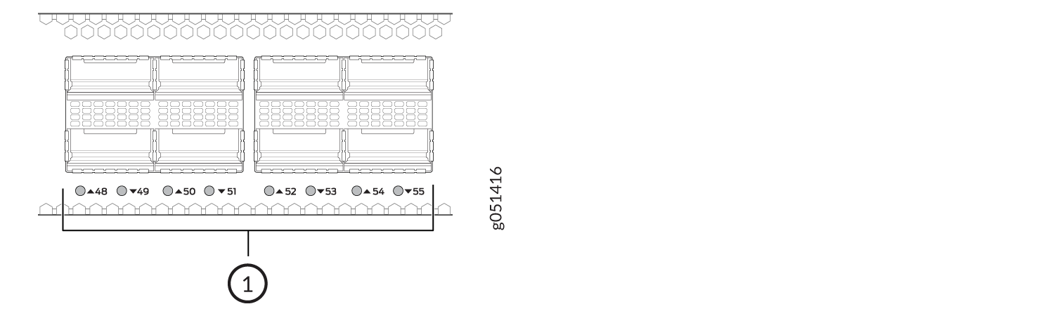
1 — LED on the QSFP28 ports on QFX5120-48YM switches |
|
Color |
State |
Description |
|---|---|---|
|
Green |
On steadily |
A link is established, but there is no link activity. |
|
Blinking |
A link is established and there is link activity. |
|
|
Yellow |
Blinking |
The beacon function is enabled on the port. |
|
Unlit |
Unlit |
The port is administratively disabled, there is no power, the link is down, or there is a fault. |