QFX5230-64CD Cooling System
QFX5230-64CD Cooling System Description
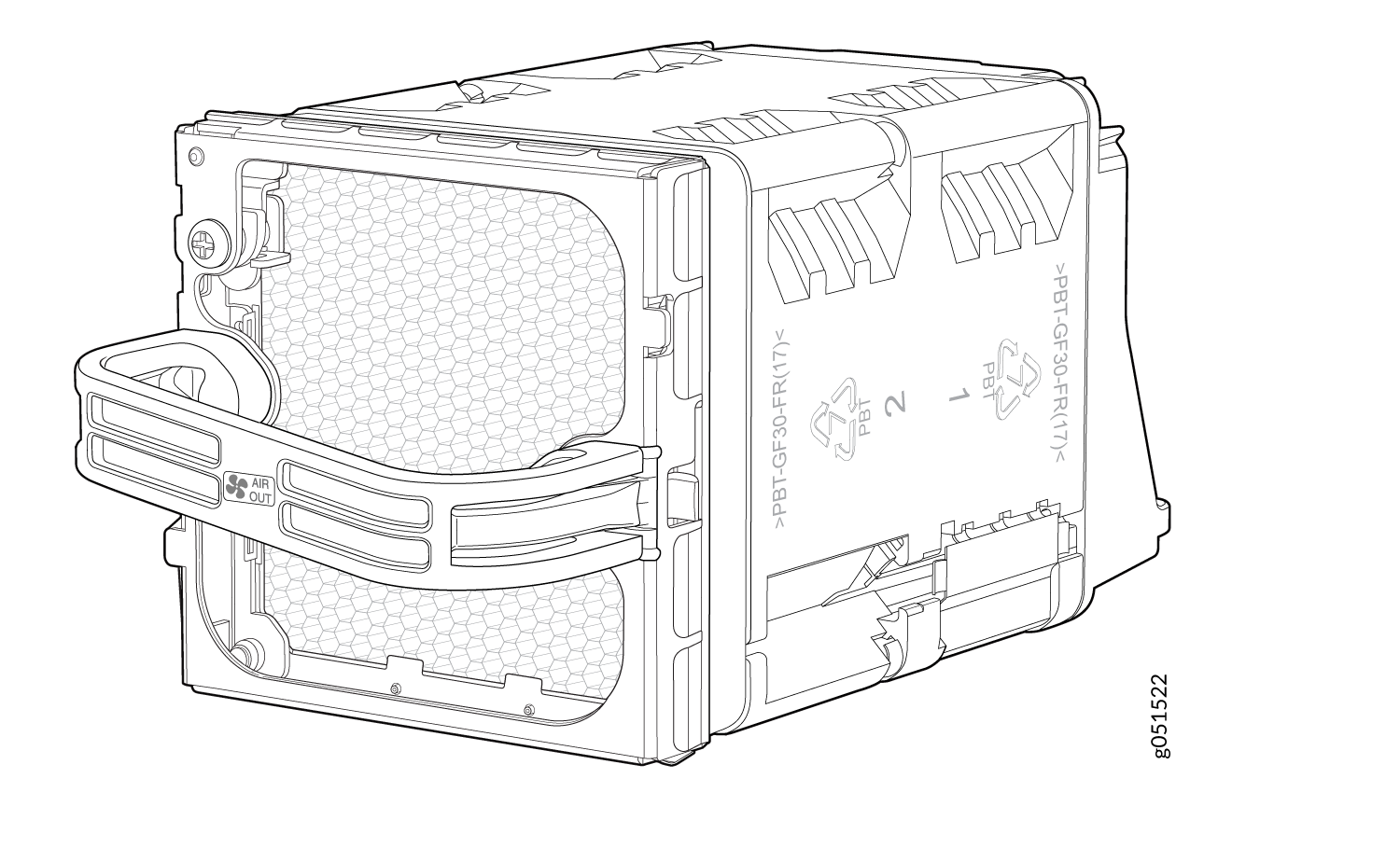
The cooling system in a QFX5230-64CD switch consists of eight fans in four modules. Each fan module contains two rotors. The fan modules are hot-insertable and hot-removable FRUs with airflow direction and color coding. Each fan module houses two 80mm x 86mm counter rotating rotors.
The fan modules in a QFX5230-64CD are hot-removable and hot-insertable FRUs designed for port-to-FRU airflow and FRU-to-port airflow. The fan modules are numbered from 0 to 3 . Each fan module is 2 U high and has an associated LED to indicate status.
Fan Modules
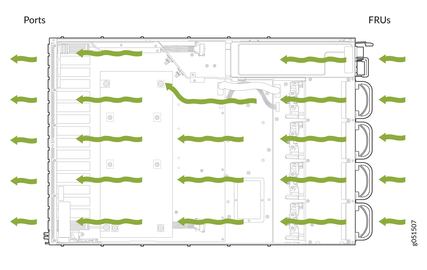
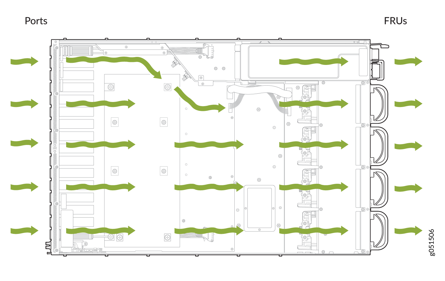
The QFX5230-64CD switch is intended for both front to back (AFO) and back to front (AFI) airflow. The switch can be ordered in one of two airflow directions:
Airflow In - Air enters the switch via the vents in the field-replaceable units (FRUs) on the back side.
Airflow Out - Air enters the switch through the port panel vents.
For front-to-back air flow, fan modules plugged into the rear side of the chassis suck air out of the system. To allow for air inlet, vents are provided in the front panel. For back-to-front airflow, fan modules plugged into the chassis's rear side push air into the system, and vents provided in the front panel allow for air outlet. There are two 80mm x 86mm counter rotating rotors inside each fan module. The system can handle a single rotor failure. Any additional fan/rotor failure causes the switch to overheat, triggering chassis alarms and shutting down the switch.
|
FAN FRUs |
Description |
Airflow |
Color |
|---|---|---|---|
| QFX5230-64CD-FANAO | AIR OUT, port-to-FRU airflow | Front - Back |
Juniper Gold |
| QFX5230-64CD-FANAI | AIR IN, FRU-to-port airflow | Back - Front | Green |
Fan speed varies based on the temperature of internal components, optics module, and ambient temperature. The maximum speed at which fans operate depends on the configured ambient temperature. As the fan speed increases, the power consumed by the fans increases. As a result, the device consumes more power when the temperature is high because the fans run faster to maintain the operating temperature of the chassis within the configured limits.
The fan modules are available in two models that have different airflow directions:
The QFX5230-64CD switches that support airflow out (AIR OUT) bring air into the vents in the port panel and exhausts warmed air through the field-replaceable units (FRU) panel. This type of airflow is known as airflow out or port-to-FRU airflow. Airflow out fans are distinguished by AIR OUT marking on the gold-colored handles. In data center deployments, position the switch in such a manner that the AIR OUT labels on the switch components are next to the hot aisle.
The QFX5230-64CD switches that support airflow in (AIR IN) bring air into the vents in the field-replaceable units (FRU) panel and exhausts warmed air through the port panel. This type of airflow is known as airflow in or FRU-to-port airflow. Airflow in fans are distinguished by AIR IN marking on the green-colored handles. In data center deployments, position the switch in such a manner that the AIR IN labels on the switch components are next to the cold aisle.You remove and replace a fan module from the FRU end of the chassis. The switch continues to operate for a limited period of time (120 seconds) during the replacement of the fan module before thermal shutdown.
QFX5230-64CD Fan Module LED
The following figure shows the fan module LED for QFX5230-64CD.
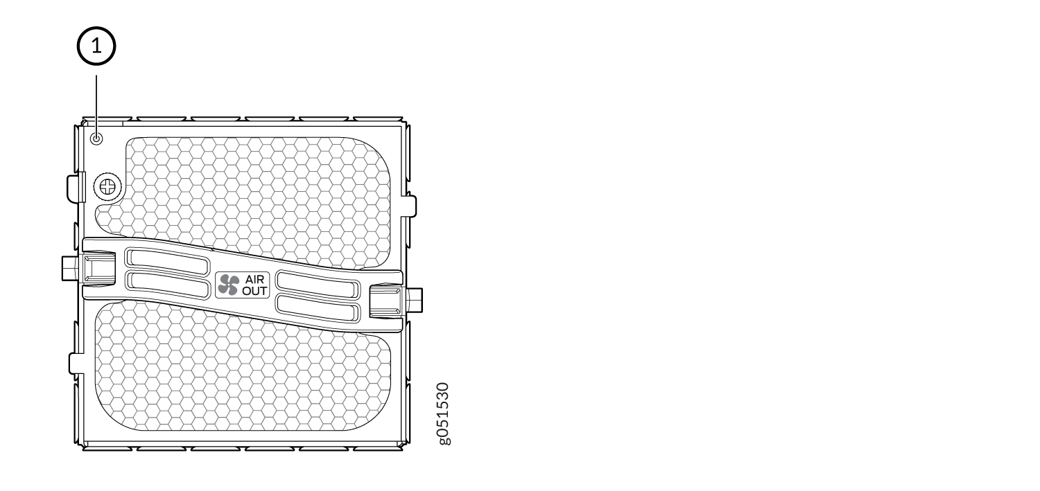
-
Fan module LED
Under normal operating conditions, the fan modules operate at a moderate speed. Temperature sensors in the chassis monitor the temperature within the chassis.
The system raises an alarm if a fan module fails or if the ambient temperature inside the chassis rises above the acceptable range. If the temperature inside the chassis rises above the threshold temperature, the system shuts down automatically.