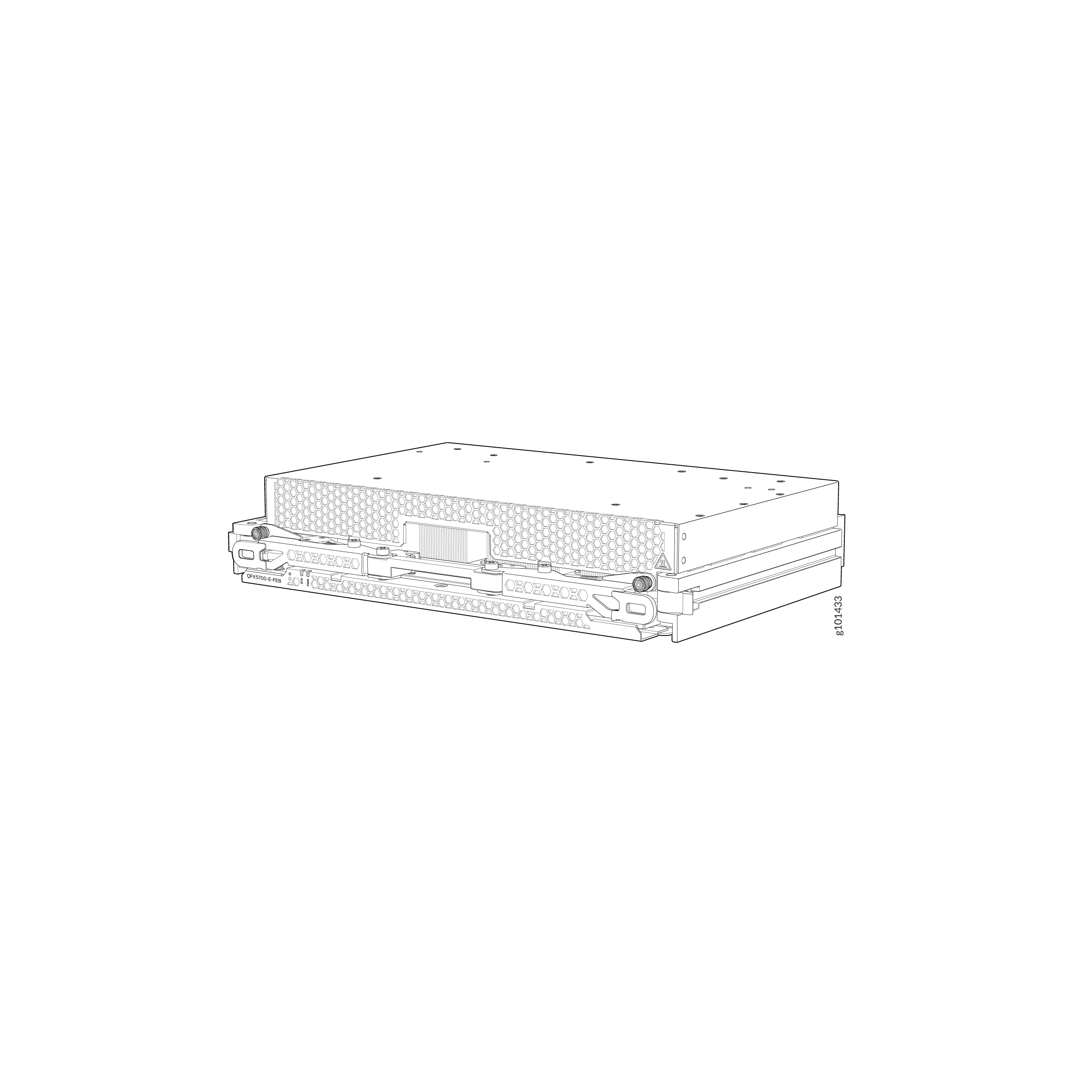
QFX5700 Forwarding Engine Board
QFX5700 switch supports one QFX5700-FEB/QFX5700E-FEB Forwarding Engine Board (FEB) that is installed horizontally, mid-chassis, between the Flexible PIC Concentrators (FPCs) and the Routing Control Board (RCB) in the front and the fan trays in the rear. The FEB is not visible from the outside of the switch chassis. You must remove one of the fan trays to see the FEB.
The FEB and FPC is interconnected using the Direct Ortho Connector.
The QFX5700 design is accomplished with a Packet Processing and Traffic Management TD4 chipset. The TD4 chipset handles a full duplex 12.8Tbps data at the Fabric Interface for non-blocking switching operations.
The QFX5700 uses 1 FEB and 8 FPC slots (0-7) to connect 256 SerDes links from each FEB card to respective FPC slots (32 SerDes/slot). Each FPC slot is capable of driving 1.6Tbps data (based on slot numbers) to WAN ports.
QFX5700-FEB/QFX5700E-FEB Specifications
The QFX5700-FEB/QFX5700E-FEB specifications include the following:
|
Specification |
QFX5700-FEB |
|---|---|
|
Software release |
Junos OS Evolved 21.2R2 |
|
Supported FPCs |
|
|
Height |
8.4 cm |
|
Width |
43.7 cm |
|
Depth |
28.1 cm |
|
Weight |
6.6 kg |
|
Power Requirement |
300W |
QFX5700-FEB/QFX5700-E FEB LEDs
The Forwarding Engine Boards (FEBs) have two status LEDs. See Figure 2.
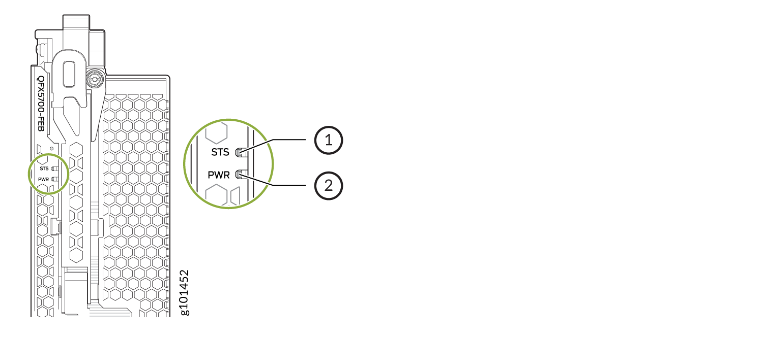
1 — Status LED | 2 — Power LED |
This table describes the functions of FEB LEDs and the Online/Offline button.
| Label | Color | State | Description |
|---|---|---|---|
|
PWR (Power) |
Green |
On steadily |
The FEB is receiving power. |
|
Yellow |
On steadily |
The FEB is receiving power but a power fault occurred. |
|
|
Dark |
Off |
The FEB is either offline or not receiving power. |
|
|
STS (Status) |
Green |
On steadily |
The FEB is online and functioning normally. |
|
Blinking |
The FEB is booting or going offline. |
||
|
Yellow |
On steadily |
The FEB has failed. |
|
|
Dark |
Off |
The FEB is offline. |
|
|
Online/Offline button |
- |
- |
You can use this button to power on/off the FEB. |