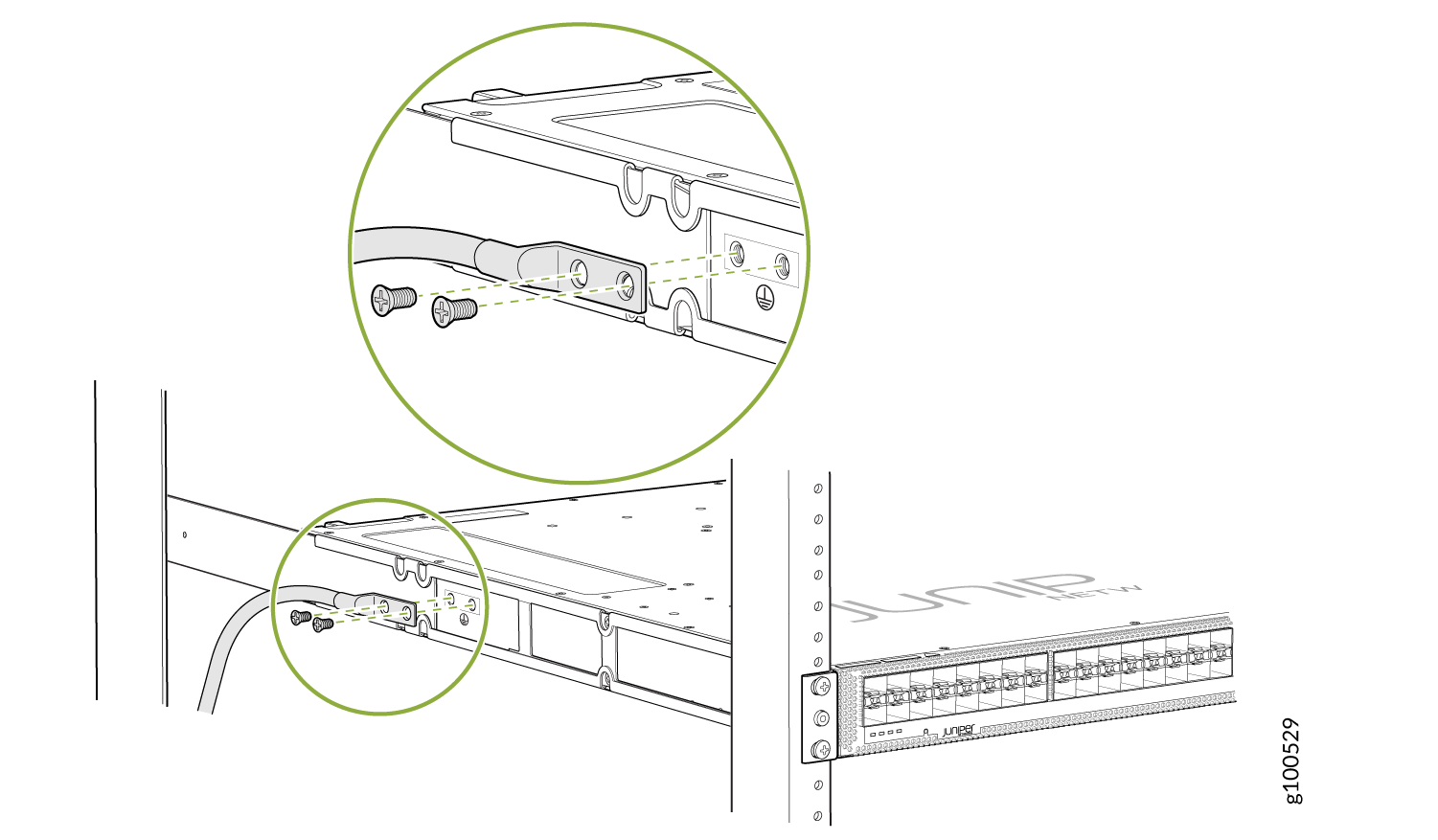
Step 3: Connect the Grounding Cable
To meet safety and electromagnetic interference (EMI) requirements and to ensure proper operation, you must ground the router properly before connecting power.
Figure 1, Figure 2, and Figure 3 show the grounding points on ACX5400 routers.


1 — Grounding points |
You need a protective earthing terminal bracket for connecting the chassis to earth ground. This two-holed bracket attaches on the side of the chassis through the mounting rail and provides a protective earthing terminal for the router. The grounding points are in the form of studs sized for #10–32 pan head screws. (You need to provide these screws with integrated washers as we do not ship them in the accessory kit). The grounding points are spaced at 0.63-in. (16-mm) centers.
You ground the router by connecting a grounding cable to earth ground and then attaching it to the chassis grounding points by using two #10–32 pan head screws. You must provide the grounding cables.
The grounding lug required is a Panduit LCD10-10A-L or equivalent (not provided). The grounding lug accommodates 12 AWG (2.5 mm²) stranded wire. The grounding cable that you provide for the chassis must be the same size or heavier than the input wire of each PSM. We recommend the following minimum standards:
12 AWG (2.5 mm²), 60° C temperature-rated stranded wire for the ACX5448 router.
12 AWG (2.5 mm²), 90° C temperature-rated stranded wire for the ACX5448-D and ACX5448-M routers
To ground the ACX5400 router:


