Help us improve your experience.

Let us know what you think.

Do you have time for a two-minute survey?


Step 1: Begin

In this guide, we provide a simple, three-step path, to quickly get you up and running with the Juniper Networks® ACX7509 Cloud Metro Router. You'll learn how to install, power on, and configure basic settings for an AC-powered ACX7509 router.

If you need instructions to install a DC-powered ACX7509, see the ACX7509 Router Hardware Guide.

Meet the ACX7509

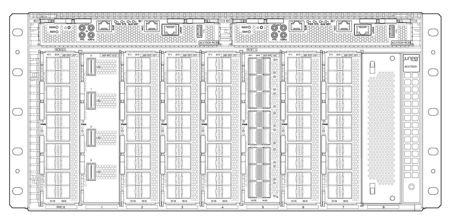
The ACX7509 Cloud Metro Router is a high-performance and fully redundant (control plane and data plane) high-end aggregation router which supports IP services to service providers, web and enterprise networks. The ACX7509 also comes with several other capabilities that include segment routing, advanced timing, flexible licensing and a comprehensive set of features that are suited for 5G and cloud metro architectures.

You can use either Paragon Automation or the device CLI to deploy the ACX7509 Router to the network.

The ACX7509 router with a 5-U form factor (occupies 6-U rack space with the cable management system) provides a throughput of 4.8 Tbps while maintaining a power-efficient footprint. It supports three types of Flexible PIC Concentrators (FPCs) which offer 1GbE, 10GbE, 25GbE, 40GbE, 50GbE, 100GbE, 200GbE, and 400GbE port speeds and MACsec–ready ports.
Install the ACX7509

What's in the Box?

Along with your ACX7509, you’ll also find:

  • An accessory kit which includes:

    • Warranty card

    • Media kit (USB flash drivers)

    • RJ-45 Y-splitter cable

    • AC power cord (country specific)

    • Electrostatic discharge (ESD) wrist strap with cable

What Else Do I Need?

You’ll need:

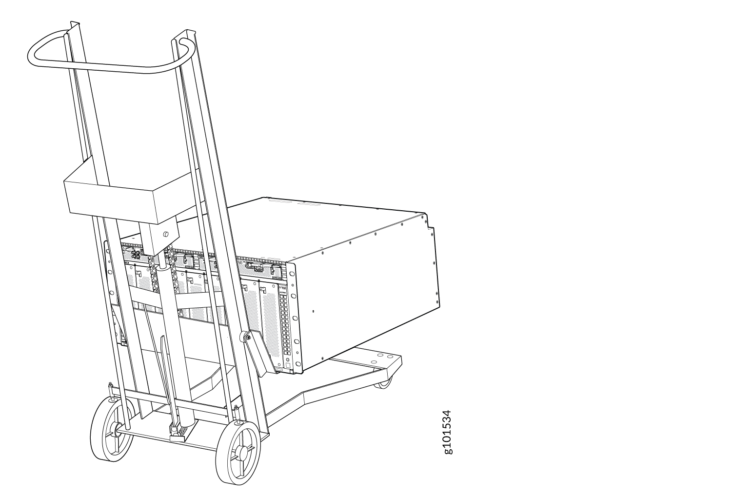
  • A mechanical lift rated for 250 lb (113.4 kg) to mount the router

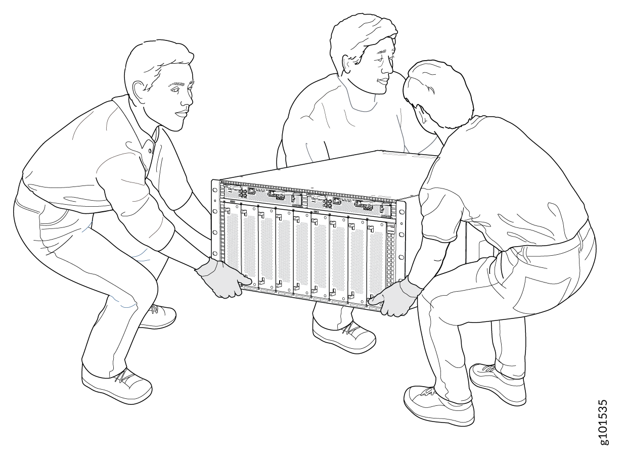
  • Three people to help you secure the router to the rack

  • A Phillips (+) screwdriver, number 2 or number 3, depending on the size of your rack-mount screws

  • RJ-45 Ethernet cable and RJ-45 to DB-9 serial port adapter

    Note:

    We no longer include the RJ-45 console cable with the DB-9 adapter as part of the device package. If the console cable and adapter are not included in your device package, or if you need a different type of adapter, you can order the following separately:

    • RJ-45 to DB-9 adapter (JNP-CBL-RJ45-DB9)

    • RJ-45 to DB-9 adapter (JNP-CBL-RJ45-DB9)

    • RJ-45 to USB-C adapter (JNP-CBL-RJ45-USBC)

    If you want to use RJ-45 to USB-A or RJ-45 to USB-C adapter you must have X64 (64-Bit) Virtual COM port (VCP) driver installed on your PC. See, https://ftdichip.com/drivers/vcp-drivers/ to download the driver.

  • A management host such as a laptop or desktop PC

  • A grounding cable: 4 AWG (21.1 mm²) stranded wire should be rated 90° C or per local electrical code, with a Panduit LCD6-14A-L or equivalent lug attached

    CAUTION:

    Ensure that a licensed electrician has attached the appropriate grounding lug to your grounding cable. Using a grounding cable with an incorrectly attached lug can damage the router.

Install the ACX7509 in a Rack

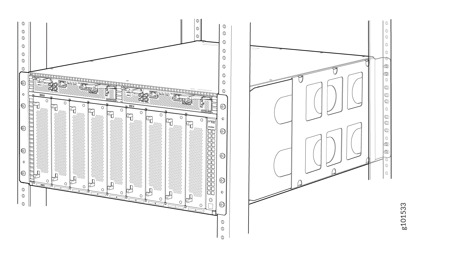
Here’s how to install the ACX7509 in a four-post rack:

  1. Review the General Safety Guidelines and Warnings.
  2. Wrap and fasten one end of the ESD grounding strap around your bare wrist, and connect the other end to a site ESD point.
  3. Decide which end of the router you want to place at the front of the rack. Position the router so that the AIR OUT labels are facing the hot aisle.
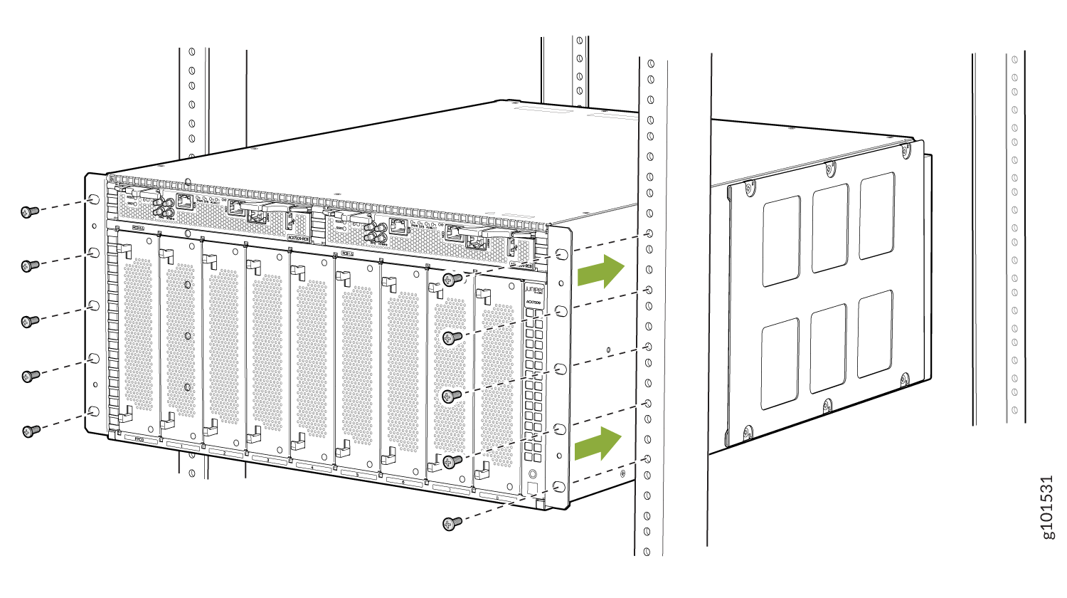
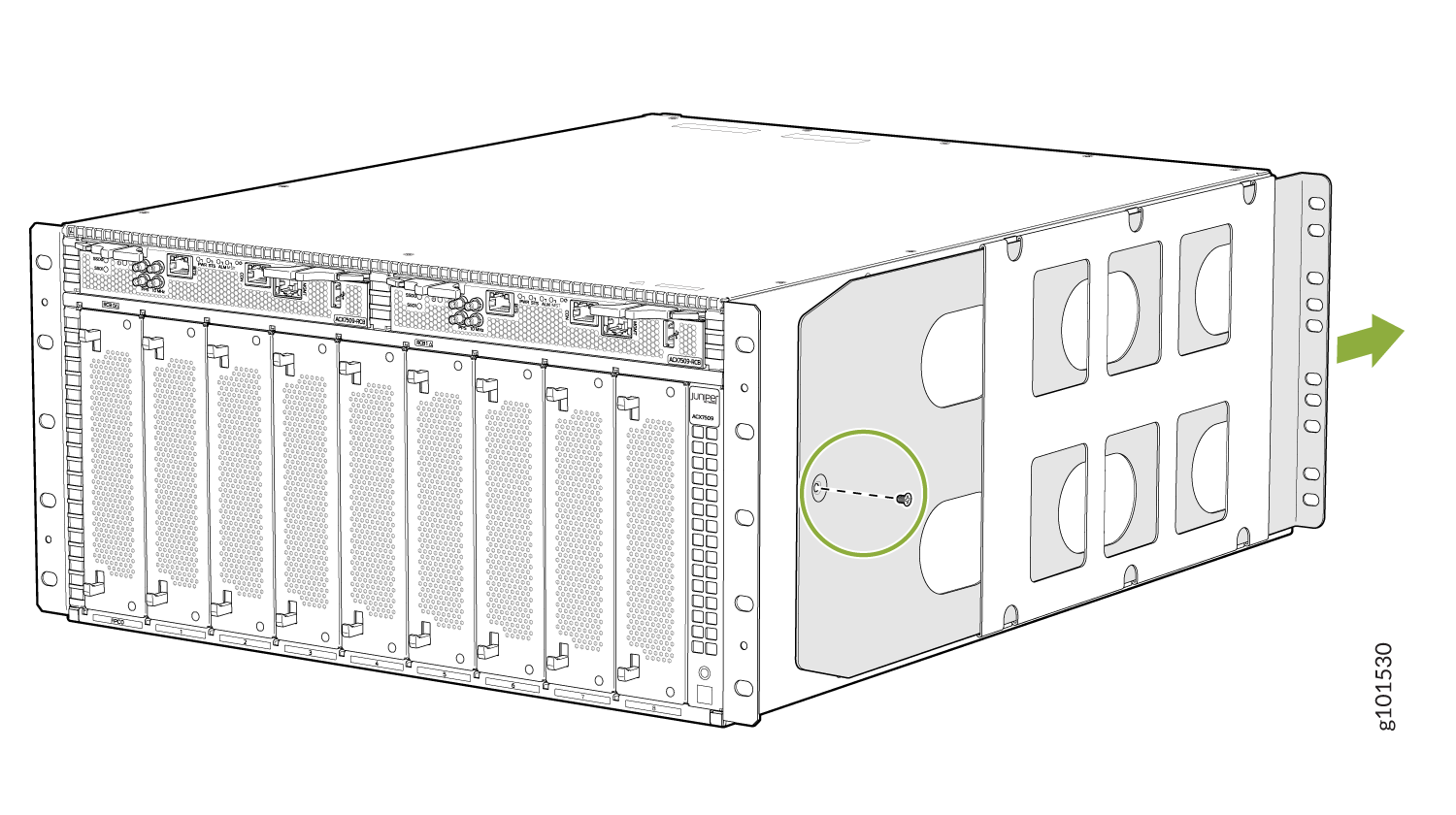
  4. Using a Phillips screwdriver, remove the screws on each side of the chassis that holds the rear mounting-blades to the chassis.
  5. Slide the mounting blades out of the channels.
  6. Perform one of the following steps:
    • Use a mechanical lift to position the ACX7509 in the rack so that the chassis flanges contact the rack rails and the flange’s holes are aligned with the rack holes.

    • With one person on each side and the third person to support the rear, hold on to the bottom of the chassis, and carefully lift the chassis and position it in the rack so that the chassis flanges contact the rack rails and the flange’s holes are aligned with the rack holes.

  7. Continue to support the ACX7509 in place. Starting at the bottom, attach the chassis to the rack by installing mounting screws through the flange and rack hole. Tighten the screws with the Phillips screwdriver.
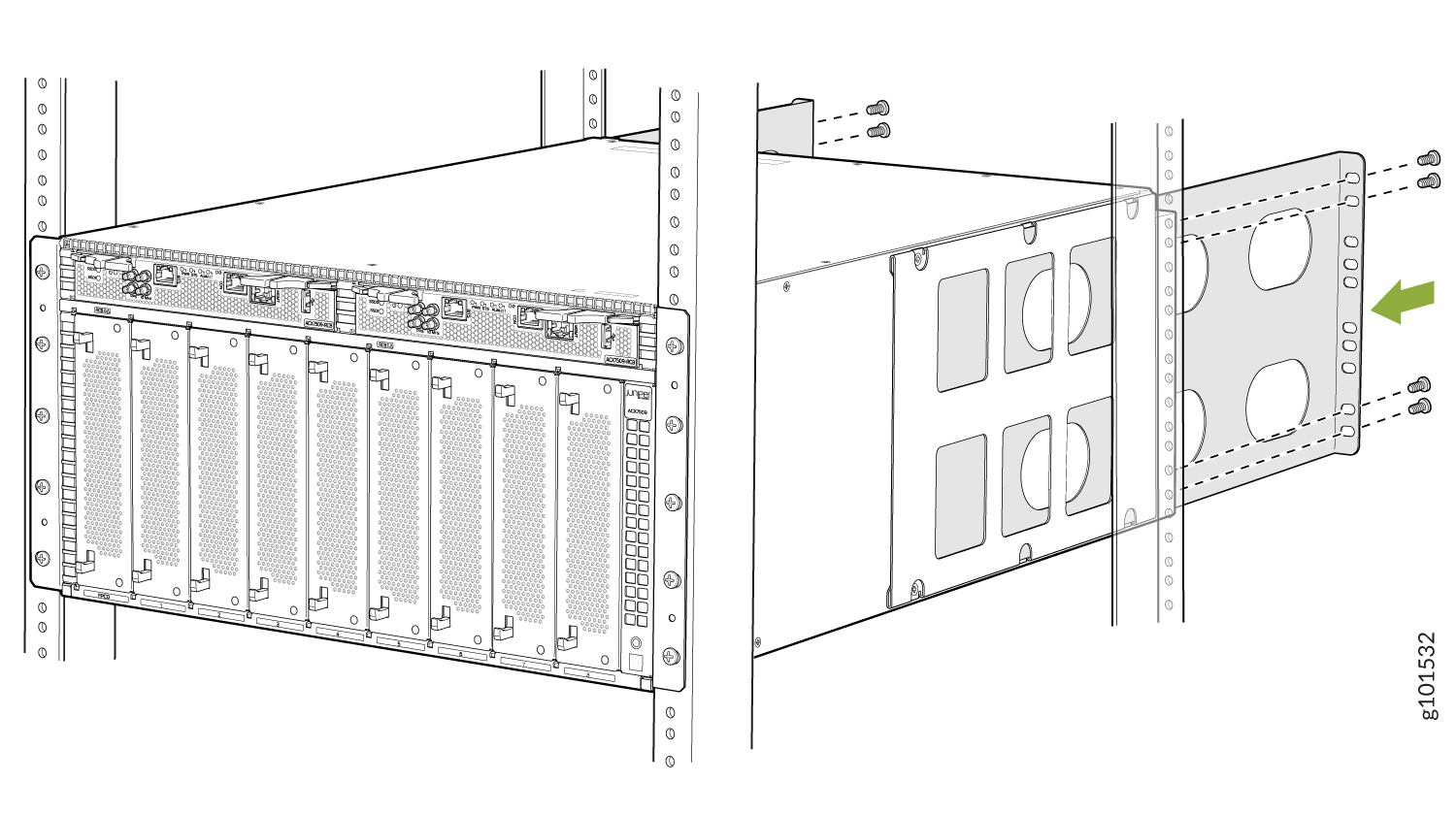
  8. Continue holding the router in place. Slide the mounting blades into the channels on either side of the chassis.
  9. Secure the mounting blades to the rack rails using the rack mount screws (and cage nuts and washers, if your rack requires them).
  10. Visually inspect the alignment of the chassis. Make sure the router is level and the mounting screws on each side of the rack are aligned.

    If you’ve installed the chassis properly in the rack, all the mounting screws on one side of the rack are aligned with the mounting screws on the opposite side, and the router is level.

    Note:

    If you have unused ports, plug them using dust covers to prevent dust from entering the router.

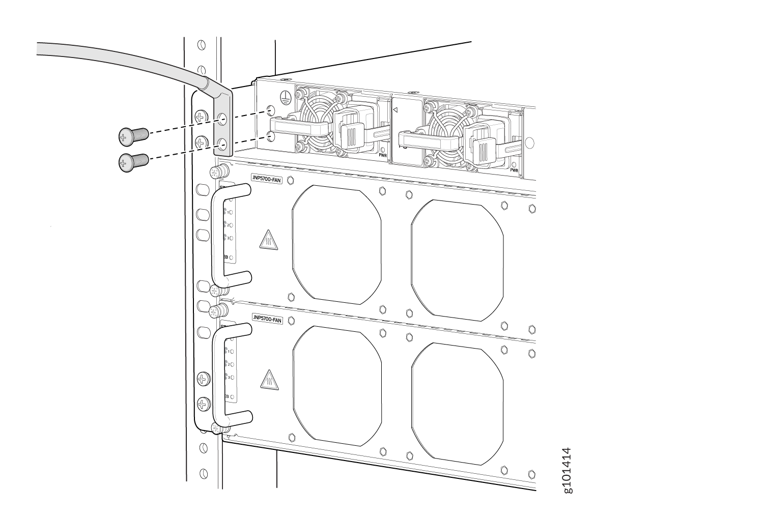
  11. Remove the M6 pan head screws from the chassis and secure the grounding lug and attached cable to the chassis with the M6 pan head screws. The earthing terminal is on the rear side of the chassis.
  12. Connect the other end of the grounding cable to a proper earth ground, such as the rack.
  13. Dress the grounding cable. Ensure that it doesn’t touch or block access to other device components, and that it doesn’t drape where people could trip over it.

Power On

Now that you’ve installed your ACX7509 in the rack and grounded the chassis, you’re ready to connect it to power.

The ACX7509 router supports redundant AC/HDVC or DC power supplies that are pre-installed at the factory. In this guide, we show you how to connect AC power for AC power installations. See the ACX7509 Router Hardware Guide for information on DC power installation.

The AC-powered ACX7509 router comes with four AC power supplies preinstalled on the rear of the device.

  1. Wrap and fasten one end of the ESD grounding strap around your bare wrist, and connect the other end to one of the ESD grounding points on the router.
  2. Ensure that the power supplies are fully inserted in the chassis and the latches are secure.
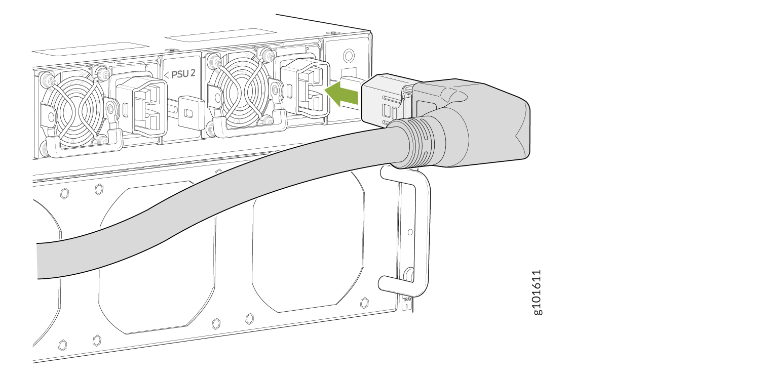
  3. Plug the power cords into the power sockets of each AC power supply.
  4. If the AC power outlet has a power switch, turn it off.
    Note:

    The router powers on as soon as you connect it to power. The ACX7509 doesn't have a power switch.

  5. Plug in each power cord to an AC power outlet.
    Warning:

    Ensure that the power cord does not block access to router components or drape where people can trip on it.

  6. If the AC power outlet has a power switch, turn it on.
  7. Verify that the AC LED on the power supply is lit green. If the LED is lit steadily amber or is blinking amber, disconnect the power supply from the power source, and replace the power supply (see Maintain the ACX7509 Power Supplies in the ACX7509 Router Hardware Guide). Do not remove the power supply until you have a replacement power supply ready.