Help us improve your experience.

Let us know what you think.

Do you have time for a two-minute survey?


Step 6: Connect Power Cables

Depending on its configuration, the firewall uses either AC or DC power supplies. Perform the appropriate procedures for each power supply in the firewall.

Connect Power to an AC-Powered Firewall

This procedure addresses connecting power to firewalls equipped with either standard-capacity or high-capacity AC power supplies.

Warning:

To meet safety and electromagnetic interference (EMI) requirements and to ensure proper operation, you must properly ground the firewall chassis before connecting power. See Step 4: Connect the Grounding Cable for instructions.

Note:

The firewall must be running Junos OS Release 10.4 or later in order to use high-capacity AC power supplies.

Note:

The device is not shipped with AC power cords. Make sure to order or obtain AC power cords with a plug appropriate for your geographical location.

  1. Locate the power cords you will use to connect the device to AC power. See the SRX5800 Firewall Hardware Documentation at www.juniper.net/documentation/ for specifications.
  2. Attach an electrostatic discharge (ESD) grounding strap to your bare wrist, and connect the strap to one of the ESD points on the chassis. For more information about ESD, see the SRX5800 Firewall Hardware Documentation at www.juniper.net/documentation/.
  3. For high-capacity AC power supplies, check the setting of the input mode switch:
    1. Move or remove the metal plate that covers the input mode switch. On some power supply versions, the cover pivots at one end, and you can simply swing it up out of the way. On other versions, the cover is secured with two captive screws that you must loosen.
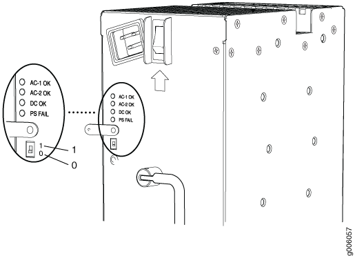
    2. Use a sharp, nonconductive object to slide the switch to the desired position. Move the input mode switch on each power supply to position 0 for one feed or position 1 for two feeds (see Figure 1). We recommend that you use two AC power feeds and set the mode input switch to 1.
      Figure 1: High-Capacity AC Power Supply Input Mode SwitchHigh-Capacity AC Power Supply Input Mode Switch
      Note:

      Do not use a pencil to set the mode switch, because fragments can break off and cause damage to the power supply.

    3. Restore the metal plate to its original position over the input mode switch.
  4. For each power supply:
    1. Move the power switch above the power supply to the OFF position (O). For high-capacity AC power supplies, also move the switch on the power supply itself to the OFF position (O).
    2. Insert the appliance coupler end of a power cord into the appliance inlet above the power supply. For high-capacity power supplies, also insert the appliance coupler end of a power cord into the appliance inlet on the power supply itself.
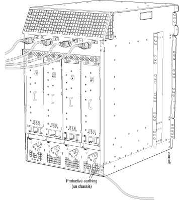
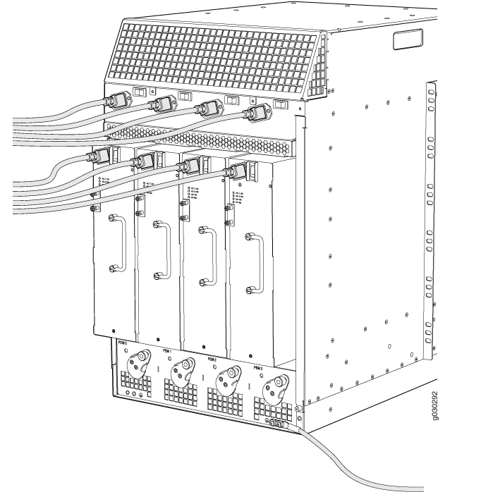
    3. Insert each power cord plug into an external AC power source receptacle (Figure 2 and Figure 3.
      Note:

      Each power supply must be connected to a dedicated AC power feed and a dedicated customer site circuit breaker. We recommend using a 15-A (250-VAC), circuit breaker minimum, or as permitted by local code.

      Figure 2: Connecting AC Power to the Firewall (Standard-Capacity AC Power Supplies)Connecting AC Power to the Firewall (Standard-Capacity AC Power Supplies)
      Figure 3: Connecting AC Power to the Firewall (High-Capacity Power Supplies )Connecting AC Power to the Firewall (High-Capacity Power Supplies )
    4. Dress each power cord appropriately. Verify that the power cord does not block the air exhaust or access to firewall components, and that it does not drape where people could trip over it.

Connect Power to a DC-Powered Firewall

Warning:

To meet safety and electromagnetic interference (EMI) requirements and to ensure proper operation, you must properly ground the firewall chassis before connecting power. See Step 4: Connect the Grounding Cable for instructions.

Table 1 describes the firewall input voltage requirements.

Table 1: SRX5800 Firewall DC Power System Input Voltage

Item

Specification

DC input voltage

Operating range: –40 to –72 VDC

  1. Ensure that the voltage across the DC power source cable leads is 0 V and that there is no chance that the cable leads might become active during installation.
  2. For high-capacity DC power supplies, check the setting of the input mode switch:
    1. Move or remove the metal plate that covers the input mode switch. On some power supply versions, the cover pivots at one end, and you can simply swing it up out of the way. On other versions, the cover is secured with two captive screws that you must loosen.
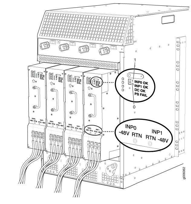
    2. Use a sharp, nonconductive object to slide the switch to the desired position. Move the input mode switch on each power supply to position 0 for one feed or position 1 for two feeds (see Figure 4). We recommend that you use two DC power feeds and set the mode input switch to 1.
      Note:

      Do not use a pencil to set the mode switch, because fragments can break off and cause damage to the power supply.

    3. Restore the metal plate to its original position over the input mode switch.
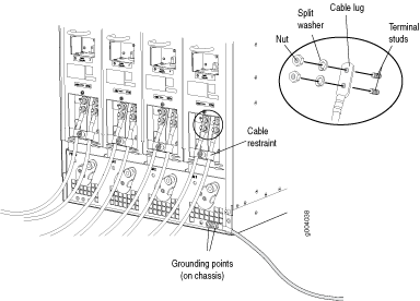
  3. For standard-capacity DC power supplies, secure the power cable lugs to the terminal studs, first with the split washers, then with the nuts as shown in Figure 4. Apply between 23 lb-in. (2.6 Nm) and 25 lb-in. (2.8 Nm) of torque to each nut. Do not overtighten the nut. (Use a 7/16-in. torque-controlled driver or socket wrench.)
    1. Attach the positive (+) DC source power cable lug to the RTN (return) terminal.
    2. Attach the negative (–) DC source power cable lug to the –48V (input) terminal.
    3. Loosen the captive screw on the cable restraint on the lower edge of the power supply faceplate.
    4. Engage the DC power cables with the cable restraint, and tighten the captive screw.
    Figure 4: Connecting Power Cables (Standard-Capacity DC Power Supplies)Connecting Power Cables (Standard-Capacity DC Power Supplies)
    CAUTION:

    Ensure that each power cable lug seats flush against the surface of the terminal block as you are tightening the nuts. Ensure that each nut is properly threaded onto the terminal stud. The nut should be able to spin freely with your fingers when it is first placed onto the terminal stud. Applying installation torque to the nut when it is improperly threaded might result in damage to the terminal stud.

    CAUTION:

    The maximum torque rating of the terminal studs on the DC power supply is 58 lb-in. (6.5 Nm). The terminal studs might be damaged if excessive torque is applied. Use only a torque-controlled driver or socket wrench to tighten nuts on the DC power supply terminal studs.

    Note:

    For information about connecting to external DC power sources, see the SRX5800 Firewall Hardware Documentation at www.juniper.net/documentation/.

  4. For high-capacity DC power supplies, secure the power cable lugs to the terminal studs, first with the split washers, then with the nuts as shown in Figure 5. Apply between 23 lb-in. (2.6 Nm) and 25 lb-in. (2.8 Nm) of torque to each nut. Do not overtighten the nut. (Use a 7/16-in. torque-controlled driver or socket wrench.)
    1. Attach the positive (+) DC source power cable lugs to the RTN (return) terminals for the INP0 and INP1 connector pairs.
    2. Attach the negative (–) DC source power cable lug to the –48V (input) terminals for the INP0 and INP1 connector pairs.
    Figure 5: Input Mode Switch and Power Cable Connectors (High-Capacity DC Power Supplies)Input Mode Switch and Power Cable Connectors (High-Capacity DC Power Supplies)
    CAUTION:

    Ensure that each power cable lug seats flush against the surface of the terminal block as you are tightening the nuts. Ensure that each nut is properly threaded onto the terminal stud. The nut should be able to spin freely with your fingers when it is first placed onto the terminal stud. Applying installation torque to the nut when improperly threaded might result in damage to the terminal stud.

    CAUTION:

    The maximum torque rating of the terminal studs on the DC power supply is 58 lb-in. (6.5 Nm). The terminal studs might be damaged if excessive torque is applied. Use only a torque-controlled driver or socket wrench to tighten nuts on the DC power supply terminal studs.

    Note:

    For information about connecting to DC power sources, see the SRX5800 Firewall Hardware Documentation at www.juniper.net/documentation/.

  5. Connect each DC power cable to the appropriate external DC power source.
    Note:

    For information about connecting to external DC power sources, see the SRX5800 Firewall Hardware Documentation at www.juniper.net/documentation/.

  6. Switch on the external circuit breakers to provide voltage to the DC power source cable leads.