SRX1600 Power System
The SRX1600 is powered by two power supplies for 1 + 1 redundancy. The SRX1600 has hot-removable and hot-insertable power supply units (PSUs). If one PSU fails, you can replace it without powering off or disrupting the device function. The second PSU balances the electrical load without interruption. A fan in each power supply provides cooling.
We ship the SRX1600 with only one PSU. You can order the second PSU separately if required.
You must not mix AC and DC power supplies in the same chassis.
AC Power Supply for SRX1600 Firewalls
The following figure shows the AC PSU.
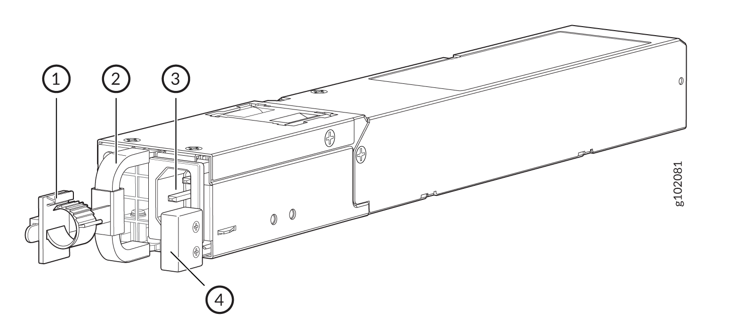
| Callout | Name |
|---|---|
| 1 | Power cord retainer |
| 2 | PSU handle |
| 3 | AC power inlet |
| 4 | PSU latch |
| Height | Width | Depth (including handle) | Weight |
|---|---|---|---|
|
1.61 in. (4.1 cm) |
2.17 in. (5.5 cm) |
14.17 in. (36 cm) |
2.14 lb (970 g) |
Table 3 describes the AC power specifications for SRX1600.
| Item | Specification |
|---|---|
| AC input voltage | Operating range: 100–127 VAC / 200–240 VAC |
| AC input line frequency | 50–60 Hz |
| AC input current rating |
5.5 A at 100–127 VAC 3 A at 200–240 VAC |
| Maximum power output | 450 W |
| Item | Specification |
|---|---|
| Maximum power consumption | 162 W |
| Average power consumption |
137 W |
You must use a dedicated external circuit breaker for each PSU. We recommend that you use a 10 A (250 VAC), or as permitted by the local code.
Supported AC Power Cords
Use the AC power cord with the firewall only and not for any other purpose.
In North America, AC power cords must not exceed a length of 4.5 m (approximately 14.75 ft). This length complies with National Electrical code (NEC) Section 400-8 (NFPA 75, 5-2.2) and 210-52, and Canadian Electrical Code (CEC) Section 4-010(3).
Table 3 provides power cord specifications, and Figure 2depicts the plug on the AC power cord provided for each country or region.
| Country | Electrical Specification | Plug Standards |
|---|---|---|
|
Australia |
250 VAC, 10 A, 50 Hz |
AS/NZ 3112-1993 |
|
China |
250 VAC, 10 A, 50 Hz |
GB2099.1 1996 and GB1002 1996 (CH1-10P) |
|
Europe (except Italy and United Kingdom) |
250 VAC, 10 A, 50 Hz |
CEE (7) VII |
|
Italy |
250 VAC, 10 A, 50 Hz |
CEI 23-16/VII |
|
Japan |
125 VAC, 12 A, 50 or 60 Hz |
JIS 8303 |
|
North America |
125 VAC, 10 A, 60 Hz |
NEMA 5-15 |
|
United Kingdom |
250 VAC, 10 A, 50 Hz |
BS 1363A |
Power cords and cables must not block access to firewall components or drape where people might trip on the cables.
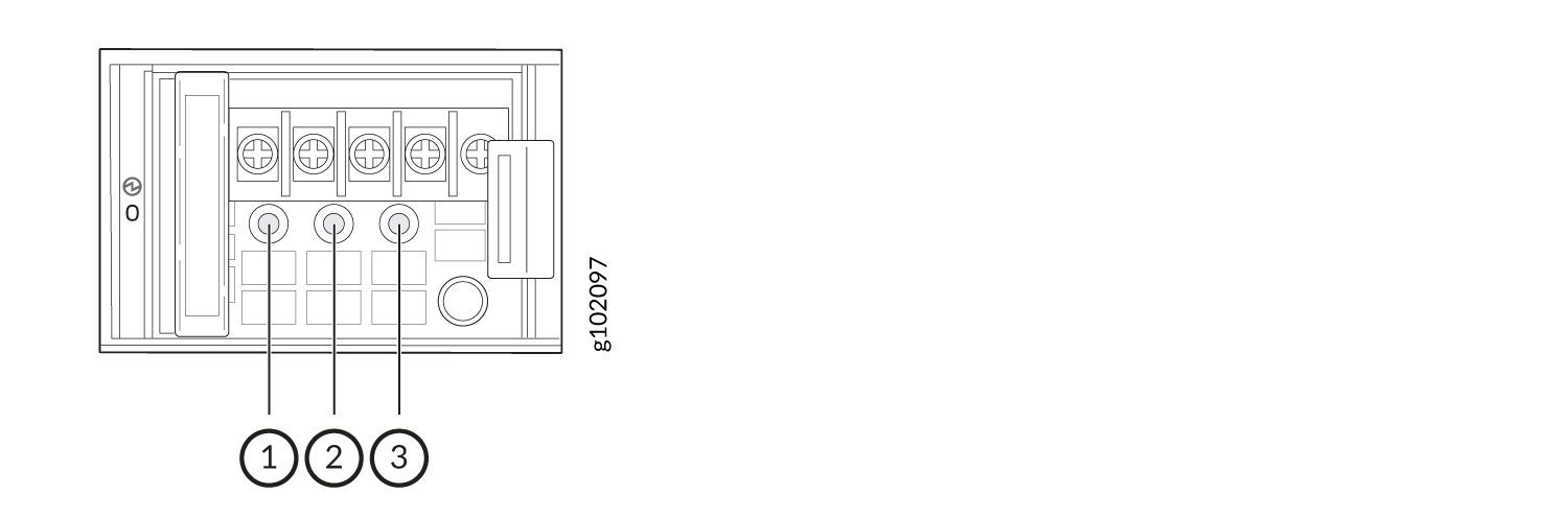
DC Power Supply for SRX1600 Firewalls
The following figure shows the DC PSU.
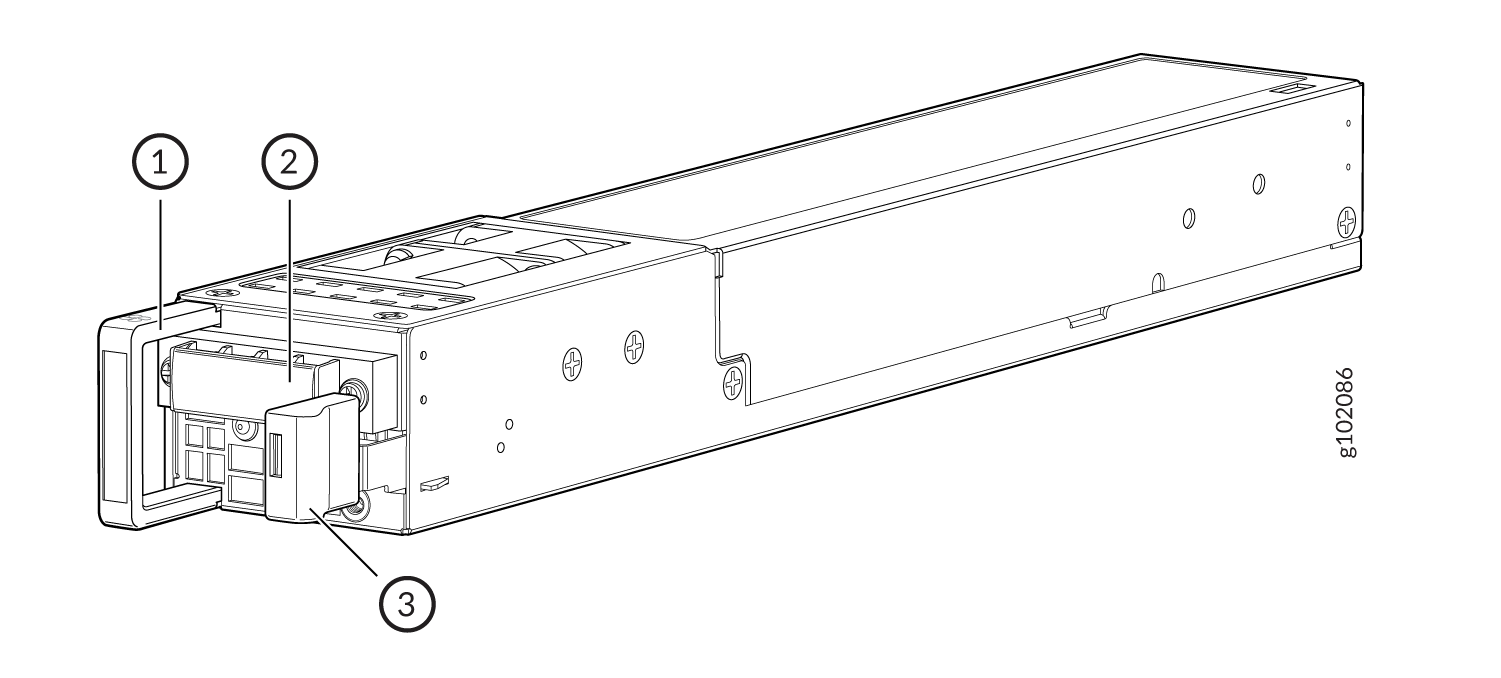
| Callout | Name |
|---|---|
| 1 | PSU handle |
| 2 | DC power terminals |
| 3 | PSU latch |
| Height | Width | Depth | Weight |
|---|---|---|---|
|
1.61 in. (4.1 cm) |
2.17 in. (5.5 cm) |
14.17 in. (36 cm) (including handle) |
2.16 lb (980 g) |
DC Power Specifications for SRX1600 describes the DC power specifications for SRX1600.
| Item | Specification |
|---|---|
| DC Input Voltage | –44 VDC through –72 VDC |
| DC input current rating | 20 A maximum |
| Maximum power output | 650 W |
| Item | Specification |
|---|---|
| Maximum power consumption | 161 W |
| Average power consumption |
132 W |
PSU LEDs on SRX1600 Firewalls
The AC PSU has a single bicolor LED that indicates the status.Figure 4 shows the location of the LED on the AC PSU and Table 10 describes it.
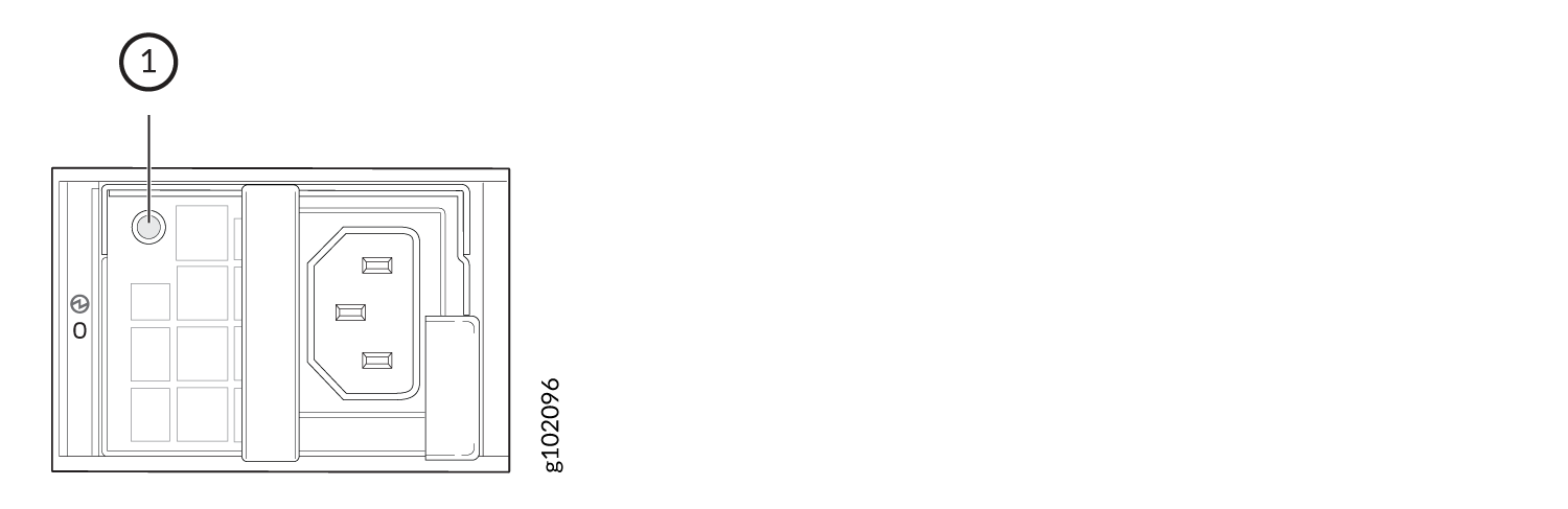
| Callout | Color | State | Description |
|---|---|---|---|
| 1 | Unlit | Off | No power input. |
| Green | On | PSU is operating normally. | |
| Blinking | The device is in standby mode. | ||
| Amber | Blinking | PSU is operating under overload. | |
| On | The system has detected an error in the PSU. Replace the PSU immediately. To maintain proper airflow through the chassis, leave the PSU installed in the chassis until you are ready to replace it. |
Figure 5 shows the location of the LEDs on the DC PSU and Table 11 describes the LEDs.
| Callout | Name | Color | State | Description |
|---|---|---|---|---|
| 1 | Input | Unlit | Off | No power input. |
| Green | On | The PSU is operating normally. | ||
| 2 | Output | Unlit | Off | No power output. |
| Green | On | The PSU is operating normally. | ||
| 3 | Fault | Amber | On | The system has detected an error in the PSU. Replace the PSU immediately. To maintain proper airflow through the chassis, leave the PSU installed in the chassis until you are ready to replace it. |