SSR130 Chassis
Front Panel of an SSR130
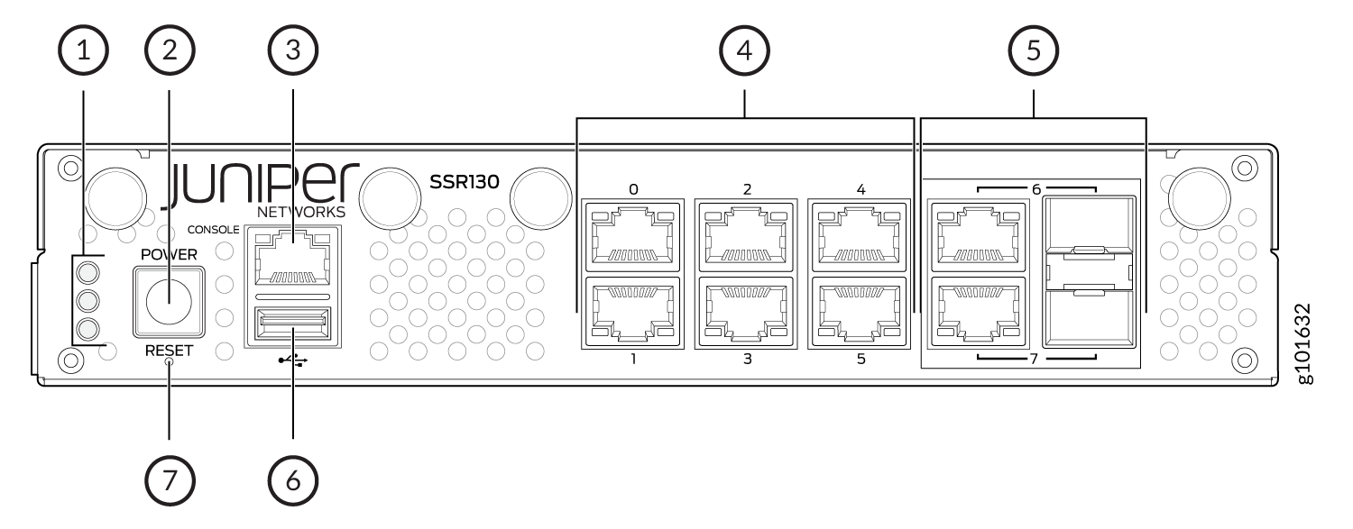
Figure 1 shows the front panel of an SSR130.

1 — Chassis LEDs | 5 — 1 GbE RJ-45/SFP combo ports |
2 — Power button | 6 — USB 3.0 port |
3 — Console Port | 7 — Reset button |
4 — 1 GbE Ethernet ports |
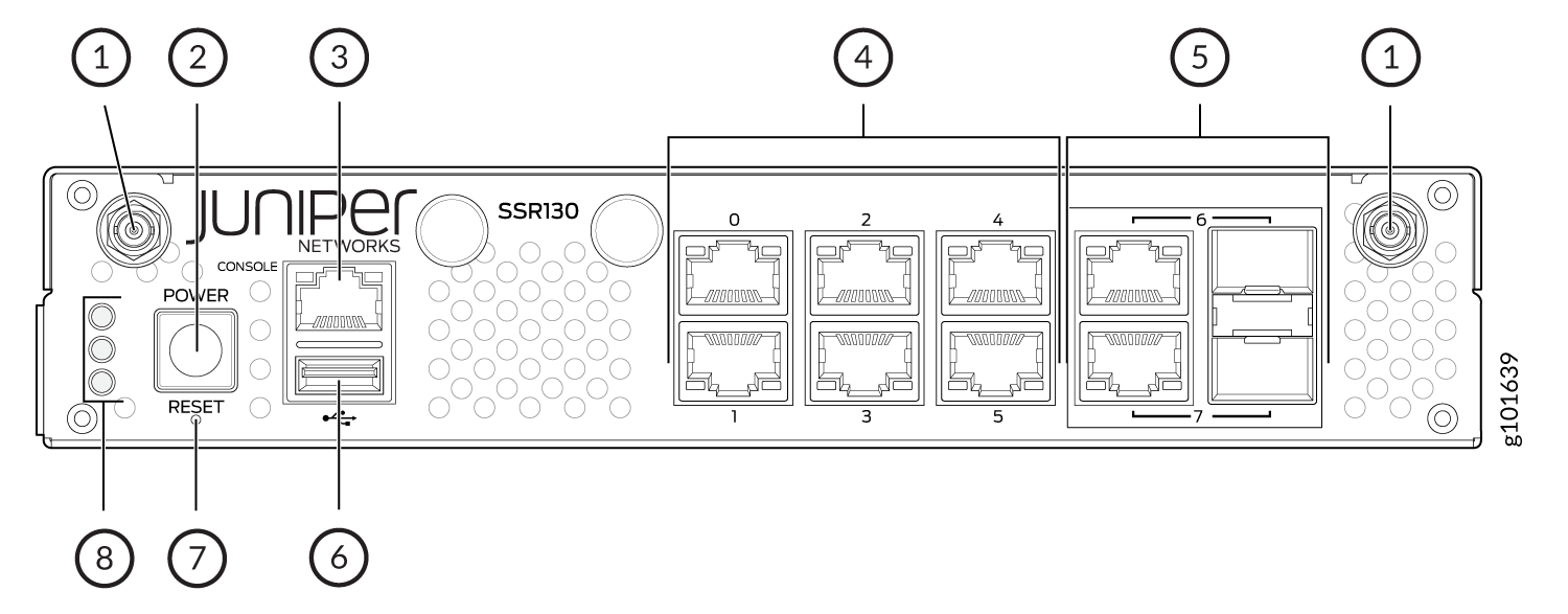
Figure 2 shows the front panel components of SSR130-AA and SSR130-AE.

1 — Antenna connectors | 5 — 1 GbE RJ-45/SFP Combo Ports |
2 — Power button | 6 — USB 3.0 port |
3 — Console Port | 7 — Reset button |
4 — 1 GbE Ethernet Ports | 8 — Chassis LEDs |
The SSR130 supports two 1 GbE RJ-45/SFP combo ports for WAN connectivity. You can connect either an SFP (fiber) or RJ-45 (copper) cable on the 1 GbE RJ-45/SFP combo port. The SSR130 automatically detects the media that is connected on the combo port.
If you connect both copper and fiber cables, then the media that establishes the link first becomes active and the other media is automatically disabled to save power. If the link goes down, then the disabled media is powered up and both media tries to establish the link again.
Rear Panel of an SSR130
Figure 3 shows the rear panel of an SSR130.

1 — Ground terminal | 3 — Redundant power input (do not use) |
2 — Fans | 4 — Main power input |
The SSR130 does not support the following:
PoE power input
Redundant power input
Chassis Status LEDs
The SSR130 has three LEDs on the front panel to indicate the status.

Table 1 describes the chassis status LEDs on SSR130, their colors and states, and the status that they indicate.
Status |
LED State and Color |
|---|---|
OS boot process is complete |
LED 1—On, Blue LED 2—Off, Unlit LED 3—On, Blue |
Device is powered off by the OS |
LED 1—On, Amber LED 2—Off, Unlit LED 3—On, Blue |
Network Port LEDs
Each network port has two LEDs to indicate the link activity and status of the port.

1 — Link (Ethernet port) | 3 — Link (RJ-45/SFP combo port) |
2 — Activity (Ethernet port) | 4 — Activity (RJ-45/SFP combo port) |
Table 2 and Table 3 describe the Link and Activity LEDs on the network ports.
|
LED |
Color |
State |
Description |
|---|---|---|---|
|
Link |
Orange |
On steadily |
1-Gbps link is established. |
|
Unlit |
Off |
10-Mbps or 100-Mbps link is established if the Activity LED is also lit green. However, if the Link LED and Activity LED are both unlit, it indicates that there is no link established. |
|
|
Activity |
Green |
Blinking |
The link is up and there is traffic on the port. |
|
Green |
On steadily |
The link is up but there is no traffic on the port. |
|
|
Unlit |
Off |
The link is down. |
|
LED |
Color |
State |
Description |
|---|---|---|---|
|
Link |
Orange |
On steadily |
10-Mbps or 100-Mbps link is established. |
|
Orange |
Blinking |
10-Mbps or 100-Mbps link is established and there is traffic on the port |
|
| Unlit | Off |
1-Gbps link is established if the Activity LED is also lit green. However, if the Link LED and Activity LED are both unlit, it indicates that there is no link established. |
|
|
Activity |
Green |
Blinking |
100-Mbps or 1-Gbps link is established and there is traffic on the port. |
|
Green |
On steadily |
100-Mbps or 1-Gbps link is established, but there is no traffic on the port. |
|
|
Unlit |
Off |
10-Mbps link is established if the Link LED is also lit orange. However, if the Link LED and Activity LED are both unlit, it indicates that there is no link established. |
SSR130 Power System
The SSR130 uses an external AC to DC power adapter.
Table 4 lists the specifications for the power supply adapter.
Model |
Power Adapter Input (AC) |
Power Adapter Output (DC) |
Maximum Power Consumption |
|---|---|---|---|
SSR130 |
100-240V AC, 50-60 Hz, 2 A |
12V DC, 5 A |
41.5 W |
SSR130-AA |
100-240V AC, 50-60 Hz, 2 A |
12V DC, 5 A |
41.5 W |
SSR130-AE |
100-240V AC, 50-60 Hz, 2 A |
12V DC, 5 A |
41.5 W |
The SSR130 does not support a redundant power adapter.
Cooling System
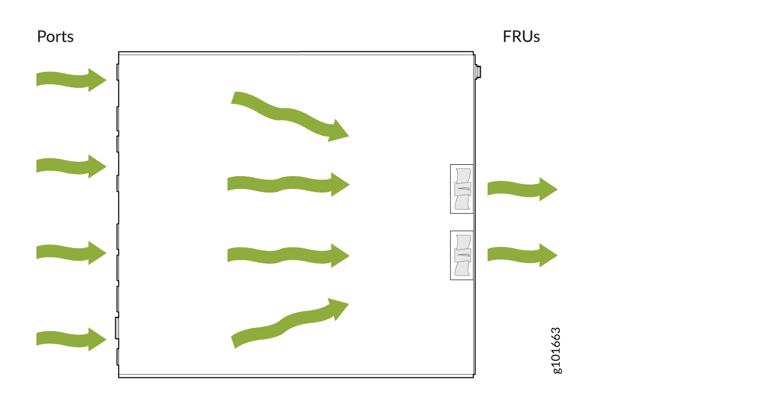
The cooling system of the SSR130 consists of two fans. The fan controller monitors the temperature of the chassis and adjusts the fan speed according to the temperature. The SSR130 appliances have front-to-back airflow. See Figure 6.

