Unpack and Mount an SSR130
Unpack an SSR130
The SSR130 is shipped in a cardboard carton and secured with foam packing material. The carton also contains an accessory box and quick start instructions.
The SSR130 is maximally protected inside the cardboard carton. Do not unpack it until you are ready to begin installation.
To unpack the SSR130:
- Move the cardboard carton to a staging area as close to the installation site as possible, where you have enough room to remove the components from the chassis.
- Position the cardboard carton with the arrows pointing up.
- Carefully open the top of the cardboard carton.
- Remove the foam covering the top of the SSR130.
- Remove the accessory box.
- Verify the parts received against the lists in Table 1.
- Store the brackets and bolts inside the accessory box.
- Save the shipping carton and packing materials in case you need to move or ship the services gateway at a later time.
Verify Parts Received with the SSR130
The shipment includes a packing list. Check the parts you receive in the shipping carton against the items on the packing list. The parts shipped depend on the configuration you order.
If any part on the packing list is missing, contact your customer service representative or contact Juniper customer care from within the U.S. or Canada by telephone at 1-888-314-5822. For international-dial or direct-dial options in countries without toll-free numbers, see https://www.juniper.net/support/requesting-support.html.
Component |
Quantity |
|---|---|
SSR130 Chassis |
1 |
DB-9 to RJ-45 adapter, straight through cable |
1 |
C13 power cord appropriate for your geographical location |
1 |
AC/DC power adapter |
1 |
LTE antennas (provided for SSR130-AA and SSR130-AE models) |
2 |
Rack mount kit (separately orderable)Part Number: SSR100-RMK |
|
Documentation Roadmap and Product Warranty |
1 |
Update Base Installation Data
Update the installation base data if any addition or change to the installation base occurs or if the installation base is moved. Juniper Networks is not responsible for not meeting the hardware replacement SLA for products that do not have accurate installation base data.
Update your installation base at https://supportportal.juniper.net/s/CreateCase .
Mount an SSR130 on a Desk or Other Level Surface
Before mounting SSR130 on a desk or other level surface:
Verify that the site meets the requirements described in SSR130 Site Guidelines and Requirements.
Place the desk in its permanent location, allowing adequate clearance for airflow and maintenance, and secure it to the building structure.
Read General Safety Guidelines and Warnings, with particular attention to Chassis and Component Lifting Guidelines.
Do not block the vents on the enclosure of the SSR130 chassis. Blocking the vents can lead to overheating of the appliance.
To mount an SSR130 on a desk or other level surface:
Remove the appliance from the shipping carton (see Unpack an SSR130).
Place the SSR130 on the desk or the level surface.
Ensure that SSR130 rests firmly on the desk or level surface.
Mount an SSR130 on a Two-Post Rack
If you need to mount an SSR130 on a two-post rack you must order the rack-mount kit (SSR100-RMK).
Before mounting an SSR130 on a two-post rack:
Verify that the site meets the requirements described in SSR130 Site Guidelines and Requirements.
Place the rack in its permanent location, allowing adequate clearance for airflow and maintenance, and secure it to the building structure.
Read General Safety Guidelines and Warnings, with particular attention to Chassis and Component Lifting Guidelines.
Ensure that you have the following parts and tools available:
Separately oderable rack mount kit (SSR100-RMK)
2 Mounting Brackets
4 M5x7.0mm flat-head bracket screws
4 flat-head M6x16mm Phillips round head mounting screws
4 M6 Floating nut in cage, steel+zinc
4 M6 plastic washers
Phillips (+) screwdriver, number 2
One person must be available to lift the SSR130 chassis while another secures the chassis to the rack.
If you are mounting multiple units on a rack, mount the heaviest unit at the bottom of the rack and mount the other units from the bottom of the rack to the top in decreasing order of the weight of the units.
To mount the SSR130 on a two-post rack:
- Align the mounting brackets along the front of the appliance
such that the holes in the mounting brackets align with the holes
on the side panels of the appliance. See Figure 1.Figure 1: Attaching the Mounting Brackets

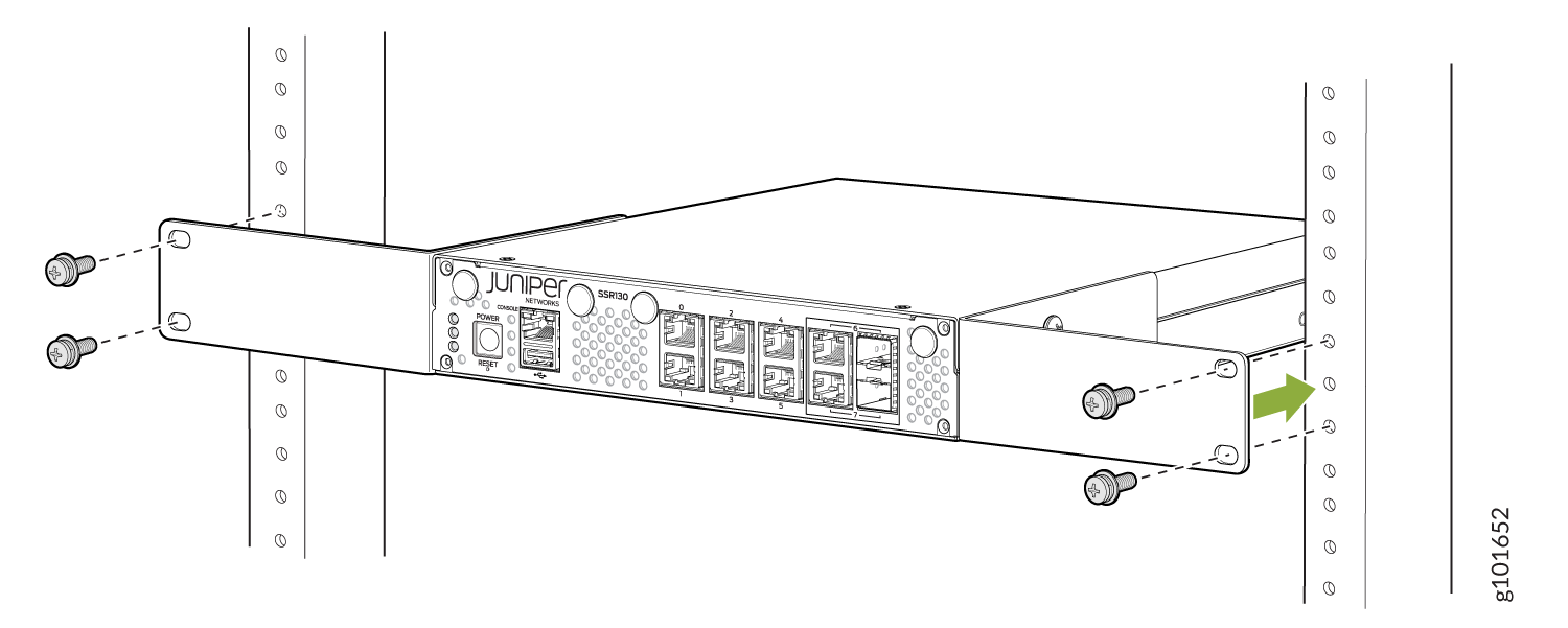
- Have one person grasp both sides of the appliance, lift
the appliance, and position it in the rack, aligning the mounting
bracket holes with the threaded holes in the rack rail. Align the
bottom hole in each mounting bracket with a hole in each rack rail,
making sure the appliance is level. See Figure 2.Figure 2: Mounting the SSR130 on a Two-Post Rack
Installing Antennas for the SSR130 Appliances that Support LTE
To install the antennas:
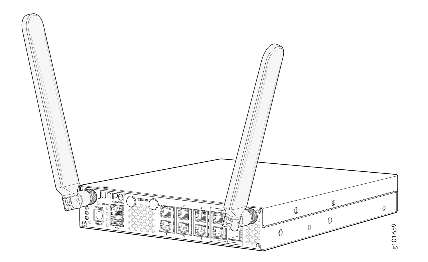
Remove the dust caps from the SMA connectors from the SSR130 front panel.
Attach the antennas to the SMA connectors and tighten them firmly by hand.
Figure 3: Attaching Antennas to SSR130
Rotate the antennas 0-90 degree in the vertical direction.
Inserting the SIM Card
The SSR130 LTE Variants (SSR130-AA and SSR130-AE) support Micro-SIM card.
To insert a Micro-SIM card:
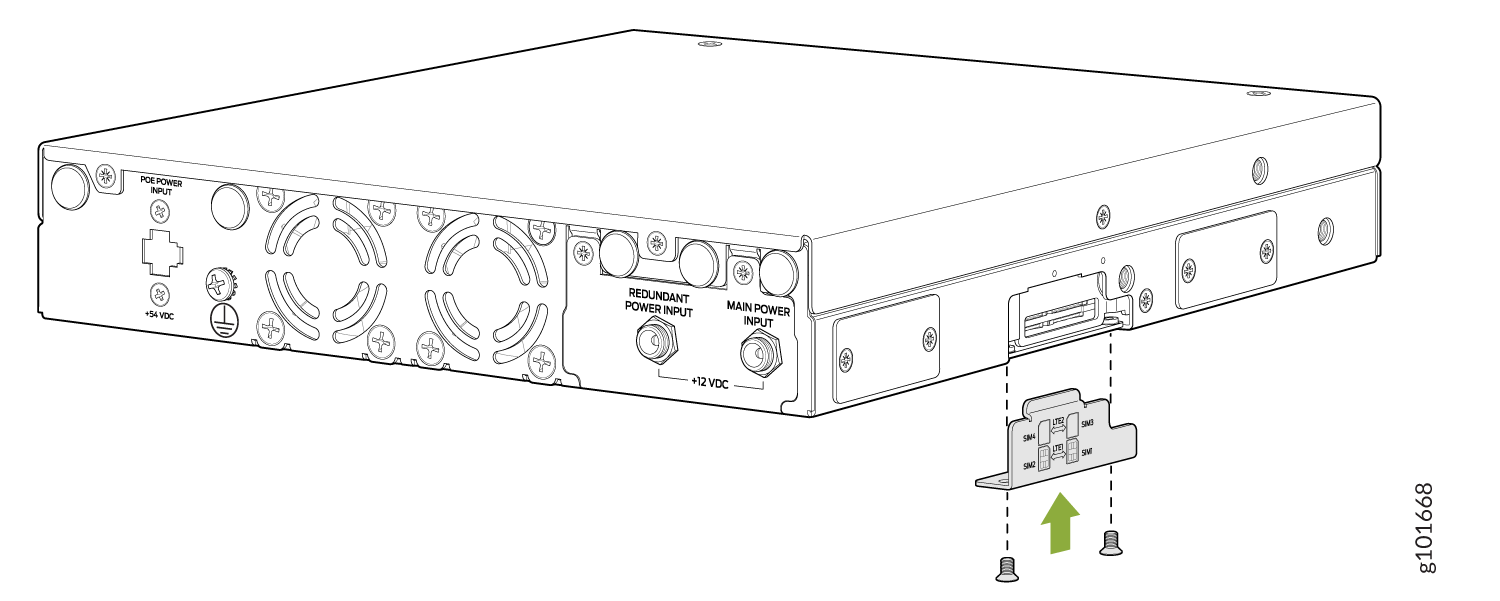
Using a Philips screwdriver remove the SIM card slot cover on the side of the appliance. See Figure 4.
Figure 4: Removing the SIM Card Slot Cover
-
Insert the Micro-SIM card in slot SIM1.
Figure 5: Inserting the Micro-SIM Card Note:
Note:You can insert the Micro-SIM card only in the SIM1 slot, not in the other SIM slots. When you insert the Micro-SIM card, make sure to orient the card correctly.
Replace the SIM card slot cover and tighten its screws with a torque of 6 Nm.
Figure 6: Replacing the SIM Card Slot Cover