Connect SSR1400 to Power
Connecting power to the SSR1400 appliance involves numerous steps and safety precautions to prevent equipment damage and personal injury.
To meet safety and electromagnetic interference (EMI) requirements and to ensure proper operation, you must connect the SSR1400 appliance to an earth ground before you connect it to power.
Connect Earth Ground to the SSR1400
Before you connect power to the SSR1400, a licensed electrician must attach a cable lug to the grounding and power cables that you supply. A cable with an incorrectly attached lug can damage the services gateway (for example, by causing a short circuit).
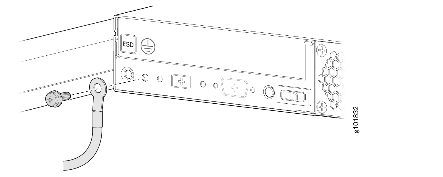
To ground the SSR1400, connect a grounding cable to earth ground. Attach the grounding cable to the chassis grounding point located on the rear of the appliance.
Under all circumstances, use this grounding connection to ground the chassis. For AC-powered systems, you must also use the grounding wire in the AC power cord along with the one-hole grounding ring terminal connection. This tested system meets or exceeds all applicable EMC regulatory requirements with the one-hole protective grounding ring terminal.
You must provide the following items:
-
Grounding cable: The grounding cable must be at least 14 AWG (1.5 mm²) stranded wire and be rated 90 °C or per local electrical code.
-
Grounding ring terminal for your grounding cable: This bracket attaches to the to the chassis grounding point located on the rear of the appliance.
-
A Phillips screwdriver to tighten the screw.
-
An electrostatic discharge (ESD) grounding strap.
We recommend that you install heat-shrink tubing insulation around the crimped section of the earthing cable and ring terminal.
To ground the appliance:
-
Secure the grounding cable ring terminal to the grounding point with the M5
pan head screw.
Figure 1: Connect the Grounding Cable to the SSR1400
Connect AC Power to the SSR1400
The AC power supply units (PSUs) in an SSR1400 are hot-removable and hot-insertable field-replaceable units (FRUs). You can remove and replace the PSUs without powering off the appliance or disrupting its functions.
Before you begin to connect AC power to the appliance:
-
Ensure that you have connected the appliance chassis to an earth ground.
CAUTION:Before you connect power to the appliance, a licensed electrician must attach a cable ring terminal to the grounding and power cables that you supply. A cable with an incorrectly attached ring terminal can damage the appliance (for example, by causing a short circuit).
To meet safety and electromagnetic interference (EMI) requirements and to ensure proper operation, you must connect the chassis to an earth ground before you connect it to power. For installations that require a separate grounding conductor to the chassis, use the protective earthing terminal on the appliance chassis to connect to the earth ground. The appliance gains additional grounding when you plug the PSM in the router to a grounded AC power outlet by using the AC power cord appropriate for your geographical location.
-
Ensure that you have a power cord appropriate for your geographical location available to connect AC power to the appliance.
-
Read General Electrical Safety Guidelines and Warnings and Action to Take After an Electrical Accident.
-
Ensure that you have taken the necessary precautions to prevent electrostatic discharge (ESD) damage.
-
Ensure that you have an ESD grounding strap.
-
If not already installed, install the power supplies in the appliance.
To connect AC power to an SSR1400:
-
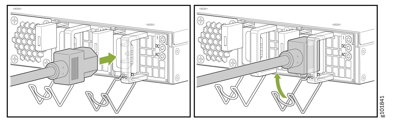
Push the power cord retainer onto the power cord (see Figure 2).
Figure 2: Connect AC Power Cord
Connect DC Power to the SSR1400-DC
Use the following procedure to connect DC power to the SSR1400-DC.
Do not attempt to install a DC power supply into an SSR1400 that originally contained an AC power supply. This may result in damage to the SSR1400, and the appliance may not function.
To meet safety and electromagnetic interference (EMI) requirements and to ensure proper operation, you must properly ground the services gateway chassis before connecting power. See Connect Earth Ground to the SSR1400 for instructions.
Before performing the following procedure, ensure that power is removed from the DC circuit. To ensure that all power is off, locate the circuit breaker on the panel board that services the DC circuit, switch the circuit breaker to the OFF position (0), and tape the switch handle of the circuit breaker in the OFF position. It is recommended to use a non-contact voltage tester to confirm that nothing is energized.
Do not mix AC and DC power supplies within the same SSR device. Damage will occur.
Before you connect power to the SSR device, a licensed electrician must attach appropriate cable lugs to the grounding and power cables. A cable with an incorrectly attached lug can damage the device (for example, by causing a short circuit).
Wire the DC power supply using the appropriate lugs. When connecting power, the proper wiring sequence is:
Ground to Ground
Positive (+) DC source power cable lug to a (+) RTN (return) terminal.
Negative (–) DC source power cable lug to a -48V (input) terminal
When disconnecting power, the proper wiring sequence is:
Negative (–) DC source power cable lug to a -48V (input) terminal
Positive (+) DC source power cable lug to a (+) RTN (return) terminal.
Ground to Ground
Note that the ground wire should always be connected first and disconnected last.
When stranded wiring is required, use approved wiring terminations, such as closed-loop or spade-type with upturned lugs. These terminations should be the appropriate size for the wires and should clamp both the insulation and conductor.
The table below summarizes the specifications for the power cable(s), which you must supply.
|
Cable Type |
Quantity and Specification |
Stud Size |
Ring Connector |
|---|---|---|---|
|
Power |
14-16 AWG, minimum 60° C wire, or as permitted by the local code |
M3 |
Exterior diameter no greater than 5.84mm/.230 inches. |
| Ground | 14 AWG (1.5 mm²) stranded wire rated 90 °C or per local electrical code. |
M5 |
To connect the DC source power cables to each power supply on the SSR1400-DC:
-
If the power cables specified in the table above and prepared by a licensed
electrician do not have heat-shrink tubing insulation around the connection
lugs, use the procedure below to do so:
-
Slide the tubing over the portion of the cable where it is attached to the lug barrel. Ensure that the tubing covers the end of the wire and the barrel of the lug attached to it.
-
Shrink the tubing with a heat gun. Ensure that you heat all sides of the tubing evenly so that it shrinks around the cable tightly.
Note:Do not overheat the tubing.
Figure 3: How to Install Heat-Shrink Tubing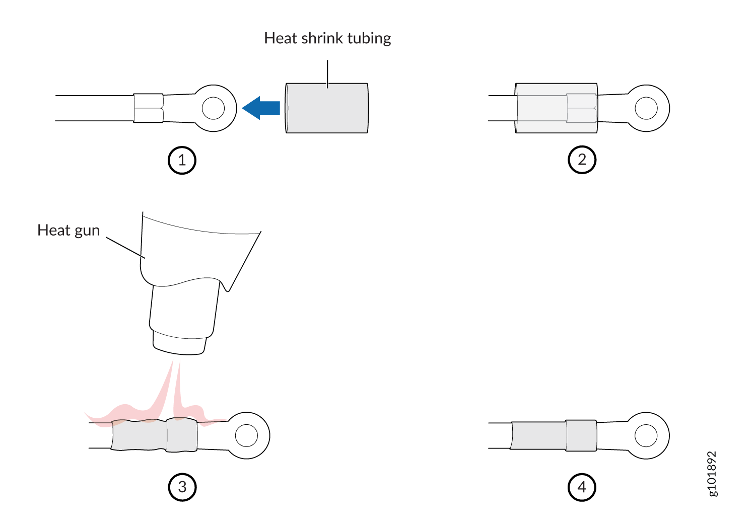
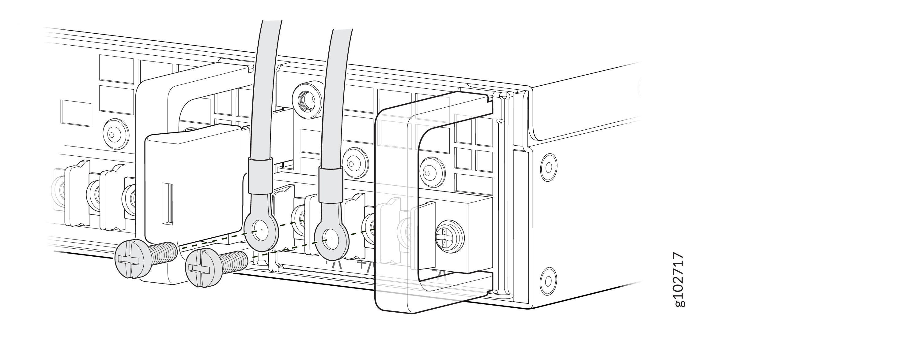
-
-
Remove the screws and square washers from the terminals, using a number 2
Phillips (+) screwdriver.
Figure 4: Disconnect/Reconnect DC Terminals
If power is lost to the SSR1400, the Power-On/Power-Off state is retained. For example, if the device loses power while the device is on, when power returns, the device will still be in the On state.
Power On the SSR1400
To power on the SSR1400
The device starts automatically as the power supply completes its startup sequence. The PWR LED (on the front panel of the chassis) lights up during startup and remains solid when the SSR1400 is operating normally.
Power Off the SSR1400
You can power off the SSR1400 in one of the following ways:
-
Graceful shutdown—You can do a graceful shutdown in two ways:
-
Use the Linux
poweroffcommand at the Console. The appliance begins gracefully shutting down the operating system and then powers itself off. -
Press and hold the power switch for less than 4 seconds. The appliance begins gracefully shutting down the operating system and then powers itself off.
CAUTION:Use the graceful shutdown method to power off or reboot the appliance.
-
-
Forced shutdown—Press and hold the power switch for more than 4 seconds, then release. The appliance immediately powers itself off without shutting down the operating system.
CAUTION:Forced shutdown can result in data loss and corruption of the file system.
Use the forced shutdown method as a last resort to recover appliance if the appliance operating system is not responding to the graceful shutdown method.
Do not press the power switch while the appliance is shutting down.
To remove power completely from the appliance, unplug the power cord or switch off the power source.
After powering off a power supply, wait at least 10 seconds before turning it back on.
After powering on a power supply, wait at least 10 seconds before turning it off.