Step 1: Begin
In this guide, we provide a simple, three-step path, to quickly get you up and running with your new EX4100 and EX4100-F switch. We’ve simplified and shortened the installation and configuration steps, and included how-to videos. You’ll learn how to install an AC-powered EX4100 and EX4100-F in a two-post rack, install an EX4100-F-12P and EX4100-F-12T on a desk, power it up, and configure basic settings.
Are you interested in getting hands-on experience with the topics and operations covered in this guide? Visit Juniper Networks Virtual Labs and reserve your free sandbox today! You’ll find the Junos Day One Experience sandbox in the stand alone category. Because EX switches are not virtualized, in the demonstration, focus on the virtual QFX device. Both the EX and QFX switches are configured with the same Junos commands.
Meet the EX4100 and EX4100-F Ethernet Switches
The Juniper Networks® EX4100 and EX4100-F Ethernet Switches are two separate EX switch model families. The EX4100 switch models have field-replaceable units (FRUs) such as AC/DC power supplies and fan modules. The EX4100-F (fixed-form) switch models, namely, EX4100-F-24T, EX4100-F-24P, EX4100-F-48T, and EX4100-F-48P have built-in power supplies and fan modules. The EX4100-F switch models, namely, EX4100-F-12T and EX4100-F-12P use external power supply adaptors for drawing power, and are fanless models with natural convection cooling.
They are built to be cost-effective solutions for today’s demanding converged data, voice, and video enterprise access network requirements. The 1-RU switches are perfect for campus wiring closet deployments. They offer levels of performance and management previously available only with high-end access switches. The EX4100 and EX4100-F switches have Power over Ethernet (PoE+/PoE++) ports for powering network devices connected to the switches.
In this guide, we show you how to install a EX4100 and EX4100-F switch model with an AC power supply. If you need instructions for installing fans and power supplies on EX4100 switch models see the EX4100 and EX4100-F Switch Hardware Guide.
EX4100 switch models are:
Gigabit switch models
-
EX4100-24P, EX4100-24T, EX4100-48P, and EX4100-48T. See EX4100-24P, EX4100-24T, EX4100-48P, and EX4100-48T Switches.
Multigigabit switch models
-
EX4100-24MP and EX4100-48MP. See EX4100-24MP and EX4100-48MP Switches.
EX4100-F (fixed-form) switch models are:
Fanless models using external power supply adaptors
-
EX4100-F-12T and EX4100-F-12P. See EX4100-F-12P and EX4100-F-12T Switches.
Models with built-in fans and power supplies
-
EX4100-F-24T, EX4100-F-24P, EX4100-F-48P, and EX4100-F-48T. See EX4100-F-24P, EX4100-F-24T, EX4100-F-48P, and EX4100-F-48T Switches.
EX4100 and EX4100-F switches are cloud native switches that you can onboard and manage in a cloud network by using Juniper Mist™ cloud. EX4100 and EX4100-F switches support Virtual Chassis technology, making it easy for you to scale the network without increasing the number of devices to manage. The EX4100 and EX4100-F switches are available in 12-port, 24-port and 48-port models.
EX4100-24P, EX4100-24T, EX4100-48P, and EX4100-48T Switches
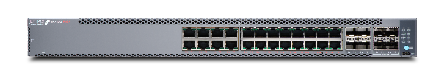
EX4100-24P
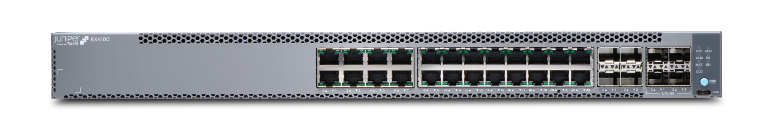
EX4100-24T
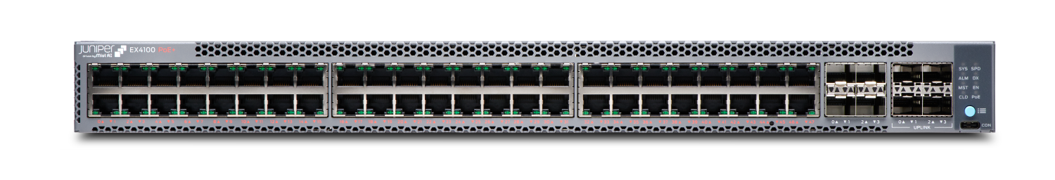
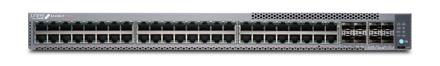
EX4100-48P
EX4100-48T
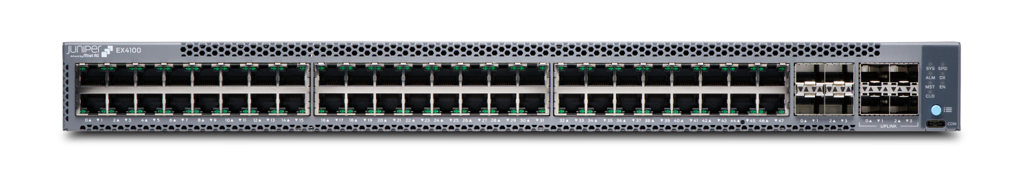
Here are the port configuration details for the EX4100 gigabit switch models:
| Models | Access Ports |
|---|---|
|
EX4100-24P, EX4100-24T, EX4100-24T-DC |
Twenty four 10/100/1000-Mbps RJ-45 ports, four 10/25 Gbps SFP28 Virtual Chassis ports, and four 1/10 Gbps SFP+ uplink ports on the front panel. EX4100-24P has PoE+ enabled ports. |
|
EX4100-48P, EX4100-48T, EX4100-48T-AFI, EX4100-48T-DC |
Forty eight 10/100/1000-Mbps RJ-45 ports, four 10/25 Gbps SFP28 Virtual Chassis ports, and four 1/10 Gbps SFP+ uplink ports on the front panel. EX4100-48P has PoE+ enabled ports. |
EX4100-24MP and EX4100-48MP Switches
EX4100-24MP
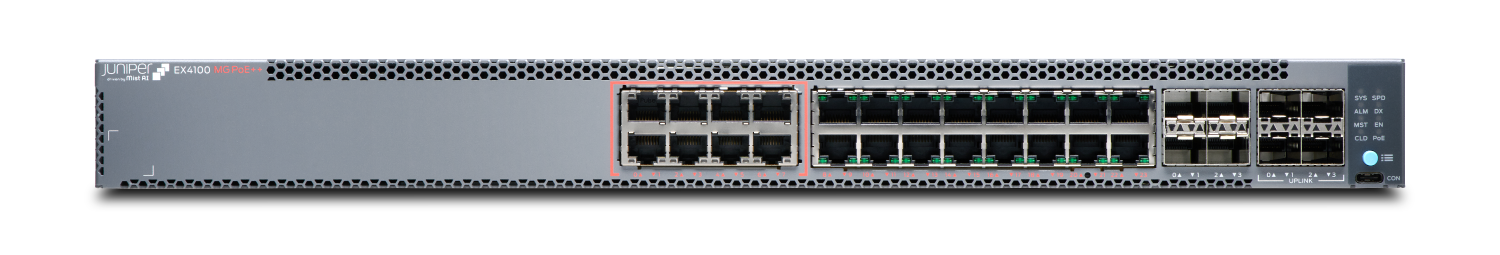
EX4100-48MP
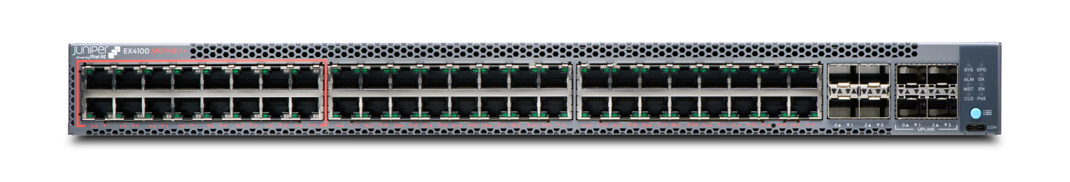
Here are the port configuration details for the EX4100 multigigabit switch models:
| Models | Access Ports |
|---|---|
|
EX4100-24MP |
Eight 1/2.5/5/10 Gbps and sixteen 1 Gbps RJ-45 ports; four 10/25 Gbps SFP28 Virtual Chassis ports, and four 1/10 Gbps SFP+ uplink ports on the front panel. EX4100-24MP has PoE++ enabled ports. |
|
EX4100-48MP |
Sixteen 1/2.5 Gbps and thirty-two 1 Gbps RJ-45 ports; four 10/25 Gbps SFP28 Virtual Chassis ports, and four 1/10 Gbps SFP+ uplink ports on the front panel. EX4100-48MP has PoE++ enabled ports. |
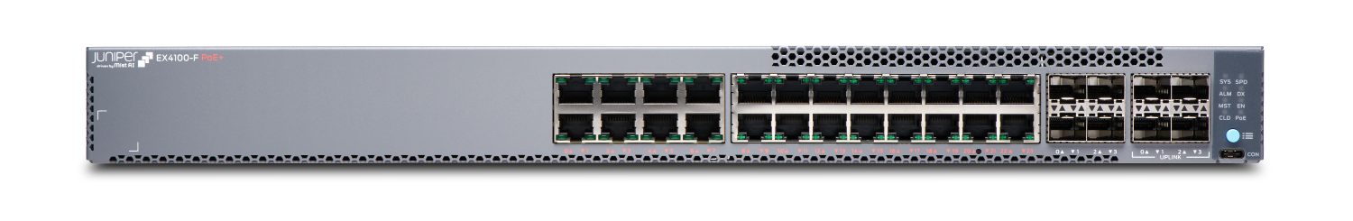
EX4100-F-12P and EX4100-F-12T Switches
EX4100-F-12P

EX4100-F-12T

Here are the port configuration details for the EX4100-F-12P and EX4100-F-12T switch models:
| Models | Access Ports |
|---|---|
|
EX4100-F-12P and EX4100-F-12T |
Twelve 1 Gbps RJ-45 ports, four 10 Gbps SFP+ Virtual Chassis ports on the front panel. Two 1/2.5/5/10 Gbps multigigabit RJ-45 uplink ports on the rear panel. Only EX4100-F-12P has PoE+ enabled ports. |
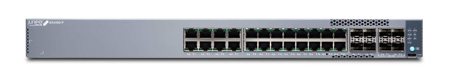
EX4100-F-24P, EX4100-F-24T, EX4100-F-48P, and EX4100-F-48T Switches
EX4100-F-24P
EX4100-F-24T
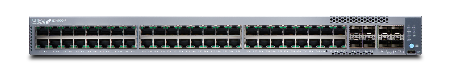
EX4100-F-48P
EX4100-F-48T
Here are the port configuration details for the EX4100-F-24P, EX4100-F-24T, EX4100-F-48P, and EX4100-F-48T switch models:
| Models | Access Ports |
|---|---|
|
EX4100-F-24P and EX4100-F-24T |
Twenty four 10/100/1000-Mbps RJ-45 ports, four 1/10 Gbps SFP+ Virtual Chassis ports, and four 10 Gbps SFP+ uplink ports on the front panel. Only EX4100-F-24P has PoE+ enabled ports. |
|
EX4100-F-48P and EX4100-F-48T |
Forty eight 10/100/1000-Mbps RJ-45 ports, four 1/10 Gbps SFP+ Virtual Chassis ports, and four 10 Gbps SFP+ uplink ports on the front panel. Only EX4100-F-48P has PoE+ enabled ports. |
Install the EX4100 and EX4100-F
What's in the Box?
-
EX4100 switch with two preinstalled fan modules and one preinstalled power supply unit or EX4100-F switch with built-in fans and power supplies or EX4100-F fanless switch that uses an external power supply adaptor.
-
One AC power cord appropriate for your geographical location.
-
AC power cord retainer (not provided for EX4100-F-12P and EX4100-F-12T switches)
-
Eight preinstalled dust covers for SFP ports (four for EX4100-F-12P and EX4100-F-12T switches)
-
Four rubber feet (not required for EX4100-F-12P and EX4100-F-12T switches)
-
RJ-45 cable and RJ-45 to DB-9 serial port adapter
What Else Do I Need?
-
Someone to help you secure the switch to the rack
-
Mounting screws to secure the EX4100, EX4100-F-24P, EX4100-F-24T, EX4100-F-48P, and EX4100-F-48T switches to the rack
-
A number two Phillips (+) screwdriver
-
A serial-to-USB adapter (if your laptop doesn’t have a serial port)
-
An electrostatic discharge (ESD) grounding strap
-
A management host such as a laptop or desktop PC
-
Two M5X10mm screws with washers to secure the grounding lug (two 10-32 screws for EX4100-F-12P and EX4100-F-12T switches)
-
A grounding cable: 8 AWG (2 mm²), minimum 90° C wire, or as permitted by the local code, with a Panduit LCD8-14A-L or equivalent lug attached (LCD8-10A-L for EX4100-F-12P and EX4100-F-12T switches)
Have a licensed electrician attach the appropriate grounding lug to the grounding cable that you supply. Using a grounding cable with an incorrectly attached lug can damage the switch.
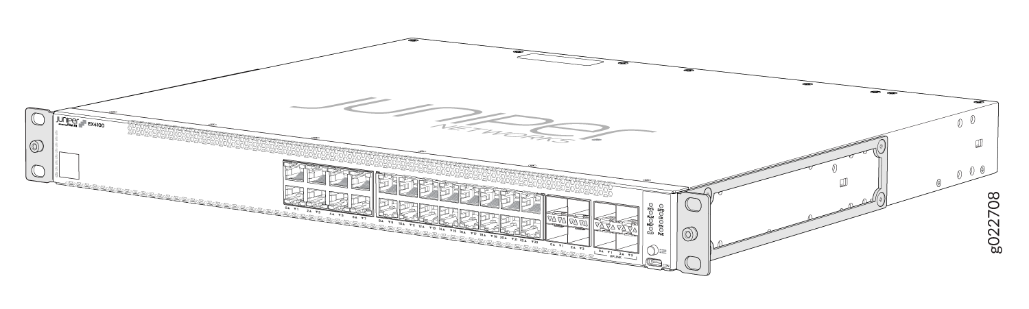
Install the EX4100 and EX4100-F Switch in a Rack
Before you start the installation, ensure to review the General Safety Guidelines and Warnings. Also, have someone available to help you secure the switch to the rack.
Desktop mounting is the default mounting option for EX4100-F-12P and EX4100-F-12T switches. Refer Install the EX4100-F-12P and EX4100-F-12T Switch on a Desk. The EX4100-F-12P and EX4100-F-12T switches have various other mounting options too, namely, two-post rack, under-the-desk, wall, magnet, and DIN rail mounting. See Unpack and Mount an EX4100 and EX4100-F Switch to read more.
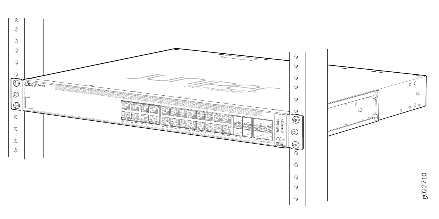
The mounting kit that ships in the box has the brackets you need to install the switch in a two-post rack. We’ll walk you through how to install the switch in a two-post rack. The following are instructions on how to install the EX4100 gigabit and EX4100 multigigabit switch models, and EX4100-F switch models with built-fans/power supplies in a rack.
If you want to install the switch in a four-post rack or on the wall , you’ll need to order separate mounting kits. The four-post rack mount kit also has brackets for mounting the switch in a recessed position in the rack.
-
Place the switch on a flat, stable surface.
-
Attach an ESD grounding strap to your bare wrist, and connect the strap to the ESD grounding point on the switch.
-
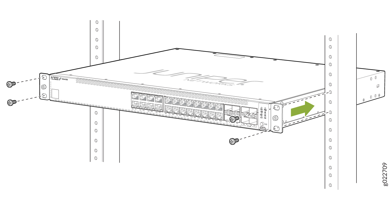
Lift the switch and position it in the rack. Position the switch so that the AIR IN labels on the fan modules are facing the cold aisle or the AIR OUT labels on the fan modules are facing the hot aisle. Line up the bottom hole in each mounting bracket with a hole in each rack post, ensuring that the switch is level.
-
While you’re holding the switch in place, have a second person insert and tighten the rack mount screws to secure the mounting brackets to the rack posts. Tighten the screws in the two bottom holes first, and then tighten the screws in the two top holes.
-
Check that the mounting brackets on each side of the rack are lined up with each other.
Install the EX4100-F-12P and EX4100-F-12T Switch on a Desk
To install the EX4100-F-12P and EX4100-F-12T switch on a desk:
Place the switch and its adapter on the desk or the level surface. The following image shows an EX4100-F-12P switch mounted on a desk. The same procedure applies to an EX4100-F-12T switch as well.

-
Ensure that the switch rests firmly on the desk or level surface.
Allow sufficient space of 6 inches all around the switch for cooling. Insufficient space can lead to overheating of the switch chassis.
Power On
Power on the EX4100, EX4100-F-24P, EX4100-F-24T, EX4100-F-48P, and EX4100-F-48T Switches
Here's how to connect the switch to AC power:
-
Attach an ESD grounding strap to your bare wrist, and connect the strap to the ESD grounding point on the switch.
-
Connect one end of the grounding cable to a proper earth ground, such as the rack .
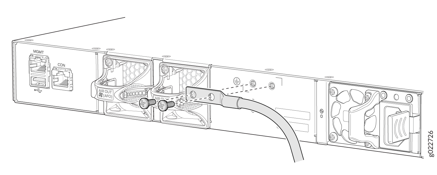
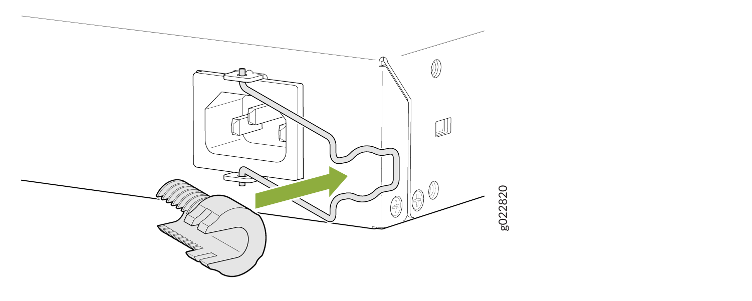
Place the grounding lug (that's attached to the grounding cable) over the protective earthing terminal on the rear panel as depicted in the following figures.
EX4100 switch models
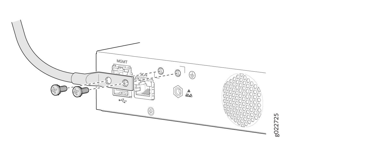
EX4100-F-24T, EX4100-F-24P, EX4100-F-48T, and EX4100-F-48P switch models
-
Secure the grounding lug to the protective earthing terminal using the two M5X10 mm screws with washer.
-
Dress the grounding cable. Ensure that the cable doesn’t block access to or touch other device components, and that it doesn’t drape where people could trip over it.
-
Ensure that the power supply is fully inserted in the rear panel of the switch.
-
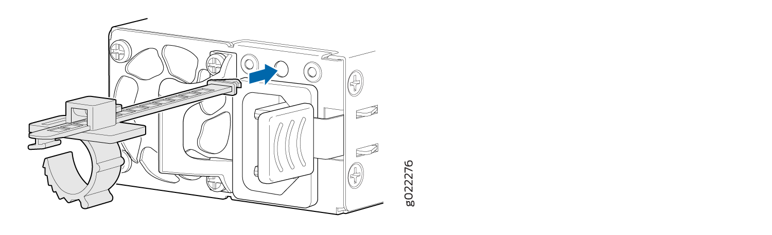
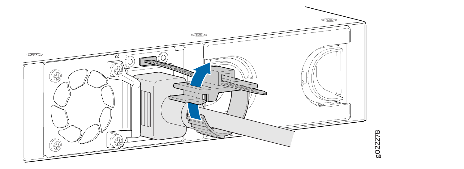
For EX4100 switches, on the rear panel, connect the power cord retainer clip to the AC power supply:
Push the end of the power cord retainer strip into the slot above the power cord socket until the strip snaps into place. Ensure that the loop in the retainer strip faces the power cord. The power cord retainer clip extends out of the chassis by 3 in. (7.62 cm).
-
Press the small tab on the retainer strip to loosen the loop. Slide the loop until there's enough space to insert the power cord coupler into the power cord socket.
-
Plug in the power cord to the power cord socket.
-
Slide the loop toward the power supply until it's snug against the base of the coupler.
Press the tab on the loop and draw out the loop into a tight circle.
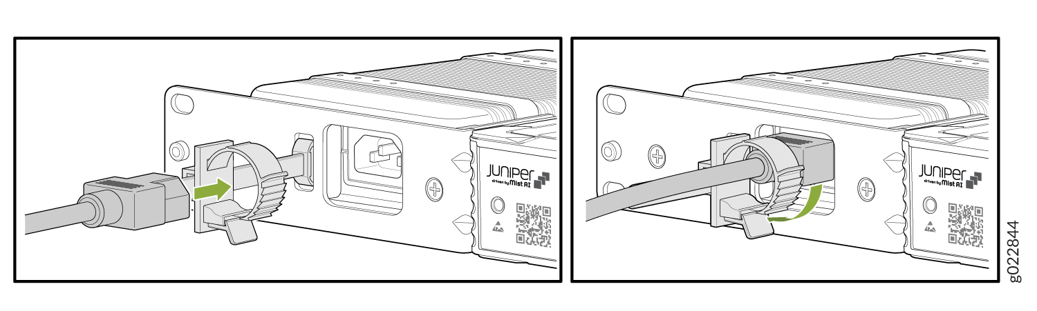
For EX4100-F switches push the power cord into the slot in the adjustment nut of the power cord retainer clip. Turn the nut until it is tight against the base of the coupler and the slot in the nut is turned 90° from the top of the switch.

-
If the AC power source outlet has a power switch, turn it off.
-
Insert the power cord plug into an AC power source outlet.
-
If the AC power source outlet has a power switch, turn it on. The switch powers on as soon as you plug it in.
-
For EX4100 switches check to see that the DC OK LED on the power supply is lit steadily green. If not, disconnect the power supply from the power source. You’ll need to replace the power supply (see Maintain the EX4100 Power System in the EX4100 and EX4100-F Switch Hardware Guide
Power On the EX4100-F-12P and EX4100-F-12T Switch
Here's how to connect the switch to AC power:
EX4100-F-12P can also be powered by another PoE++ EX4100-MP switch. See Powered Device in the EX4100 and EX4100-F Switch Hardware Guide.
-
Attach an ESD grounding strap to your bare wrist, and connect the strap to the ESD grounding point on the switch.
-
Connect one end of the grounding cable to a proper earth ground, such as the rack.
Place the grounding lug (that's attached to the grounding cable) over the protective earthing terminal on the rear panel as depicted in the following figure. Secure the grounding lug to the protective earthing terminal using the two #10-32 screws with washer.

-
Push the end of the power cord retainer strip into the slot beside the power cord inlet until the strip snaps into place. See figure in step 9.
Note:Note that steps 4, 5, 7, 8, and 9 are performed when using the RMK (rack mounting kit). These steps are not applicable for desktop mounting and also mounting of the switch using RME (rack mounting ears) kit.
-
Press the small tab on the retainer strip to loosen the loop. Slide the loop until you have enough space to insert the power cord coupler into the power cord inlet. See figure in step 9.
-
Locate the power cord or cords shipped with the switch. The cords have plugs appropriate for your geographical location.
-
Insert the power cord coupler firmly into the power cord inlet. See figure in step 9.
-
Slide the loop toward the power supply until it is snug against the base of the coupler. See figure in step 9.
Press the tab on the loop and draw out the loop into a tight circle.
Insert the power cord attached to the power supply to the DC inlet of the switch.
Connect Power Supply Adaptor to DC Inlet of the EX4100-F-12P Switch

Connect Power Supply Adaptor to DC Inlet of the EX4100-F-12T Switch

-
Switch off the AC power source outlet.
-
Insert the power cord plug of the power cord that was attached to the power inlet into the AC power source outlet.
-
Switch on the AC power source outlet.