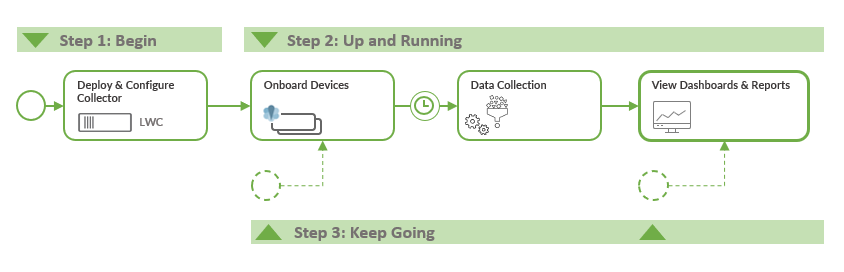
Step 1: Begin
In this guide, we provide a simple, three-step path, to quickly get you up and running with the Juniper Support Insight (JSI) solution. We’ve simplified and shortened the installation and configuration steps.
Meet Juniper Support Insights
Juniper® Support Insights (JSI) is a cloud-based support solution that gives IT and network operations teams operational insights into their networks. JSI aims to transform the customer support experience by providing Juniper and its customers with insights that help improve the network performance and uptime. JSI collects data from Junos OS-based devices on customer networks, correlates it with Juniper-specific knowledge (such as service contract status, and End of Life and End of Support states), and then curates that into actionable insights.
At a high level, getting started with the JSI solution involves the following steps:
-
Installing and configuring a Lightweight Collector (LWC) device
-
Onboarding a set of Junos devices to JSI to initiate data collection
-
Viewing notifications about device onboarding and data collection
-
Viewing operational dashboards and reports
This Day One+ guide assumes that you have ordered the JSI-LWC solution, which is available as part of Juniper Care support service, and that you have an active contract. If you have not ordered the solution, please contact your Juniper Account or Services teams. Accessing and using JSI is subject to the Juniper Master Procurement and License Agreement (MPLA). For general information on JSI, see Juniper Support Insights Datasheet.
Install the Lightweight Collector
The Lightweight Collector (LWC) is a data collection tool that gathers operational data from Juniper devices on customer networks. JSI uses this data to provide IT and network operations teams with actionable operational insights into the onboarded Juniper devices on customer networks.
You can install the LWC on your desktop, in a two-post or four-post rack. The accessory kit that ships in the box has the brackets you need to install the LWC in a two-post rack. In this guide, we show you how to install the LWC in a two-post rack. If you need to install the LWC in a four-post rack, you’ll need to order a four-post rack mount kit.
What's in the Box?
-
The LWC device
-
AC power cord for your geographic location
-
AC power cord retainer clip
-
Two rack mount brackets
-
Eight mounting screws to attach the mounting brackets to the LWC
-
Two SFP modules (2 x CTP-SFP-1GE-T)
-
RJ-45 cable with a DB-9 to RJ-45 serial port adapter
-
Four rubber feet (for desktop installation)
What Else Do I Need?
- Someone to help you mount the LWC in the rack.
- Four rack mount screws to secure the mounting brackets to the rack
- A number 2 Phillips (+) screwdriver
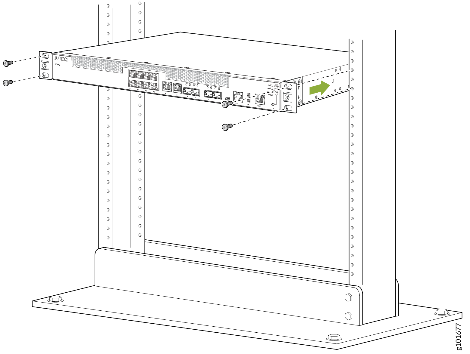
Mount a Lightweight Collector on Two Posts in a Rack
You can mount a Lightweight Collector (LWC) on two posts of a 19-in. rack (either a two-post or a four-post rack).
Here's how to mount the LWC on two posts in a rack:
-
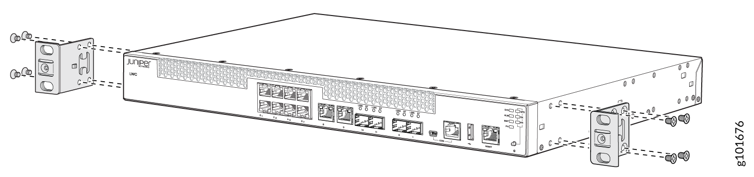
Secure the mounting brackets to the sides of the LWC using eight screws and
the screwdriver. You’ll notice there are three locations on the side panel
where you can attach the mounting brackets: front, center, and rear. Attach
the mounting brackets to the location that best suits where you want the LWC
to sit in the rack.
-
Lift the LWC and position it in the rack. Line up the bottom hole in each
mounting bracket with a hole in each rack rail, making sure the LWC is
level.
Power On
- Attach a grounding cable to earth ground and then attach it to the Lightweight Collector's (LWC's) grounding points.
- Turn off the power switch on the LWC rear panel.
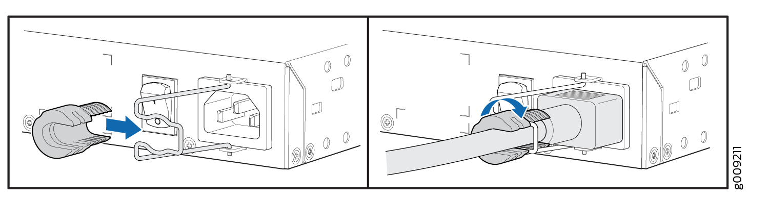
- On the rear panel, insert the L-shaped ends of the power cord retainer clip into the holes in the bracket on the power socket. The power cord retainer clip extends out of the chassis by 3 inches.
- Insert the power cord coupler firmly into the power socket.
- Push the power cord into the slot in the adjustment nut of the power cord
retainer clip. Turn the nut until it is tight against the base of the
coupler and the slot in the nut is turned 90° from the top of the
device.
- If the AC power source outlet has a power switch, turn it off.
- Plug in the AC power cord to the AC power source outlet.
- Turn on the power switch on the LWC's rear panel.
- If the AC power source outlet has a power switch, turn it on.
- Verify that the power LED on the LWC front panel is green.
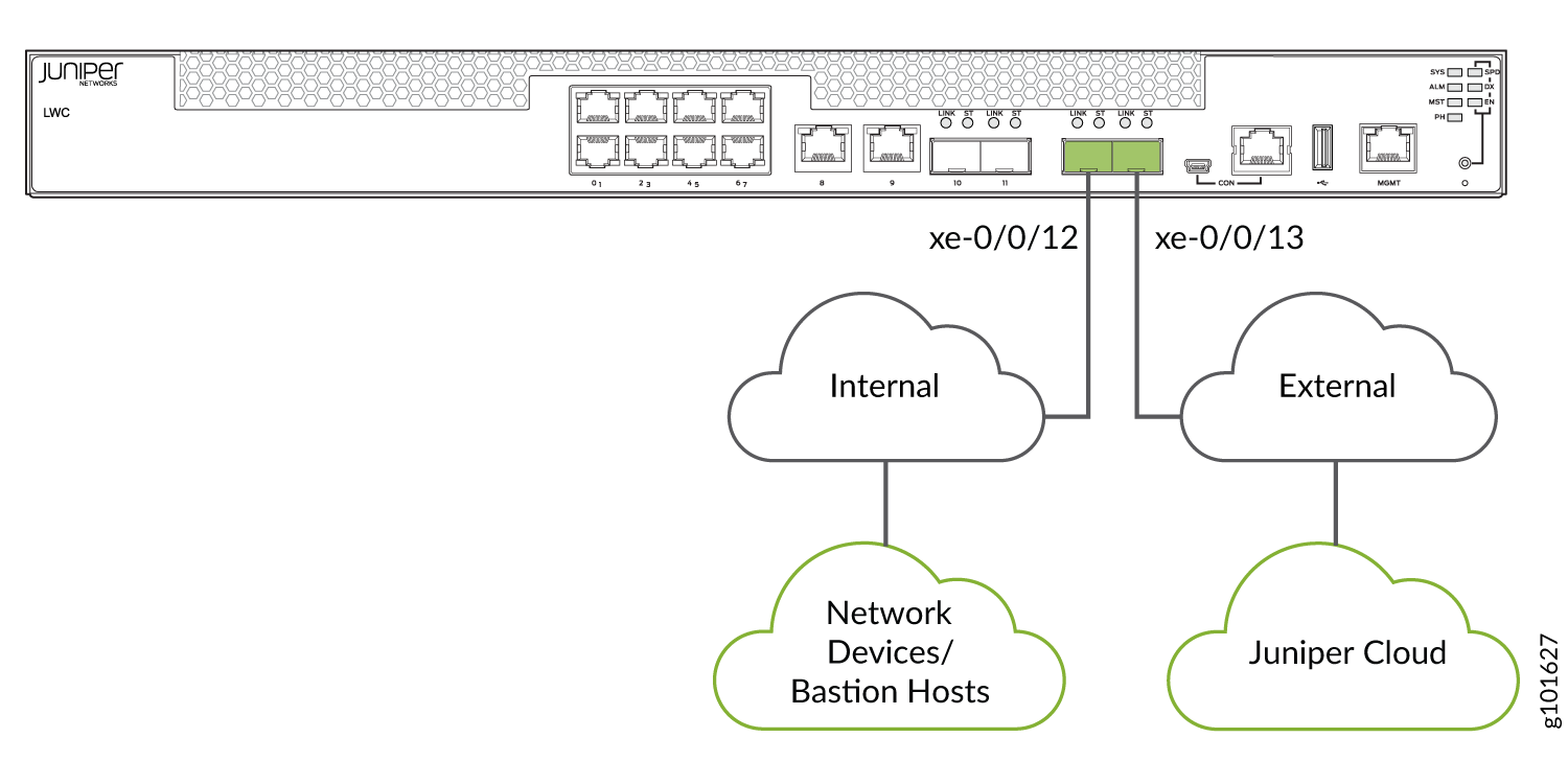
Connect the Lightweight Collector to the Networks
The Lightweight Collector (LWC) uses an internal network port to access the Juniper devices on your network, and an external network port to access Juniper Cloud.
Here's how to connect the LWC to the internal and external network:
- Connect the internal network to the 1/10-Gigabit SFP+ port 0 on the LWC. The interface name is xe-0/0/12.
- Connect the external network to the 1/10-Gigabit SFP+ port 1 on the LWC. The interface name is xe-0/0/13.
Configure the Lightweight Collector
Before you configure the Lightweight Collector (LWC), refer to the Internal and External Network Requirements.
We've preconfigured the LWC to support IPv4 and Dynamic Host Configuration Protocol (DHCP) on both the internal and external network ports. When you power on the LWC after completing the required cabling, a zero touch experience (ZTE) process to provision the device is initiated. Successful completion of the ZTE results in the device establishing IP connectivity on both the ports. It also results in the external port on the device establishing connectivity to Juniper Cloud via discoverable reachability to the Internet. If the device fails to automatically establish IP connectivity and reachability to the Internet, you must configure the LWC device manually, by using the LWC captive portal.
Here's how to configure the LWC device manually, by using the LWC captive portal:
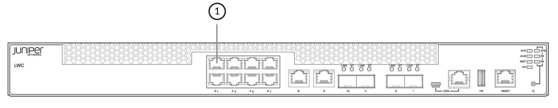
-
Connect the computer to the port ge-0/0/0 on the LWC (labeled as
1 in the image below) using an Ethernet cable
(RJ-45). The LWC assigns an IP address to the Ethernet interface of your
computer through DHCP.
-
Enter the LWC serial number in the Serial Number
field and then click Submit to log in.
On successful login, the JSI Data Collector page appears.
 Note:
Note:If the default DHCP configuration on the LWC is successful, the captive portal shows the LWC's connection status as connected, and populates the fields in all the configurations sections appropriately.
Click Refresh to refresh the current connection states.
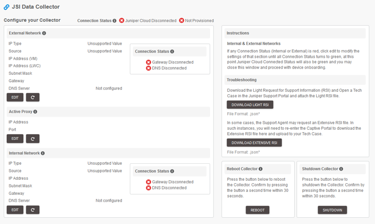
The JSI Data Collector page displays configuration sections for the following:
-
External Network—Lets you configure external network port that connects the LWC to the Juniper's Cloud. Supports DHCP and static addressing. The External Network configuration is used to perform device provisioning.
-
Internal Networks—Lets you configure the internal network port that connects the LWC to the Juniper devices on the network. Supports DHCP and static addressing.
-
Active Proxy—Lets you configure the active proxy IP address as well as the port number if your network infrastructure controls access to the Internet though an active proxy. You need not configure this element if you are not using an active proxy.
-
-
After modifying the fields, click Update to apply
the changes and return to the homepage (the JSI Data Collector page).
If you want to discard your changes, click Cancel.
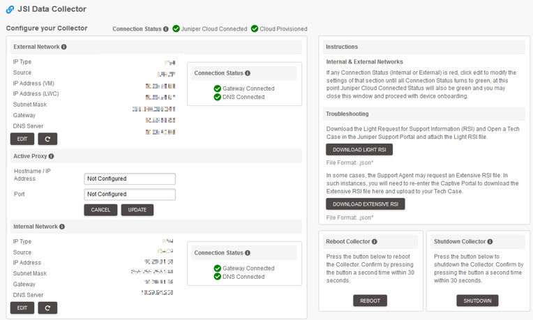
If the LWC connects to the gateway and DNS successfully, the respective configuration element (internal or external network section) on the JSI Data Collector homepage shows the connection status as Gateway Connected and DNS Connected with green tick marks against them.
The JSI Data Collector homepage displays the Connection Status as:
-
Juniper Cloud Connected if the external connectivity to the Juniper Cloud is established and the active proxy (if applicable) settings are correctly configured.
-
Cloud Provisioned if the device is connected to Juniper Cloud and has completed the Zero Touch Experience (ZTE) process. After the Cloud connection status becomes Juniper Cloud Connected, it takes about 10 minutes for the provision status to become Cloud Provisioned.
The following image shows how the JSI Data Collector page appears when the LWC is connected successfully.
If the LWC does not connect to the cloud, click Download Light RSI to download the light RSI file, create a Tech Case in the Juniper Support Portal, and attach the downloaded RSI file to the case.
In some cases, the Juniper support engineer might ask you to attach the Extensive RSI file to the case. To download it, click the Download Extensive RSI.
The Juniper support engineer might ask you to reboot the LWC for troubleshooting. To reboot the LWC, click REBOOT.
If you want to shut down the LWC, click SHUTDOWN.
-