Up and Running
Onboard Devices
Onboard the devices that you want Paragon Automation to monitor and manage. You can either discover devices already active in your network (Discover Devices option) or add new devices by using Zero Touch Provisioning (ZTP) (Add New Devices option). For information on ZTP, see Zero-Touch Provisioning Overview.
Paragon Automation supports Juniper Networks, Cisco IOS XR, and Nokia devices. For a complete list of supported devices, see Supported Devices and OS Versions. For new Juniper devices, follow the instructions in the hardware documentation to unbox the device, mount it on a rack, and power on the device. For details about installing a device, see the device's Hardware Guide on the TechLibrary or the device’s Quick Start Guide. Search for the device in the search box provided or navigate to Routing > View More, Switching > View More, or Security > View More.
Use one of the following sequence of steps to onboard your devices:
Discover Devices
To onboard devices already active in your network.
-
On the Devices page (Configuration > Devices), click the Add (+) icon.
The Add Devices page appears.
- Select the Discover Devices option, which is highlighted by default, to discover devices already active in your network.
- You can either enter device details manually or import the device details
from a comma-separated values (CSV) file:
- To enter the device details manually, select Enter Manually, which is the default. Go to Step 4.
- To enter the device details using a CSV file:
- Select Import From File, and click
Browse.Tip:
Click the Download Sample CSV File link to download a sample CSV and use the sample file to create your own CSV file.
- In the File Upload dialog box, select the CSV file to
upload, and click Open.
Paragon Automation parses the file and displays the device details in one or more Targets and Credentials sections.
- (Optional) Confirm that the device details and credentials
were imported correctly.
Go to Step 10.
- Select Import From File, and click
Browse.
- Click the Managed Status toggle
button to specify whether the device is managed or unmanaged:
- Managed: Indicates that Paragon Automation can discover the device, configure and monitor the device, and perform device operations (such as rebooting and pushing configurations to the device). This is the default option.
- Unmanaged: Indicates that Paragon Automation cannot discover the device by using NETCONF.
- In the Hostname / IP Targets field, enter the
hostnames or IP addresses of the devices that you want Paragon Automation to
discover.
You can enter multiple hostnames or IP addresses by typing each entry and then pressing Enter.
- (Optional) You can also select devices from the list of devices discovered
by Paragon Pathfinder (using BGP-LS):Note:
For a device to be discovered by Paragon Automation by using BGP-LS, the IP addresses of the device must be routable from Paragon Pathfinder and NETCONF must be enabled on the device.
- Click the Add targets from topology to this
list link.
The Add Topology Targets page appears.
- Select the check boxes corresponding to the devices that you want to
add, and click Add.
You are returned to the Add Devices page. The IP addresses of the devices that you added appear in the Hostname / IP Targets field.
- Click the Add targets from topology to this
list link.
- In the Device Credentials field, enter the username
and password.Note:
For Junos OS devices, we recommend that you use a non-root account with super user permissions. Ensure that you configure this account on each device that you discover or add.
-
To use RADIUS credentials for managing the device, toggle the Use Same Credentials for Managing the Device button on. To use Paragon Automation generated credentials for managing the device, toggle the Use Same Credentials for Managing the Device button off.
Note: NOTE:To use RADIUS authentication on the device, you must configure information about the RADIUS servers on the network. For more information, see Radius Authentication.
- Click OK.
Paragon Automation triggers a device discovery job and displays a confirmation message with a link to the job. You are returned to the Devices page.
-
(Optional) Click the job ID link on the confirmation message (or on the Jobs page [Monitor > Jobs]) to open the Job Status page, where you can monitor the status of the device discovery.
-
After the job finishes, go to the Devices page and verify that the devices are discovered correctly.
Note:- For managed devices, the Management Status should be Up, indicating that Paragon Automation established a connection with the device. In addition, the Sync Status should be In Sync, indicating that the configuration and the inventory data in Paragon Automation and on the device are in sync.
- For unmanaged devices, the Management Status should be Unmanaged, and the Sync Status should be Unknown. The Sync Status Unknown indicates that Paragon Automation added the device to its database, but that no NETCONF session was created to synchronize the configuration and the status.
Add New Devices
To onboard devices using ZTP:
To use ZTP, the devices must be present in the same subnet as Paragon Automation. To onboard devices in a different subnet, you must install and run DHCP Relay to connect the devices with Paragon Automation. See Configure a DHCP Relay for ZTP for more information.
-
On the Devices page (Configuration > Devices), click the Add (+) icon.
The Add Devices page appears.
- Select the Add New Devices option.
-
Enter the root password and the range of IP addresses for management connectivity.
- You can either enter device details manually or import the device details
from a comma-separated values (CSV) file:
- To enter the device details manually, select Enter Manually, which is the default. Go to Step 5.
- To enter the device details using a CSV file:
- Select Import From File, and click
Browse.Tip:
Click the Download Sample CSV File link to download a sample CSV and use the sample file to create your own CSV file.
- In the File Upload dialog box, select the CSV file to upload, and click Open.
- (Optional) Confirm that the device details and credentials
were imported correctly.
Go to Step 12.
- Select Import From File, and click
Browse.
- Select the device family that you want to add from the Device Family list.
- Select the device model that you want to add from the Device Model list.
- Select the Junos image that the device must use from the JUNOS Image list. The default is Use Image on Device indicating that the device is added to Paragon Automation with the image already existing in it.
- In the Device Serial Numbers field, enter the serial number of the device that you want to add. To add more than one serial number, enter the serial number of each device that you want to add and then press Enter.
-
When the common root password is disabled, enter the root password to be assigned to the device in the Root Password field.
-
(Optional) Click the Add (+) icon to add more device models for discovery.
- Click OK.
Paragon Automation triggers a device discovery job and displays a confirmation message with a link to the job. You are returned to the Devices page.
-
(Optional) Click the job ID link on the confirmation message (or on the Jobs page [Monitor > Jobs]) to open the Job Status page, where you can monitor the status of the device discovery.
-
After the job finishes, go to the Devices page and verify that the devices are discovered correctly.
Now that you've onboarded the devices, you can configure the devices.
Configure Devices
These configurations will be used by Paragon Pathfinder and Paragon Insights.
- On the Devices page (Configuration > Devices), select
the device, and click the Edit (pencil) icon.
The Edit Device-Name page appears.
- Configure the parameters related to PCEP in the Protocols >
PCEP section.
- Specify which PCEP version to use from the
Version list:
- Select Non-RFC, which is the default
option, to run in non-RFC 8231/8281 compliance mode.
You can use this option for devices running Junos OS versions 15.x through versions 19.x.
- Select RFC Compliant to run in RFC 8231/8281 compliance mode. You can use this option for any vendor's devices that conform to RFC 8231/8281. For example, Juniper devices running Junos OS versions 19.x and later.
- Select 3rd party PCC for older versions of Cisco devices.
- Select Non-RFC, which is the default
option, to run in non-RFC 8231/8281 compliance mode.
- In the IP Address field, enter the IP address used by the device to connect to Paragon Automation for managing LSPs.
-
Enter the MD5 key to secure PCEP sessions between Paragon Pathfinder and the device. You must configure the same key on the router as well.
- Specify which PCEP version to use from the
Version list:
- Configure the NETCONF parameters in the Protocols >
Netconf section.
- Enabled: Click the toggle button to enable NETCONF on the device.
- Bulk Commit: Click the toggle button to enable
NETCONF bulk commit. If you enable bulk commit, you can provision
multiple LSPs in a single commit instead of using multiple commits.Note:
- When you use point to multipoint (P2MP) LSPs on Juniper devices, you must enable bulk commit to enable support for P2MP LSP provisioning on the devices.
- In other cases, enabling bulk commit is optional, and you can use bulk commit if you want to improve provisioning efficiency.
-
In the Retry Count field, enter the number of attempts to establish a NETCONF connection with the device.
- iAgent/Netconf Port: Enter the port number (on
the device) to be used for NETCONF. This port should not be used for any
other service.
The default port number is 830 for Juniper Networks devices and 22 for other devices.
- (Optional) If you want Pathfinder to receive telemetry data from devices,
configure the system identifier (for Junos Telemetry Interface [JTI]) and the
management IP address in the Device ID Details section.Note:
For the JTI system identifier, use the format device-host-name:jti-ip-address, where:
- device-host-name is the hostname of the device.
- jti-ip-address is the IP address
(
local-addressstatement) that is configured for theexport profilein Junos OS.
For information on identifying the jti-ip-address, see export-profile (Junos Telemetry Interface).
- Click OK to save your changes.
For details on configuring device parameters, see Edit Devices.
Configure Paragon Pathfinder
Configure Paragon Pathfinder to acquire network topology and provision add LSPs. You can use Paragon Pathfinder features if you have installed the required license.
- Add the devices to the controller device group:
- On the Device Group Configuration page (Configuration >
Device Groups), select the
controller device group, and click the Edit
(pencil) icon.
The Edit Device Group page appears.
- In the Devices field, select the devices that Paragon Automation previously discovered, and then save and deploy the changes.
For details, see Edit a Device Group.
- On the Device Group Configuration page (Configuration >
Device Groups), select the
controller device group, and click the Edit
(pencil) icon.
- Run the device collection task:
- On the Task Scheduler page (Administration > Task
Scheduler), click the Add (+)
icon.
The Create New Task wizard appears.
- In Step 1 of the wizard, specify the following and click
Next.
- In the Name field, enter a name for the task.
- From the Task Group list, select Collection Tasks.
- From the Task Type list, select Device Collection.
- In Step 2 of the wizard, select the devices that you want to include in device collection, specify the task and collection options, and click Next. By default, all devices are included.
- In Step 3 of the wizard, specify the schedule and recurrence for the task.
- Click Finish.
The device collection task is added. You're returned to the Task Scheduler page.
For details, see Add a Device Collection Task.
- On the Task Scheduler page (Administration > Task
Scheduler), click the Add (+)
icon.
- Configure topology acquisition as
follows:
- Enable MPLS, RSVP, and the interior gateway protocol (IGP) (IS-IS or
OSPF) traffic engineering on the devices (from the device CLI) using the
sample configurations provided:
- Enable
MPLS:
set protocols mpls interface ge-0/0/0.0
set protocols mpls traffic-engineering database import l3-unicast-topology
set protocols mpls traffic-engineering database import policy TE
- Configure a routing
policy:
set policy-options policy-statement TE from family traffic-engineering
set policy-options policy-statement TE then accept
- Enable
RSVP:
set protocols rsvp interface ge-0/0/0.0
- Enable
IS-IS:
set protocols isis interface ge-0/0/0.0
set protocols isis traffic-engineering l3-unicast-topology
- Enable
OSPF:
set protocols ospf area 0 interface ge-0/0/0.0
set protocols ospf traffic-engineering l3-unicast-topology
For more information, see the Comma separated list of CRPD peers section of Install Paragon Automation on a Multinode Cluster.
- Enable
MPLS:
- Enable BGP-LS on the devices, as shown in the following sample
configuration:
set protocols bgp group BGP-LS family traffic-engineering unicast
set protocols bgp group BGP-LS peer-as 64496
set protocols bgp group BGP-LS allow 192.168.2.1
set protocols bgp group BGP-LS export TE
For more information on options to configure BGP-LS and additional details, see Install Paragon Automation on a Multinode Cluster.
- (Optional) Configure BGP-LS peers in Paragon Automation.Note:
You need to perform this step only if you want to change the BGP-LS peers that you configured during the Paragon Automation installation process.
Paragon Automation uses the Junos OS containerized routing protocol process (daemon) (cRPD) to establish BGP-LS sessions with devices in the network for topology acquisition. The cRPD container is part of the BGP Monitoring Protocol (BMP) pod running on one of the Paragon Automation worker nodes
As part of the Paragon Automation installation, you configure the IP addresses of one or more BGP-LS peers and the autonomous system to which they belong. This information is added to the cRPD configuration automatically. If you need to modify this configuration, you can do it one of the following ways:
Note:The following steps are provided at a high-level. For details, see the Modify cRPD Configuration.
- Modify the BMP configuration file as follows:
- Open the BGP Monitoring Protocol (BMP) configuration
file in an editor.Note:
The BMP configuration file (kube-cfg.yml) is located in the /etc/kubernetes/po/bmp/ directory on the Paragon Automation primary node.
- Edit the configuration (for example, add the device IP addresses) in the BMP configuration file.
- Apply the modified configuration file.
- Connect to the cRPD container, and verify that the configuration changes are applied.
- Open the BGP Monitoring Protocol (BMP) configuration
file in an editor.
- To connect to cRPD and edit the configuration:
- Connect to the cRPD container and enter configuration mode.
- (Optional) View the current BGP configuration and the autonomous system number.
- Modify the autonomous system number.
- Add a new neighbor.
- Commit the configuration changes.
- Modify the BMP configuration file as follows:
- Verify the status of the BGP-LS sessions in one of the following
ways:
- Use the CLI on the router. For Juniper devices, run the
show bgp
                                        summary
command. - Connect to the cRPD container, and run the
show bgp summarycommand.
- Use the CLI on the router. For Juniper devices, run the
- Verify that the BGP-LS routes are being advertised on the device, and
that the routes are received by Paragon Automation. You can do this in
one of the following ways:
- Use the CLI on the router. For Juniper devices, run the
show route advertising-protocol bgp
                                            ip-address-worker-node-cRPD
command, where ip-address-worker-node-cRPD is the IP address of the Paragon Automation worker node on which cRPD is running. - Connect to the cRPD container and run the
show route
                                        receive-protocol bgp bgp-ls-peer-address
                                        hidden
command, where bgp-ls-peer-address is the IP address of the router that is sending the route advertisements to cRPD.Note:In cRPD, the routes are hidden because the next hop cannot be resolved. This is not a concern because cRPD will never be a part of the forwarding path and the BGP decision process is not used for path calculations. The topology information collected is passed on to the Paragon Automation topology server using BMP. The Path Computation Server (PCS) then uses this information to perform the path calculations.
- Use the CLI on the router. For Juniper devices, run the
- Enable MPLS, RSVP, and the interior gateway protocol (IGP) (IS-IS or
OSPF) traffic engineering on the devices (from the device CLI) using the
sample configurations provided:
- Verify that the network topology is discovered, and that the topology is
displayed in the Paragon Automation GUI. On the Topology page
(Network > Topology):
- Check that the devices are displayed (with a router icon) on the topology map.
- On the Node tab (of the Network Information table), verify that the Type, IP Address, and Management IP (address) are displayed for each device.
- For LSP management, configure PCEP and NETCONF on each device:
- Configure PCEP on the device using the following sample
configuration:
set protocols pcep pce pce1 destination-ipv4-address Paragon-PCEP-Address
set protocols pcep pce pce1 destination-port 4189
set protocols pcep pce pce1 pce-type active
set protocols pcep pce pce1 pce-type stateful
set protocols pcep pce pce1 lsp-provisioning
where pce1 is the unique PCE identifier, and Paragon-PCEP-Address is the virtual IP address of the Pathfinder PCE server configured during the Paragon Automation installation process.
- Ensure that you enable NETCONF:
- In the device profiles in Paragon Automation, as explained in Configure Devices.
- On the routers. On Juniper routers, you can enable NETCONF by
using the following
commands:
set system services netconf ssh
set system services netconf rfc-compliant
- Verify that PCEP and NETCONF sessions are established on the device. On
Juniper devices, you can verify this by running the following
commands:
show path-computation-client status
show system connections | match 830
- Configure PCEP on the device using the following sample
configuration:
- On the Node tab (of the Network Information table), for each device, verify that the PCEP Status and NETCONF Status fields display Up.
- Provision LSPs from the Tunnel tab of the Network Information table (on the
Network > Topology page).
For more information, see Add a Single Tunnel, Add Diverse Tunnels, and Add Multiple Tunnels.
Configure Paragon Insights
Configure Paragon Insights to monitor and analyze your network configuration and telemetry data. You can use Paragon Insights features if you have installed the required license.
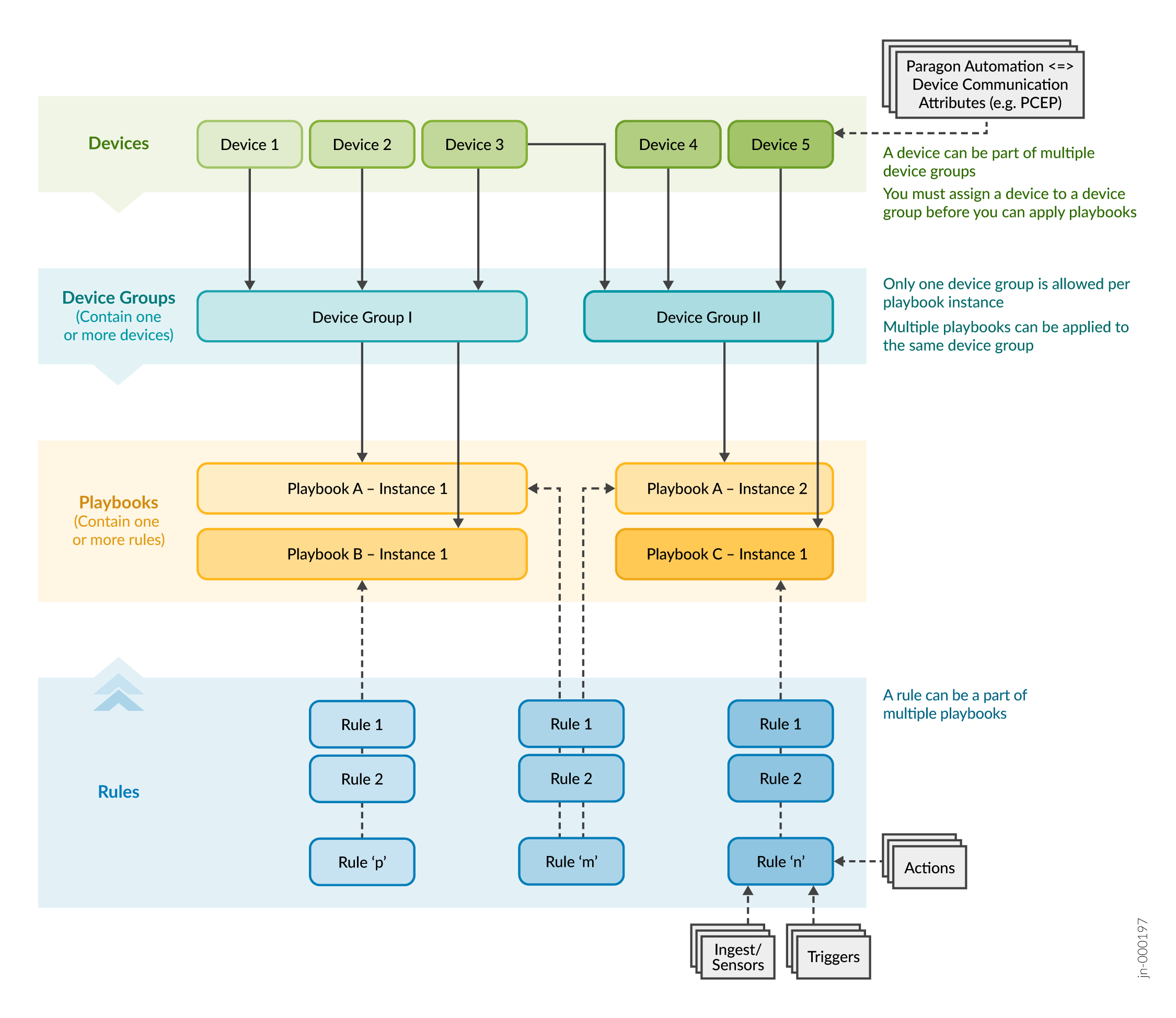
Figure 1 provides a high-level overview of the following concepts in Paragon Insights:
- How devices and device groups are related.
- How rules and playbooks are related.
- How devices and device groups, and rules and playbooks are associated with each other.
For more information, see the chapters on Playbooks and Rules in the Paragon Automation User Guide.
To get started with Paragon Insights:
- Configure the devices that you're monitoring using Paragon Insights to stream telemetry data. For details, see Network Device Requirements.
- Add the devices to a device group:
- On the Device Group Configuration page (Configuration >
Device Groups), click the Add (+)
icon.
The Add Device Group page appears.
- Configure the fields to add a device group, and include the devices that
Paragon Automation previously discovered to the device group.
For details, see Add a Device Group.
- On the Device Group Configuration page (Configuration >
Device Groups), click the Add (+)
icon.
- (Optional) Review the pre-existing rules and playbooks.
If required, you can:
- Upload predefined rules, predefined playbooks, or both. You can download predefined rules and playbooks from the Paragon Insights GitHub repository.
- Create rules, playbooks, or both.
For details, see the Playbooks and Rules chapters in the Paragon Automation User Guide.
- Apply one or more playbooks to the device group:
- On the Playbooks page (Configuration >
Playbooks), click the paper airplane icon corresponding
to the playbook that you want to apply.
The Run Playbook: Playbook-Name page appears.
- Enter the name of the playbook instance.
- Select the device group to which you want to apply the playbook.
- (Optional) Enter the variables.
- (Optional) Select the date and time schedule at which you want the playbook to run.
- Click Save & Deploy.
Paragon Insights runs the playbook instance, after a few seconds.
- Click the deployment status icon (on the Paragon Automation banner) to verify that the deployment was successful.
For more information, see Manage Playbook Instances.
- On the Playbooks page (Configuration >
Playbooks), click the paper airplane icon corresponding
to the playbook that you want to apply.
- After the playbook instances have finished running, access the Network Health page (Monitoring > Network Health), and select the device group for which you want to monitor the health.
Paragon Insights allows you to define entities called resources, which are used for root cause analysis (RCA) and for generating smart alerts. You can define resources at the network element level or at the network level. You can then configure resource properties, map a resource to Paragon Insights rules, and configure dependencies between resources. Paragon Insights then automatically identifies the resources that need to be discovered and maps the dependencies between the resource instances.
For details, see Understand Root Cause Analysis.
Configure Paragon Planner
Configure Paragon Planner to plan your network and simulate scenarios. You can use Paragon Planner features if you have installed the required license.
- If you haven't previously run a device collection task, which enables Pathfinder to obtain the configuration of network devices, run the task as explained in Step 2.
- Use Paragon Pathfinder to create an archive directly from the live network.
For details, see Add a Network Archive Task.
- Access the Paragon Planner Desktop
application:
- Ensure that the client PC from which you access the Paragon Planner
desktop application has the following installed:
- Java Runtime Environment (JRE): Depending on the operating system (OS) of the client PC, you must install a JRE or equivalent. For example, Azul Zulu (https://www.azul.com/downloads/?package=jdk) offers builds of Open Java Development Kit (OpenJDK) for both Windows and Mac OS.
- Web Start: You can use Open Web Start (https://openwebstart.com/) as a replacement for Java Web Start. Alternatively, you can use Iced Tea on Windows (https://adoptopenjdk.net/icedtea-web.html).
- Access the Paragon Planner desktop application by:
- Downloading the Java Network Launch Protocol (JNLP) file by using the Paragon Automation GUI.
- Using the JNLP file to launch the Paragon Planner desktop application.
- Logging in using your Paragon Planner credentials.
For details, see Access Paragon Planner Desktop Application.
- Ensure that the client PC from which you access the Paragon Planner
desktop application has the following installed:
- Open or import one of the archives and device collections created in Pathfinder to create a network model for Planner. For details, see Router Data Extraction Overview.
- Use the network model to run simulations in Paragon Planner.
For information about the tasks you can accomplish by using Paragon Planner, see the Paragon Planner Desktop Application User Guide.