Freeform Overview and Design
Freeform Reference Design Overview
A Freeform reference design differs from the other reference designs in that the network designer is responsible for creating and validating all device configurations. Any feature, protocol, or architecture that fits the deployment scenario can be leveraged. Devices and links are modelled in a topology editor, which creates objects representing the reference design in the graph database. As with the other reference designs, Freeform still leverages the context graph, Intent-Based Analytics (IBA), configuration validation, network operating system (NOS) management, Time Voyager, and numerous other Apstra software features. When compared to the more advanced reference designs however, reduced depth of IBA capabilities is the trade-off for greater design flexibility.
Freeform consists of various design and build elements and views that each manage specific network design aspects. Their function and usage are described in the following sections.
Blueprints
When creating a new network with Freeform reference design, you start by creating a Blueprint. As with the other reference designs, the Blueprint contains all elements associated with an operating network managed by Apstra, but there are a few key differences in how Blueprints are structured and used in Freeform.
The Data Center reference designs require design and build elements such as logical
devices, interface maps, racks, and templates. These steps are unnecessary in a Freeform
design because you create configuration details and device links directly into the
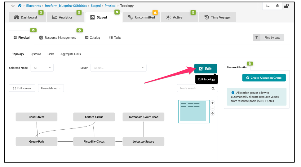
Blueprint. When creating a new Blueprint, you simply select the Freeform Reference Design,
as shown:
Blueprint Import/Export
You can import and export Freeform Blueprints into and out of Apstra. This allows you to simplify the migration of blueprints from one Apstra instance to another. This feature can also be utilized to create a “catalog” of Freeform reference designs. An engineer might use this catalog to standardize a network design by taking the information from the blueprint and implementing it as a standardized design for many Apstra implementations. These implementations could function as templates or models of a design that is used by an organization in multiple geographic locations, enabling fast, uniform deployments of custom network designs at scale. Another use case for this feature is the testing or evaluating of different network designs and systems. Examine various aspects of the imported/exported Blueprint without the commitment of a full deployment. All of these possibilities exist in Apstra Freeform.
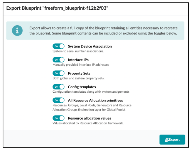
To Export a Blueprint follow this simple workflow:
You can then choose what elements of the Blueprint you would like to Export, as shown below. If all of the toggles are “off,” only the contents of the topology editor (discussed in the next section) are exported.
After the export is complete, the blueprint is saved in JSON format for use.
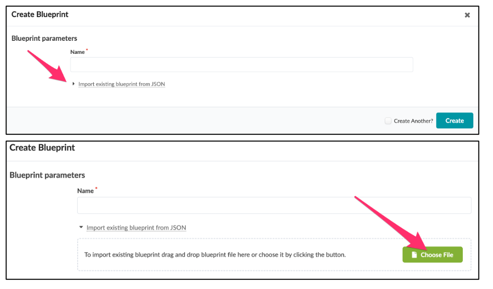
Importing a Blueprint is similar; simply create a new Blueprint and click on the import dialog, then select the Blueprint you want to import.
Topology
After creating a new Freeform Blueprint, you can begin designing your network topology. As
with the DC Reference Architectures, all design work is done from the Staged Blueprint tab.
The Staged topology editor area in Freeform is where you interact with the elements to
create your network design and architecture. The topology editor is a new capability in
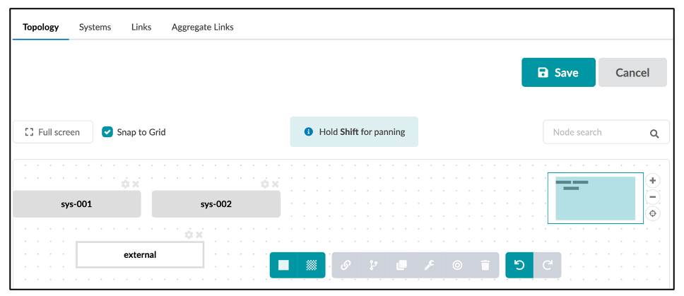
Freeform that allows you to create bespoke network designs in an interactive manner. You can
select networking devices and connect them interactively by defining links between them.
These devices can be internal or external.
Internal devices are managed by Apstra and must be mapped to device profiles that model device capabilities and interact with devices using agents. External devices are not directly under the Apstra management umbrella, but can still be modelled in the topology view in order to simulate interactions with internal devices. For example, you can simulate interface links and speeds. External devices do not utilize device agents or models.
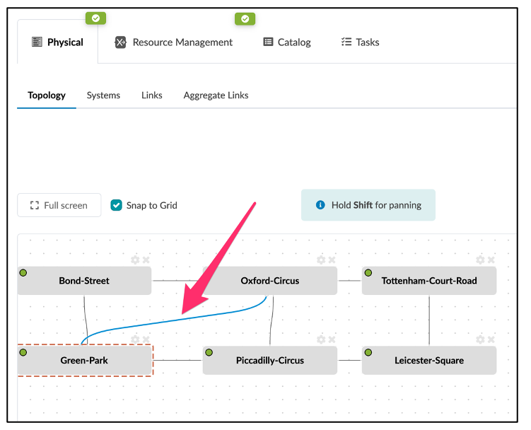
You can create single, multiple, or even aggregated links between devices. You can interact with the topology to re-arrange the design layout, add links, and edit colors or tags for devices and links. You can perform Create, Read, Update, and Delete (CRUD) operations by selecting the system's gear icon. You have the option to perform CRUD operations for both individual objects and objects in bulk.
Colors
You can use colors to create quick visual groupings and distinction between Apstra devices. For example, devices connecting to firewalls can be red while devices doing IP-Forwarding only can be orange.
Tags
In Apstra, Tags are a powerful feature. Tags are a way for you to assign metadata to Apstra-managed resources. These Tags can help you identify, organize, search for, and filter Apstra resources. Tags are also useful to help you categorize resources by purpose, owner, environment, or other criteria. Because Tags are metadata, they are not just used for visual labeling, but also applied as a property of the node in the Apstra graph database. This node property, or device property, is then available for you to reference in Jinja for dynamic variables in config generation and the Apstra real-time analytics via Apstra's Live Query technology and Apstra Intent-Based Analytics.
For example, you can use tag `firewall` to output a specific
description:
{% if has_tag(interface.link.neighbor_system.id, 'firewall') %}
   description "this is a firewall facing interface";
{% endif %}
For more examples of how to access and use tags, see the Accessing Values in The Device Context and Jinja Support sections.
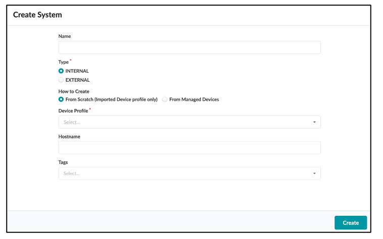
Creating Systems
There are two ways to create a new System:
1. Navigate to Staged > Topology > Topology Editor.
Use the first two icons in the bottom menu to create either an internal or an external system. The new system will appear in the topology view. When creating an internal system, you can optionally specify which Device Profile to use and assign a System ID. See how to create and import Device Profiles into the Blueprint in the Device Profiles section.
2. Navigate to Staged > Systems.
This method automatically adds the new systems in the Topology view.
You can choose to create a new system from an existing managed device or create a new system with a specific device profile and assign a managed device later once the equipment is ready and part of the Apstra managed devices.
Creating Links
You can use links to connect objects or devices together. Links are single or aggregate links. These links can have parameters assigned to them via the topology editor "gear" icon. The links can have IP addresses and tags assigned.
Link Aggregations (LAGs)
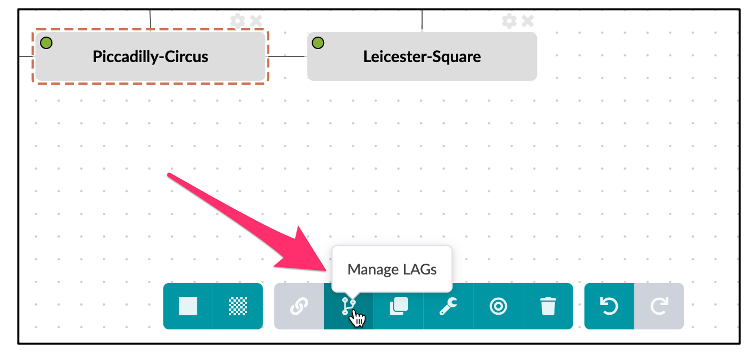
Links can be a Link Aggregation, or LAG. Access the LAG editing area by selecting the Topology view, then selecting a device, then selecting the Manage LAGs icon.
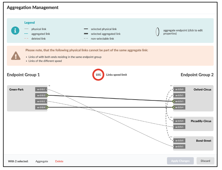
The following is a view of the Link aggregation user interface.
Select two links to form an aggregate. The changes display after clicking
Aggregate.
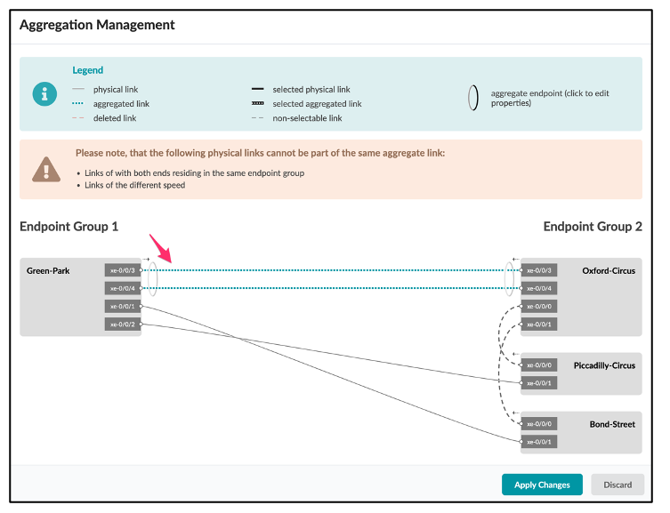
Click Apply Changes to update the topology editor with the new LAG. The aggregate link is thicker and colored blue.
Link & LAG management simplifies the potentially complex process of managing the different permutations of link setups.
Device Profiles
Device Profiles define the capabilities of supported hardware devices. Some feature capabilities have different behaviors across NOS versions. Certain capabailties might perform differently depending on your NOS version.
In the initial versions of Freeform, only Device Profiles for Juniper Networks devices are supported.
Before you can create a Blueprint, you must import Device Profiles into the Blueprint. You can then use those devices in the topology editor of the Blueprint.
Execute CLI Commands
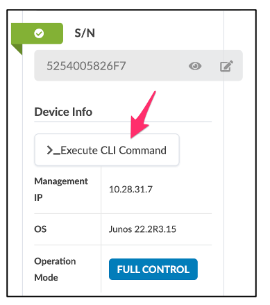
Users might want to interact with the devices in your network directly via CLI for functions like statistics display, or to check device status or interface health. Apstra Freeform simplifies CLI access. Considering the range of devices that might make up a network, this feature is more useful than ever in custom Freeform topologies. To access the CLI command functionality, navigate to the device and you will see the following dialog:
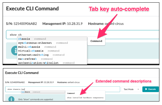
Click on the Execute CLI Command field. A CLI field displays for CLI commands. Typing part of a command displays a prompt containing all available related commands within the CLI structure.
Only show commands are currently supported.
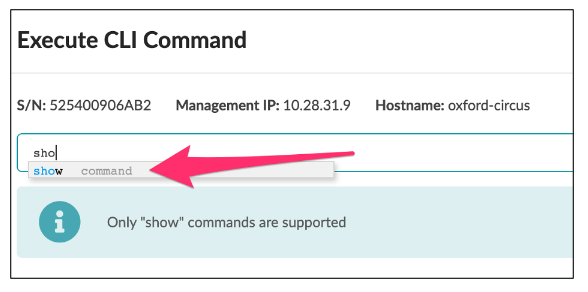
Use the Tab key to auto-complete your command to the next hierarchical level.
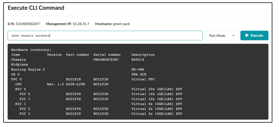
The following is an example output from the CLI command. You don't have to open a terminal session and SSH into the device to view outputs. Aside from the text output in this example, you can also select XML or JSON output formats.
Config Templates
Since the design of the network elements in Freeform is arbitrary, the device configurations are not automatically rendered by the Freeform reference design; rather, you have complete control of the configuration of your devices.
Beginning in Apstra 4.1.1, we introduce the concept of a Config Template specifically for Freeform to drive device configuration. Config Templates can be very simple and static to very complex and programmatic, depending on the use case and level of automation you are comfortable with. Config Templates support using Jinja2 template language, which can optionally interact with the device context and property sets.
Nesting (Composable) Config Templates
As Config Templates support Jinja templating, a powerful nesting feature is supported that enables you to include a section of a config template from the list inside of another config template. There are two main benefits of nesting config templates. The first is that with nesting, you can separate various services, configuration sections, etc. out to common components and create dedicated config templates for them.
For example, assume that you have a base system stanza configuration for banners, logins, NTP, etc., for most of your Juniper devices. Instead of copying and pasting the same configuration into each of your device templates, you can create a dedicated config template for the base system config. Then, simply reference that template from within another template.
The second benefit is that you only need to link one config template to a device. That device automatically inherits all configuration settings of any linked templates.
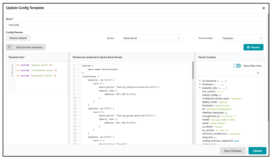
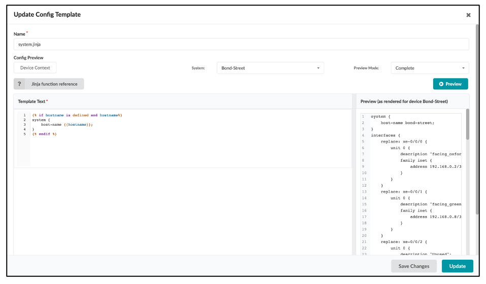
As an example, the
following config template, junos_configuration.jinja, is a single config
template with several nested config templates, such as junos_system.jinja
and junos_interfaces.jinja. You only need to link the
junos_configuration_jinja template to device bond-street
and all nested config templates are applied.
In the
following image, the junos_system.jinja only renders the system hostname
(bond-street) of it's parent template:
Rendering Order
Apstra renders the configuration according to the order of the config template.
Property Sets
Property sets are collections of key-value pairs that you import into Blueprint catalogs to use in Config Templates and IBA probes. The use of property sets is optional, but it provides a valuable capability that allows you to fully parameterize Config Templates by separating the persistent settings of the Config Template from the actual variables. In other words, property sets enable a more granular control of the Device Model used to render configurations arbitrarily and flexibly.
For example, the configuration of NTP on all devices in the enterprise may be consistent, but with differing time sources or strata per geography. You can create an NTP config template using a different variable for each geographic location. For example, you can use the property named "ntp".
It’s important to use the correct syntax, and remember that key values are case sensitive.
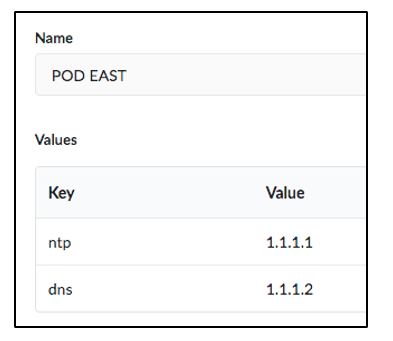
In this case you can create the Config Template with {{ntp}} instead of the IP address of NTP server. This Config Template is imported into all Blueprints, but Blueprints running in the East region have the “EAST” property set imported, and Blueprints running in the West region have the “ WEST” property set imported. Property sets are globally scoped by default.
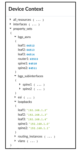
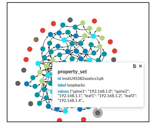
Freeform also supports property sets that are assigned to a specific device. This enables you to create specific property sets and assign them to certain devices. Apstra stores property sets in a graph database where their values can be used in IBA probes.
The following examples show that you can access property sets via the Device Context tab or the Graph visualizer.
Data Structures in Property Sets
Freeform property sets support advanced data structures that you can use to fulfill different use cases. Freeform Property Sets support any of the typical Python data types, including:
- Arrays (list of items)
- Boolean: True or False
- Integers: 1, 2, 3 etc.
- Float: 1.2, 3.65, etc.
- String: “Hello World”
- Dictionary: {“asn”: 65432, “lo0”: “1.2.3.4/32”}
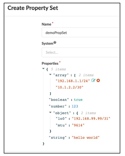
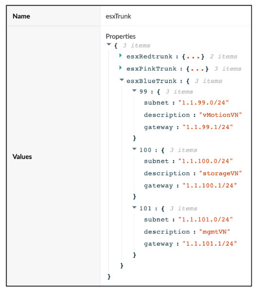
You can reference the Property Set globally or assign it to a System in the Blueprint.
In the example above, you can recurse the dictionary using the keys and use the keys as values as required:
- esxRedTrunk is the link tag name to be used as an interface description
- 99, 100, 101 are the VLAN ID / trunk members & irb.<value> to be assigned
- subnet / description / gateway are also used to derive meaningful configuration


