Interface Maps Introduction
Interface maps consist of interfaces used for achieving the intended network configuration rendering. They map interfaces between logical devices and physical hardware devices (represented with device profiles) while adhering to vendor specifications.
Some characteristics and capabilities of interface maps include:
- Precisely select device ports, transformations and interfaces.
- You are not restricted to selecting interfaces in a contiguous manner.
- Provision QSFP+ breakout ports to transform ports, such 40GbE ports to 10GbE, 100GbE ports to 25GbE, and so on.
- Port breakouts and available speeds affect possible values of the mapping fields.
- The logical device enables you to plan port and panel mappings accordingly. For example, you can assign a network policy that ensures that spine uplink ports on a leaf switch are always the furthest right ports on a panel.
- If a smaller logical device is mapped to a larger physical device, the unmapped ports in the device profile are marked as Unused in the interface map.
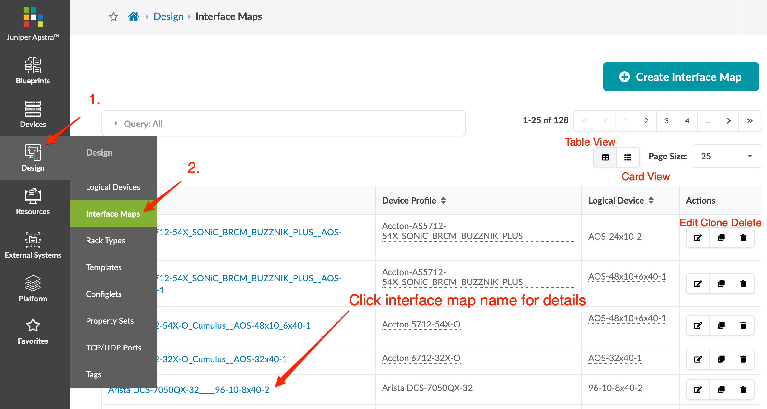
From the left navigation menu, navigate to Design > Interface Maps
to go to interface maps in the global catalog. You can create, clone, edit and delete
interface maps. 
Click an interface map name to go to its details. 
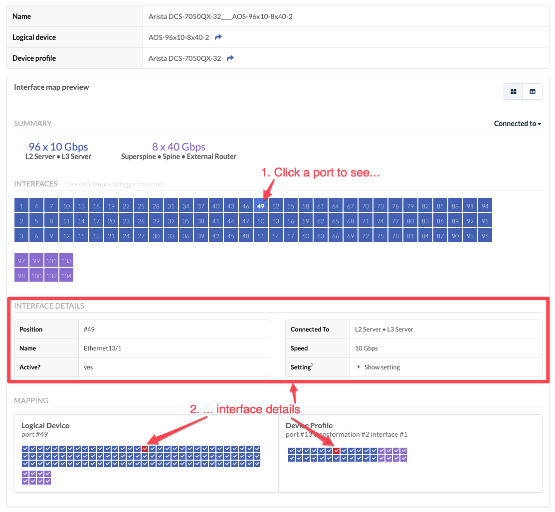
Click a port to go to interface details. Interface maps include the following details:
| Logical Device |
Abstraction of the physical device. |
| Device Profile |
Physical device characteristics. |
| Interfaces |
Mapping between logical devices and physical devices (device profile) |
