Topology (Freeform)
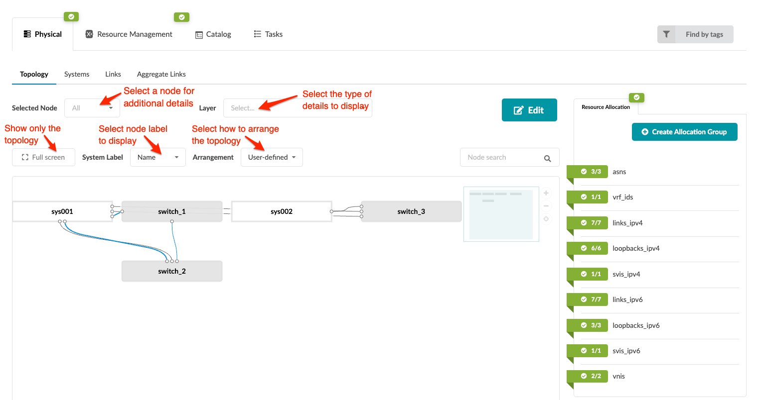
The Topology view shows in a graphical way the collection of devices/objects that make up the network and the links that connect devices. It self-documents your intended network state. This is then modeled/created in the Apstra GraphDB for intent-based modeling. You can perform various tasks from the Topology view, via the topology editor, as described in later sections.
To go to the topology view from the blueprint, navigate to Staged > Physical > Topology.

You can display topology information in various ways:
-
To focus on just the topology without showing all the other tabs, view it in full screen mode.
-
To select which label to display on system nodes, select it from the System Label drop-down list (new in Apstra version 4.2.0):
-
Name
-
Hostname
-
Serial Number (system ID)
-
IP address
-
-
Select how the elements are arranged by selecting an arrangement from the Arrangement drop-down list:
-
User-defined
-
Layered
-
Stress
-
Force
-
Compaction
-
-
To display a specific layer, select it from the Layer drop-down list:
-
Config Template Assignments - Assigned, Not Assigned
-
Deploy Mode - Deploy, Ready, Drain, Undeploy
-
Operation Mode - Full Control, Telemetry Only
-
System ID Assignements - Assigned, Not Assigned
-
Uncommitted Changes - Has Uncommitted Changes or not
-
-
Select a node from the Selected Node drop-down list to go to the Systems detail page.
