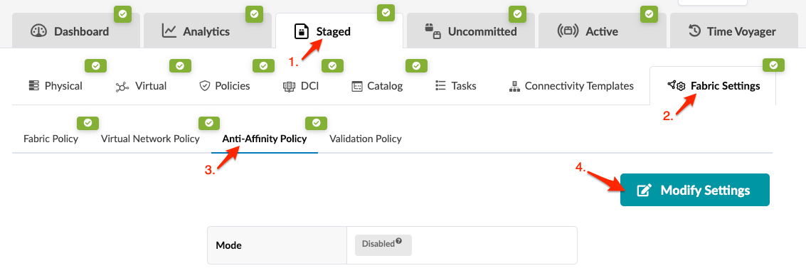
Anti-Affinity Policy
Anti-Affinity Policy Overview
When designing high availability (HA) systems, you want parallel links between two devices to terminate on different physical ports, thus avoiding transceiver failures from impacting both links on a device. Depending on the number of interfaces on a system, manually modifying these links could be time-consuming. With the anti-affinity policy (new in Apstra version 4.0.1) you can apply certain constraints to the cabling map to control automatic port assignments. When you enable the policy, you can specify the maximum number of links as follows:
- Max Links Count per Slot - maximum total number of links connected to ports/interfaces of the specified slot regardless of the system they are targeted to. It controls how many links can be connected to one slot of one system. Example: A line card slot in a chassis.
- Max Links Count per System per Slot - restricts the number of links to a certain system connected to the ports/interfaces in a specific slot. It controls how many links can be connected to one system to one slot of another system.
- Max Links Count per Port - maximum total number of links connected to the interfaces of the specific port regardless of the system they are targeted to. It controls how many links can be connected to one port in one system. Example: Several transformations of one port. In this case, it controls how many transformations can be used in links.
- Max Link Count per System per Port - restricts the number of interfaces on a port used to connect to a certain system. It controls how many links can be connected from one system to one port of another system. This is the one that you will most likely use, for port breakouts.
The anti-affinity policy has three modes:
- Disabled (default) - ports selection is based on assigned interface maps and interface names (provided or auto-assigned). Port breakouts could terminate on the same physical ports.
- Enabled (loose) - controls interface names that were not defined by the user. Does not control or override user-defined cabling. (If you haven't explicitly assigned any interface names, loose and strict are effectively the same policy.)
- Enabled (strict) - completely controls port distribution and could override user-defined assignments. When you enable the strict policy, a statement appears at the top of the cabling map (Staged/Active > Physical > Links and Staged/Active > Physical > Topology Selection) stating that the anti-affinity policy is enabled ("forced" for strict).
An example of when you'd want to apply the anti-affinity policy is when you have a QSFP 40G breakout port that you want to break out into 4-10G ports. You can ensure that any links that go to the same device use different QSFP ports instead of 2-10G spine links on the same QSFP port. This gives you an added layer of redundancy if that QSFP port fails.
Enable/Disable Anti-Affinity Policy
Every time you change the policy, port assignments are recalculated.
When you're ready to activate your changes, commit them from the Uncommitted tab.

