- play_arrow Getting Started
- play_arrow Blueprints
- play_arrow Blueprint Analytics
- What are Blueprint Analytics
- play_arrow Dashboards
- What are Blueprint Analytics Dashboards
- Configure Auto-Enabled Blueprint Analytics Dashboards
- Instantiate Predefined Blueprint Analytics Dashboard
- Create Blueprint Analytics Dashboard
- Export Blueprint Analytics Dashboard
- Import Blueprint Analytics Dashboard
- Update Blueprint Analytics Dashboard
- Delete Blueprint Analytics Dashboard
- play_arrow Anomalies
- play_arrow Probes
- play_arrow Predefined Reports
- play_arrow Root Causes
- play_arrow Staged Freeform Blueprints
- Freeform Introduction
- play_arrow Blueprints
- play_arrow Physical
- play_arrow Selection
- play_arrow Topology
- play_arrow Systems
- Systems Introduction (Freeform)
- Create Internal System (Freeform)
- Create External System (Freeform)
- Update Assigned Config Template(Freeform)
- Update System Name (Freeform)
- Update Hostname (Freeform)
- Change Assigned Device Profile (Freeform)
- Update System ID Assignment (Freeform)
- Update Deploy Mode (Freeform)
- Add / Remove Tags on System (Freeform)
- Delete System (Freeform)
- Device Context (Freeform)
- play_arrow Links
-
- play_arrow Resource Management
- Resource Management Introduction (Freeform)
- play_arrow Blueprint Resources
- play_arrow Allocation Groups
- play_arrow Local Pools
- play_arrow Catalog (Freeform)
- play_arrow Config Templates
- play_arrow Device Profiles
- play_arrow Property Sets
- play_arrow Tags
-
- play_arrow Tasks
- play_arrow Uncommitted Blueprints
- play_arrow Active Datacenter Blueprints
- play_arrow Time Voyager (Blueprints)
- play_arrow Devices
- Device Configuration Lifecycle
- What are Managed Devices
- Add Managed Device
- Drain Device Traffic
- Upgrade Device NOS
- Device AAA
- play_arrow Device
- play_arrow Agent
- play_arrow Pristine Config
- play_arrow Telemetry
- play_arrow Apstra ZTP
- What is Apstra ZTP
- Create User Profile for Communicating with ZTP Server
- Download and Deploy Apstra ZTP Server VM
- Configure Static Management IP Address for Apstra ZTP Server
- Replace SSL Certificate for Apstra ZTP Server GUI
- Create Vendor-specific Custom Configuration
- Configure Credentials for Apstra ZTP Server GUI
- Configure Apstra Server Connection Details
- Configure DHCP Server for Apstra ZTP
- ztp.json Keys
- Configure ztp.json with Configurator
- Configure ztp.json with CLI
- Show Apstra ZTP Logs
- Onboard Devices with Apstra ZTP
- Check ZTP Status of Devices and Services
- Reset Apstra ZTP GUI Admin Password
- Authenticate User (AZTP REST API)
- play_arrow Device Profiles
- play_arrow Design
- play_arrow Logical Devices
- play_arrow Interface Maps
- play_arrow Rack Types
- play_arrow Templates
- play_arrow Config Templates (Freeform)
- play_arrow Configlets (Datacenter)
- play_arrow Property Sets (Datacenter)
- play_arrow TCP/UDP Ports
- play_arrow Tags
-
- play_arrow Resources
- play_arrow Analytics - Telemetry
- play_arrow Analytics - Flow
- play_arrow Apstra Flow Overview
- play_arrow Dashboards
- play_arrow Supported Flow Records
- play_arrow Flow Enrichment
- play_arrow Monitor Apstra Flow
- play_arrow Configuration Reference
- play_arrow API
- play_arrow Additional Documentation
- play_arrow Knowledge Base
-
- play_arrow Analytics - Exploratory Analytics
- play_arrow External Systems (RBAC Providers)
- play_arrow Providers
- play_arrow Provider Role Mapping
-
- play_arrow Platform
- play_arrow User Management
- play_arrow Security
- play_arrow External Services
- play_arrow Streaming
- Event Log (Audit Log)
- Licenses
- play_arrow Apstra VM Clusters
- play_arrow Developers
- play_arrow Technical Support
- Check Apstra Versions and Patent Numbers
-
- play_arrow Favorites & User
- play_arrow Apstra Server Management
- Apstra Server Introduction
- Monitor Apstra Server via CLI
- Restart Apstra Server
- Reset Apstra Server VM Password
- Reinstall Apstra Server
- Apstra Database Overview
- Back up Apstra Database
- Restore Apstra Database
- Reset Apstra Database
- Migrate Apstra Database
- Replace SSL Certificate on Apstra Server with Signed One
- Replace SSL Certificate on Apstra Server with Self-Signed One
- Change Apstra Server Hostname
- FIPS 140-2 Support
- play_arrow Apstra CLI Utility
- play_arrow Guides
- play_arrow References
- play_arrow Feature Matrix
- play_arrow Devices
- play_arrow Blueprint Analytics
- play_arrow Predefined Dashboards
- play_arrow Predefined Probes
- BGP Monitoring Probe
- Probe: Bandwidth Utilization
- Probe: Critical Services: Utilization, Trending, Alerting
- Probe: Device Environmental Checks
- Probe: Device System Health
- Probe: Device Telemetry Health
- Probe: Device Traffic
- Probe: Drain Traffic Anomaly
- Probe: ECMP Imbalance (External Interfaces)
- Probe: ECMP Imbalance (Fabric Interfaces)
- Probe: ECMP Imbalance (Spine to Superspine Interfaces)
- Probe: ESI Imbalance
- Probe: EVPN Host Flapping
- Probe: EVPN VXLAN Type-3 Route Validation
- Probe: EVPN VXLAN Type-5 Route Validation
- Probe: External Routes
- Probe: Hot/Cold Interface Counters (Fabric Interfaces)
- Probe: Hot/Cold Interface Counters (Specific Interfaces)
- Probe: Hot/Cold Interface Counters (Spine to Superspine Interfaces)
- Probe: Hypervisor and Fabric LAG Config Mismatch Probe (Virtual Infra)
- Hypervisor and Fabric VLAN Config Mismatch Probe
- Probe: Hypervisor MTU Mismatch Probe (Virtual Infra - NSX-T Only)
- Probe: Hypervisor MTU Threshold Check Probe (Virtual Infra)
- Probe: Hypervisor Missing LLDP Config Probe (Virtual Infra)
- Probe: Hypervisor Redundancy Checks Probe (Virtual Infra)
- Probe: Interface Flapping (Fabric Interfaces)
- Probe: Interface Flapping (Specific Interfaces)
- Probe: Interface Policy 802.1x
- Probe: LAG Imbalance
- Probe: Leafs Hosting Critical Services: Utilization, Trending, Alerting
- Probe: Link Fault Tolerance in Leaf and Access LAGs
- Probe: MAC Monitor
- Probe: MLAG Imbalance
- Probe: Multiagent Detector
- Probe: Optical Transceivers
- Probe: Packet Discard Percentage
- Probe: Spine Fault Tolerance
- Probe: Total East/West Traffic
- Probe: VMs without Fabric Configured VLANs Probe (Virtual Infra)
- Probe: VXLAN Flood List Validation
- play_arrow Probe Processors
- Processor: Accumulate
- Processor: Average
- Processor: BGP Session
- Processor: Comparison
- Processor: Environment
- Processor: EVPN Type 3
- Processor: EVPN Type 5
- Processor: Extensible Service Collector
- Processor: Generic Graph Collector
- Processor: Generic Service Data Collector
- Processor: Interface Counters
- Processor: Logical Operator
- Processor: MAC
- Processor: Match Count
- Processor: Match Percentage
- Processor: Match String
- Processor: Max
- Processor: Min
- Processor: Optical Threshold
- Processor: Optical Xcvr
- Processor: Periodic Average
- Processor: Periodic Change
- Processor: Range
- Processor: Ratio
- Processor: Service Collector
- Processor: Set Comparison
- Processor: Set Count
- Processor: Standard Deviation
- Processor: State
- Processor: Subtract
- Processor: Sum
- Processor: System Utilization
- Processor: Telemetry Service Health
- Processor: Time in State
- Processor: Traffic Monitor
- Processor: Union
- Processor: VXLAN Floodlist
- Configlet Examples (Design)
- Apstra EVPN Support Addendum
- Apstra Server Configuration File
- Graph
- Juniper Apstra Tech Previews
-
NSX-T Edge and Connectivity Templates
Overview
Juniper Apstra supports NSX-T Edge connectivity requirements using connectivity templates. Connectivity templates can be used both where NSX-T Edge is hosted on Bare Metal or when used as a virtual machine.
We support VRF lite enabled Tier-0 edge Gateway using connectivity templates.
The use cases below relate to connectivity templates for NSX-T 3.0 Edge:
Set Up NSX-T Tier-0 Router BGP peering
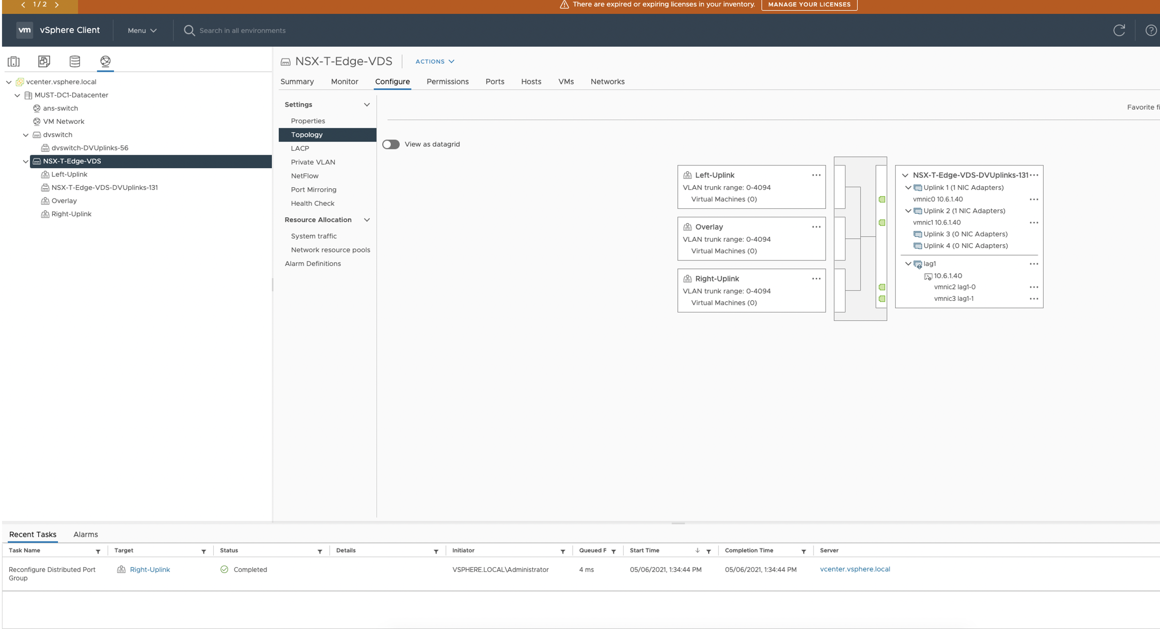
Let's say NSX-T Edge VM uplinks are connected to ToR leaf devices via VLAN Transport
Zone which provides uplink network connectivity to physical infrastructure. Then
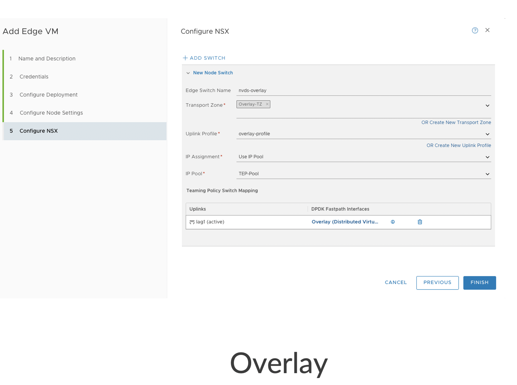
Edge VM will also have vmnics as per below screenshot which will help for tunnelling
traffic between Transport Nodes. This is called Overlay Transport Zone.
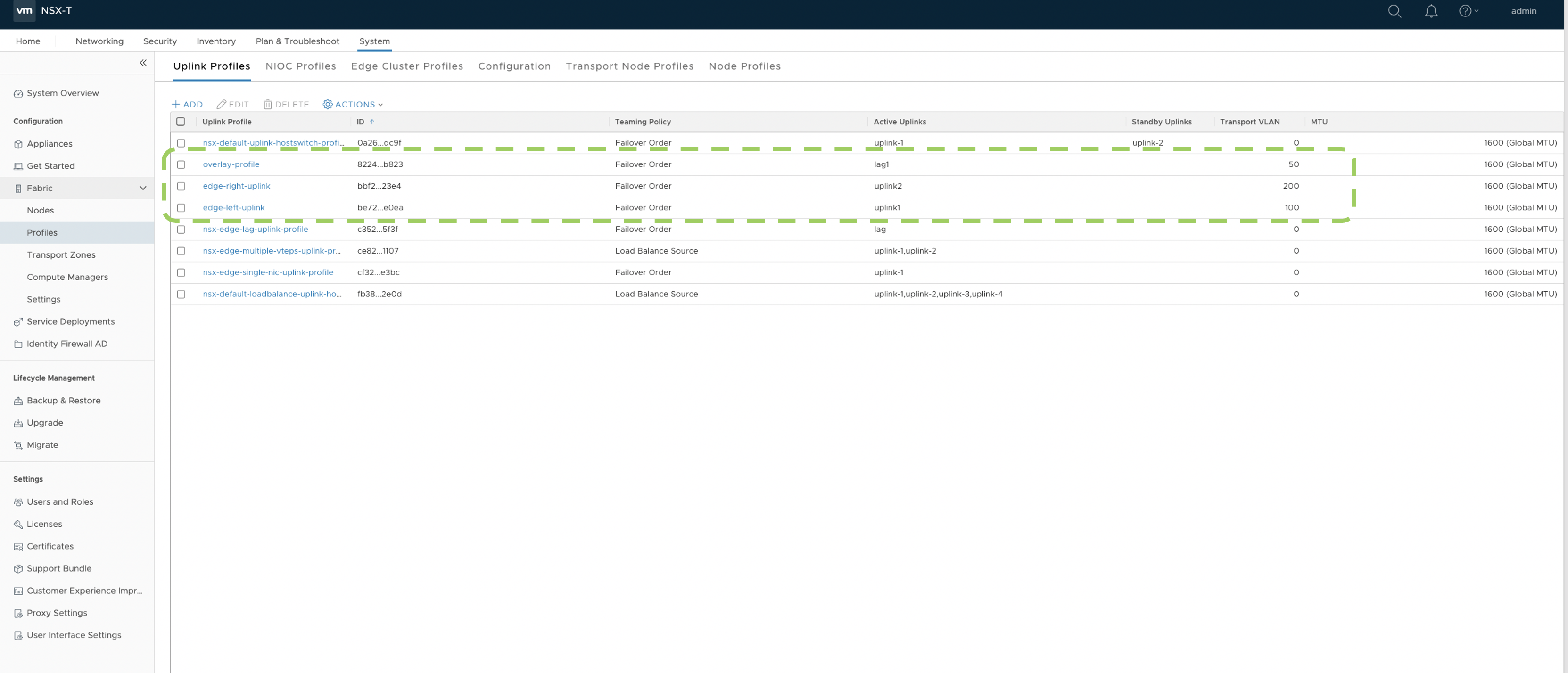
Create three Distributed Port Groups for respective vmnics and VLAN Trunking to be enabled on all the Nodes as per the networking depicted in previous screenshot.
- Create respective Uplink profiles for Overlay and VLAN Transport Zones in NSX
Manager(UI).
- After NSX-T is configured on the Transport nodes, a Tunnel endpoint(TEP) IP pool
is created in the NSX UI as below:
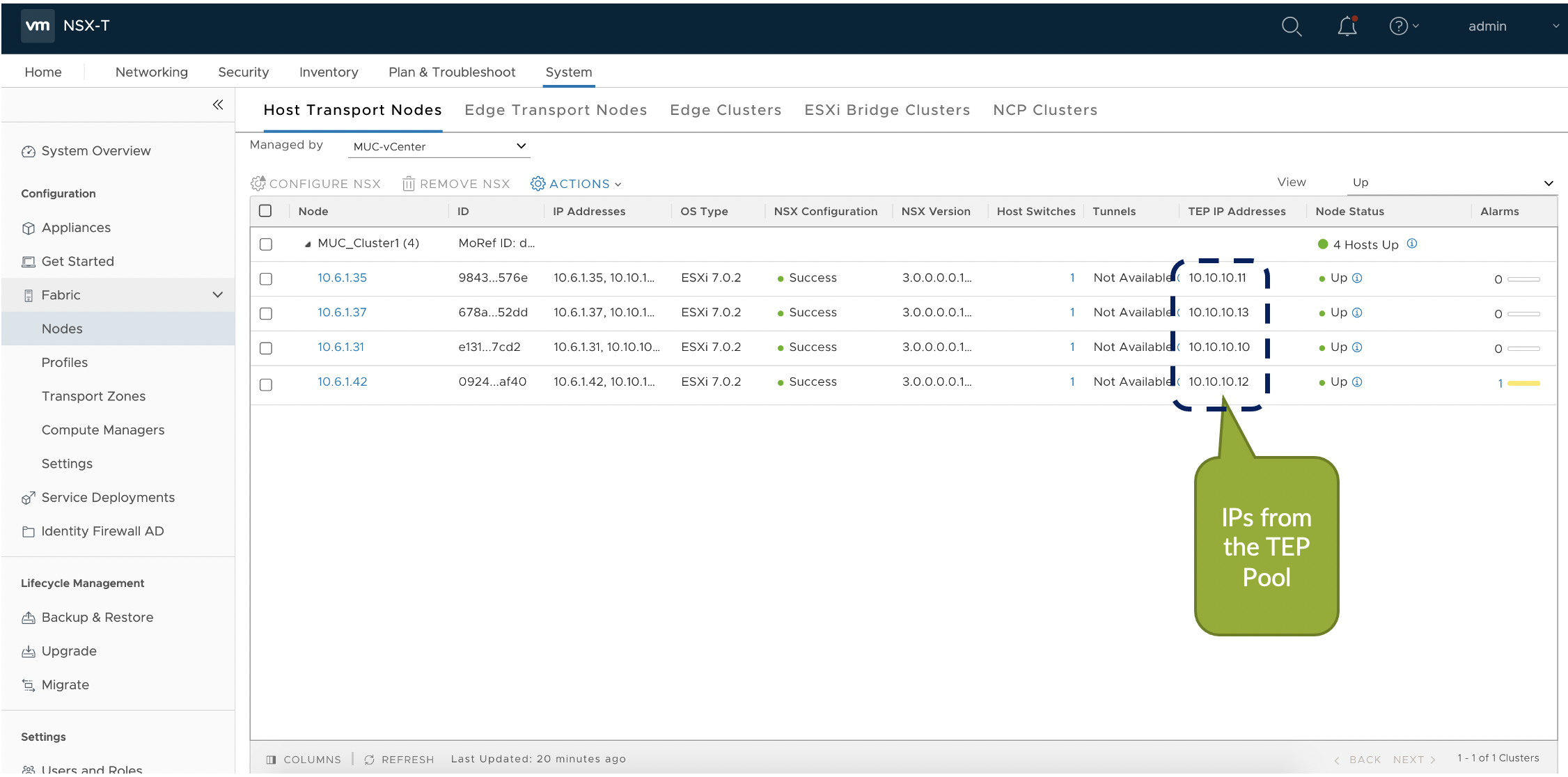
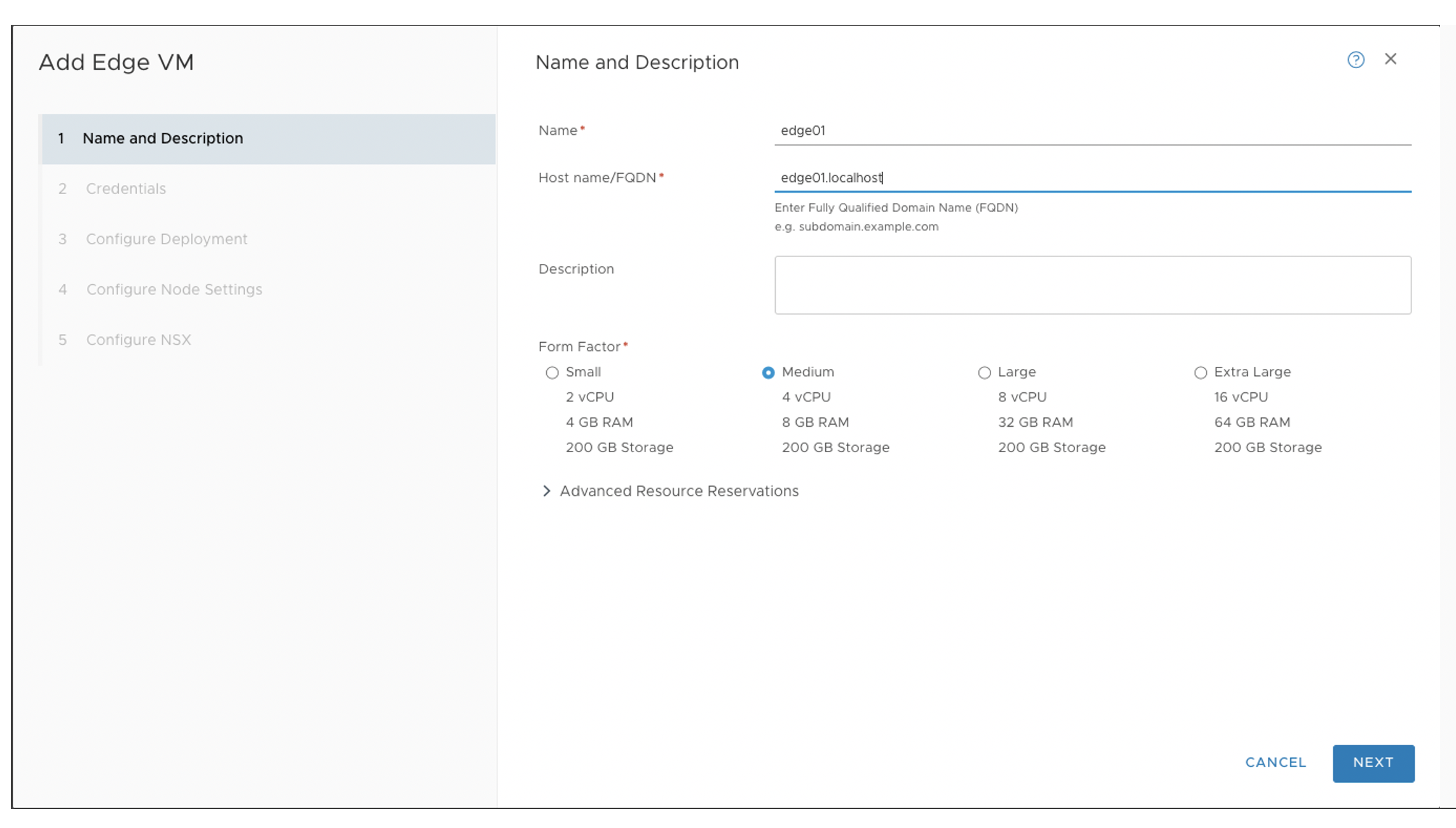
- Now create the NSX-T Edge VM in NSX Manager UI as below. It is used as the
device for north-south communication and BGP peering with Juniper Apstra Fabric.
Also configure VDS on the Edge Nodes under NSX Manager(UI) for respective
overlay and Uplink interfaces.
Tier-0 Gateway in the NSX-T Edge cluster provides a gateway service between the logical and physical network. In NSX Manager create T0 Gateway which connects to the ToR Leaf via BGP to communicate with the rest of Juniper Apstra Fabric.
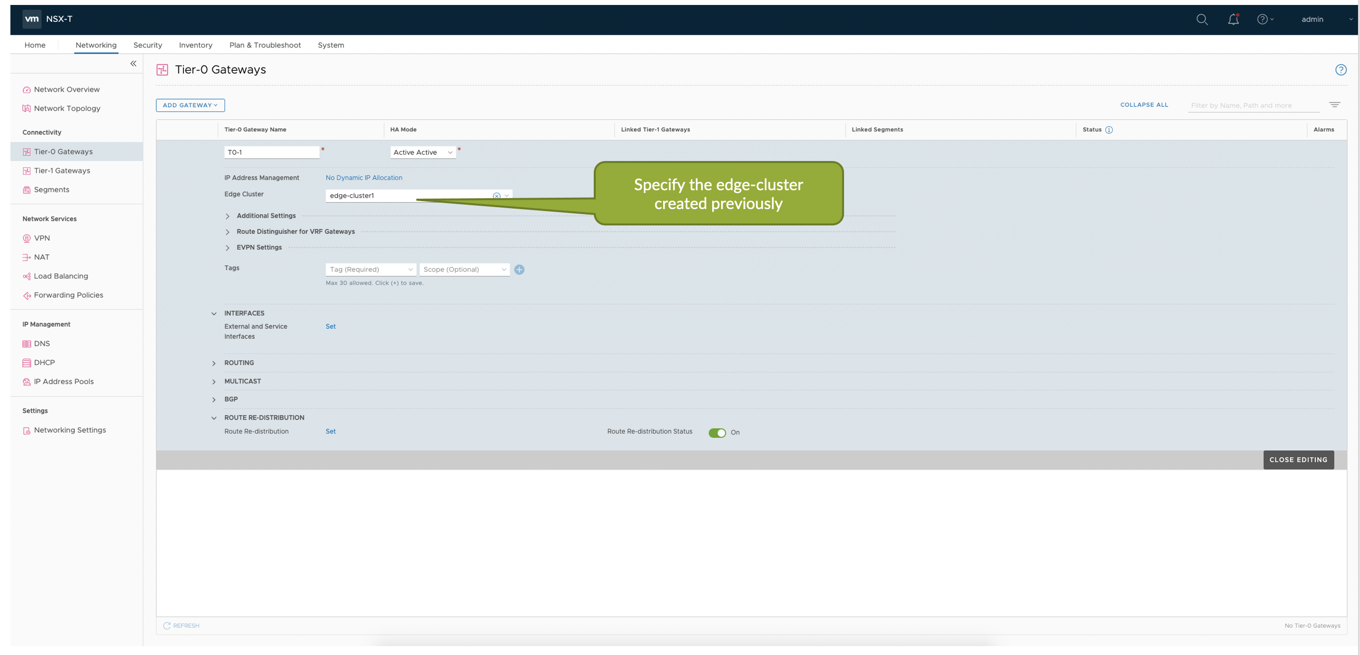
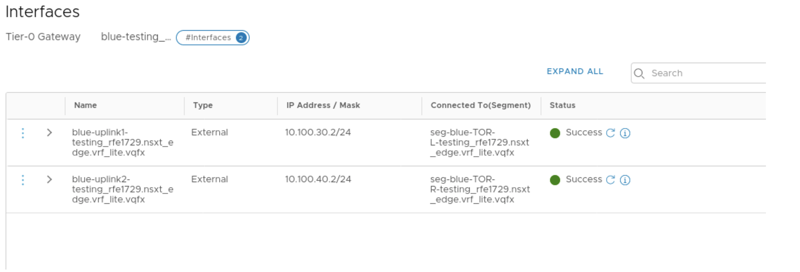
- Add External interfaces to the T0 GW which maps to the Uplink segments
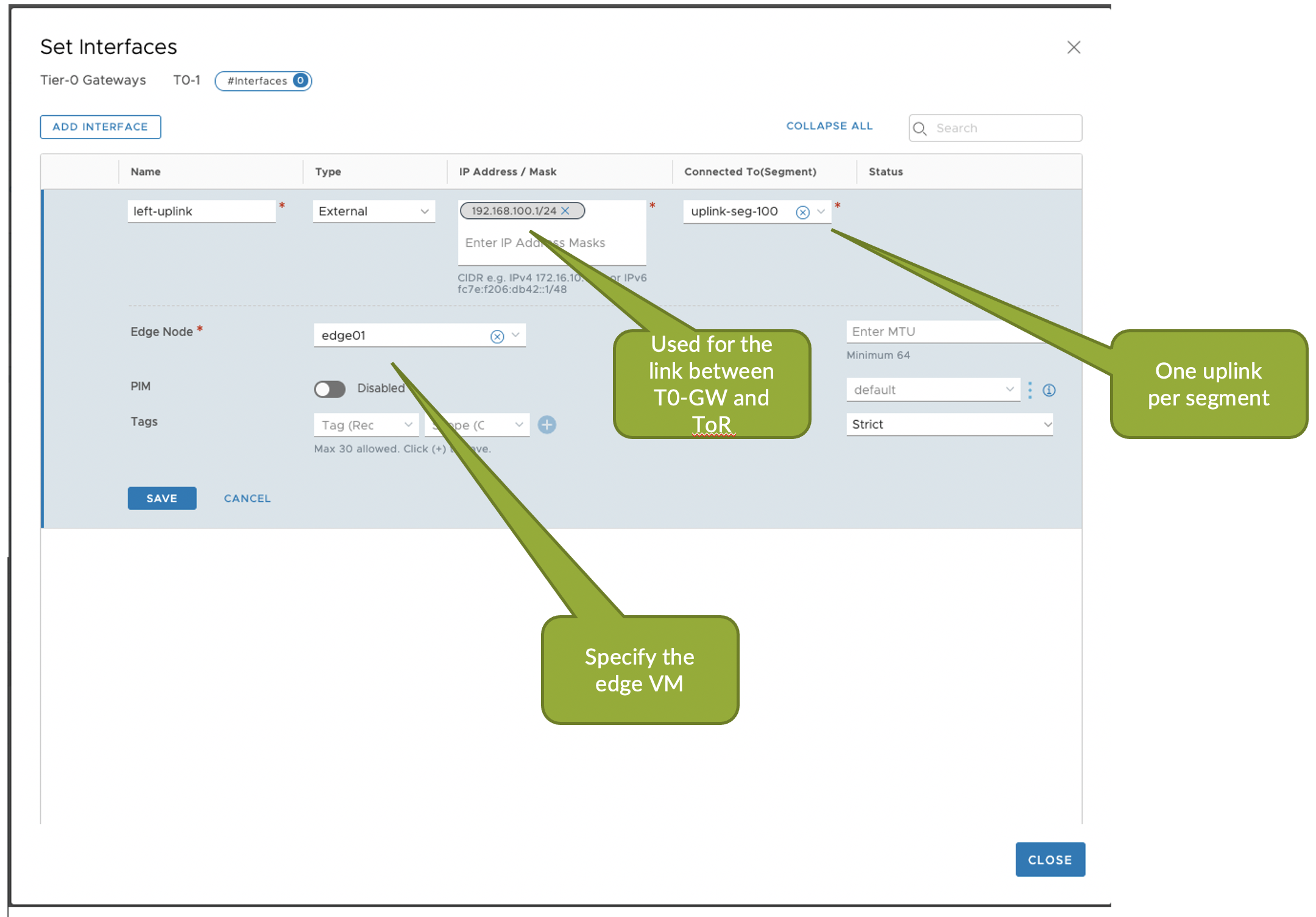
- Configure BGP peering on NSX T0 GW towards Juniper Apstra Fabric in NSX Manager.
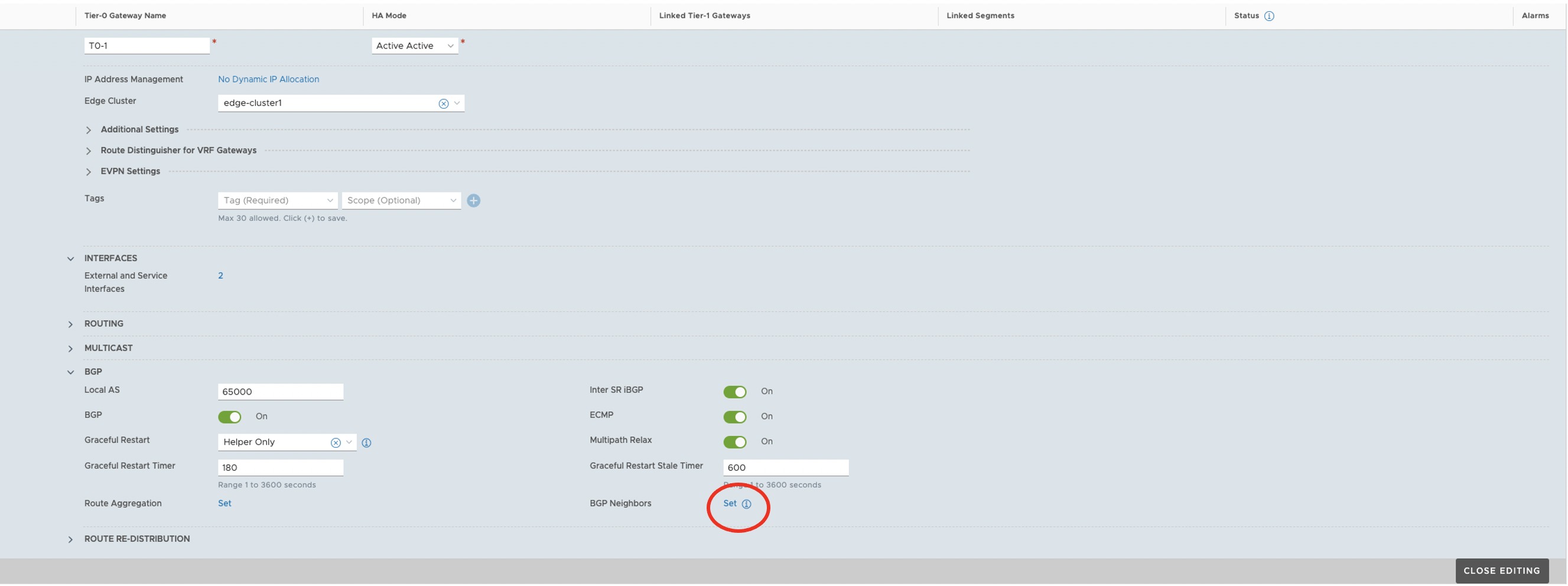
- For NSX-T integration with Juniper Apstra, see NSX-T Integration
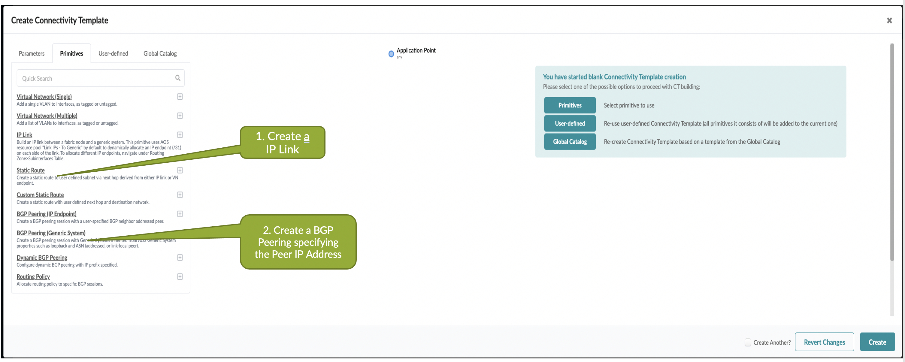
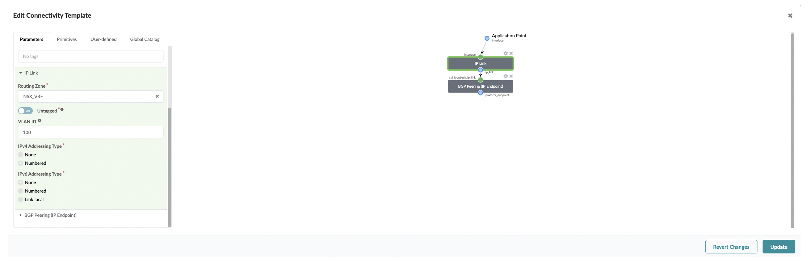
First create a Routing Zone in Juniper Apstra UI which maps to a VRF. Then need to setup IP Link Primitive based connectivity template to establish BGP peering from the NSX-T Edge node to Fabric as below:
Specify the routing zone on which the IP link will be added and respective VLAN ID.
Set Up NSX-T VRF Lite
With NSX-T VRF Lite we are able to configure per tenant data isolation. Each VLAN can be considered as a separate channel for data plane under VRF gateways.
BGP peering can be built over these VLANs in VRF gateways for route exchange with the upstream Juniper Apstra fabric. Inter-VRF traffic is routed through the physical Juniper Apstra fabric.
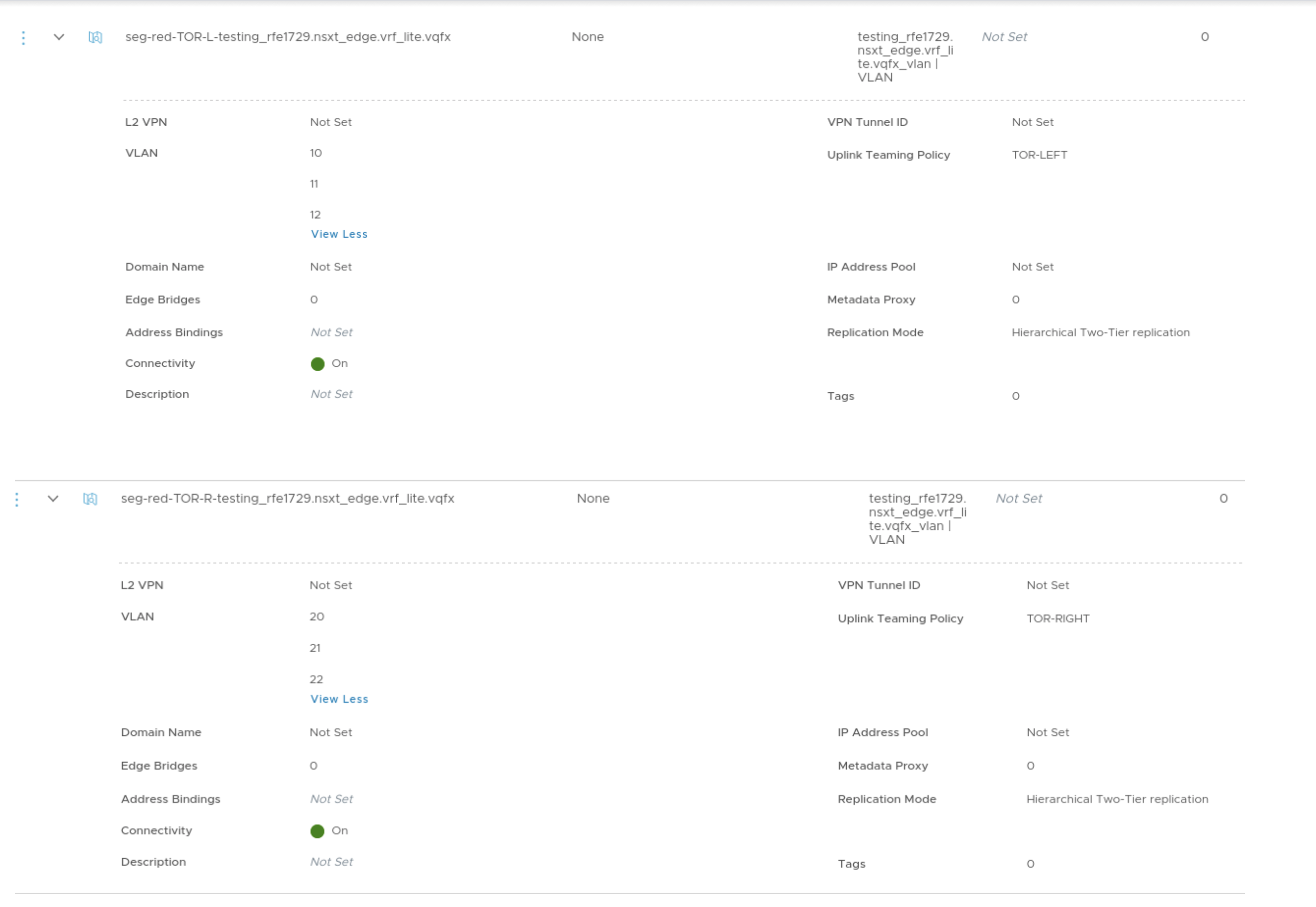
- In NSX-T Manager create the VLAN Segments for the Uplink networks for the
tenants.
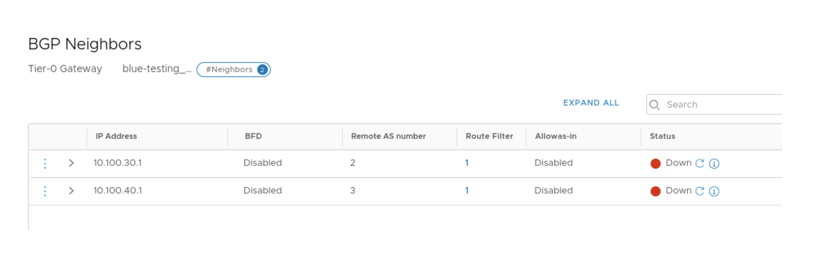
- In NSX-T Manager create the VRF-enabled Tier-0 Gateway for the tenants and add
the uplink interfaces on the VRF enabled Gateways. Thereafter add the BGP
neighbors.
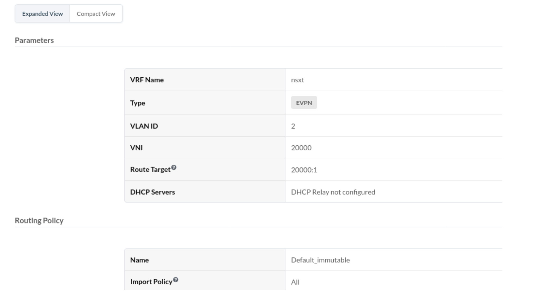
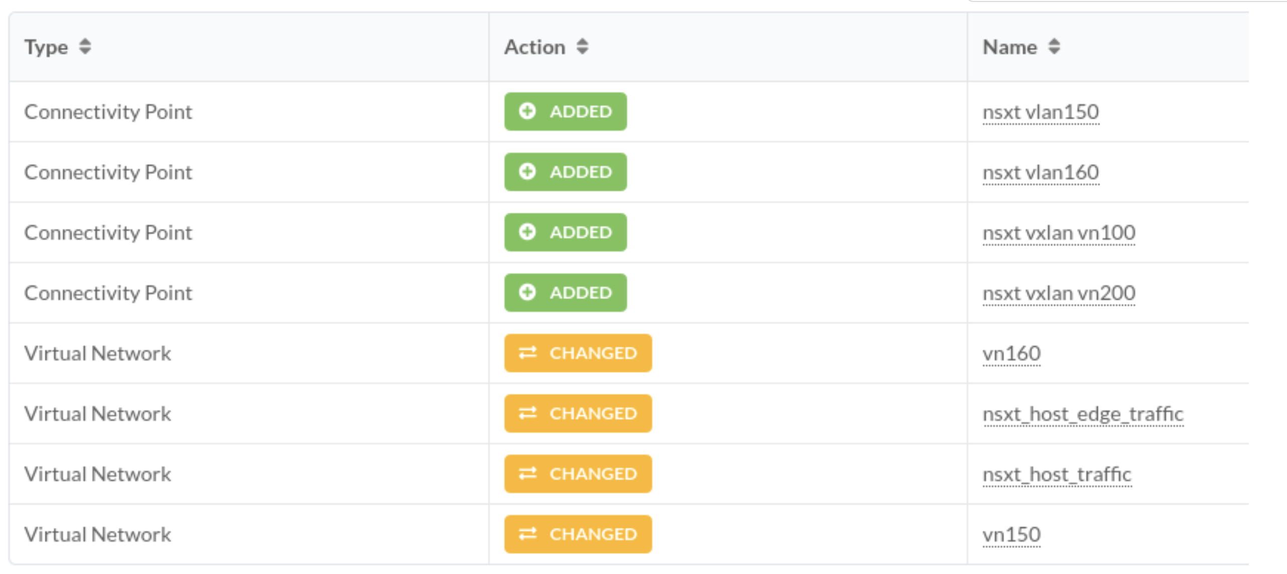
- From the Apstra GUI, setup the Routing Zone and the respective VNs on
which BGP session will be established towards ToR leaf devices as below:
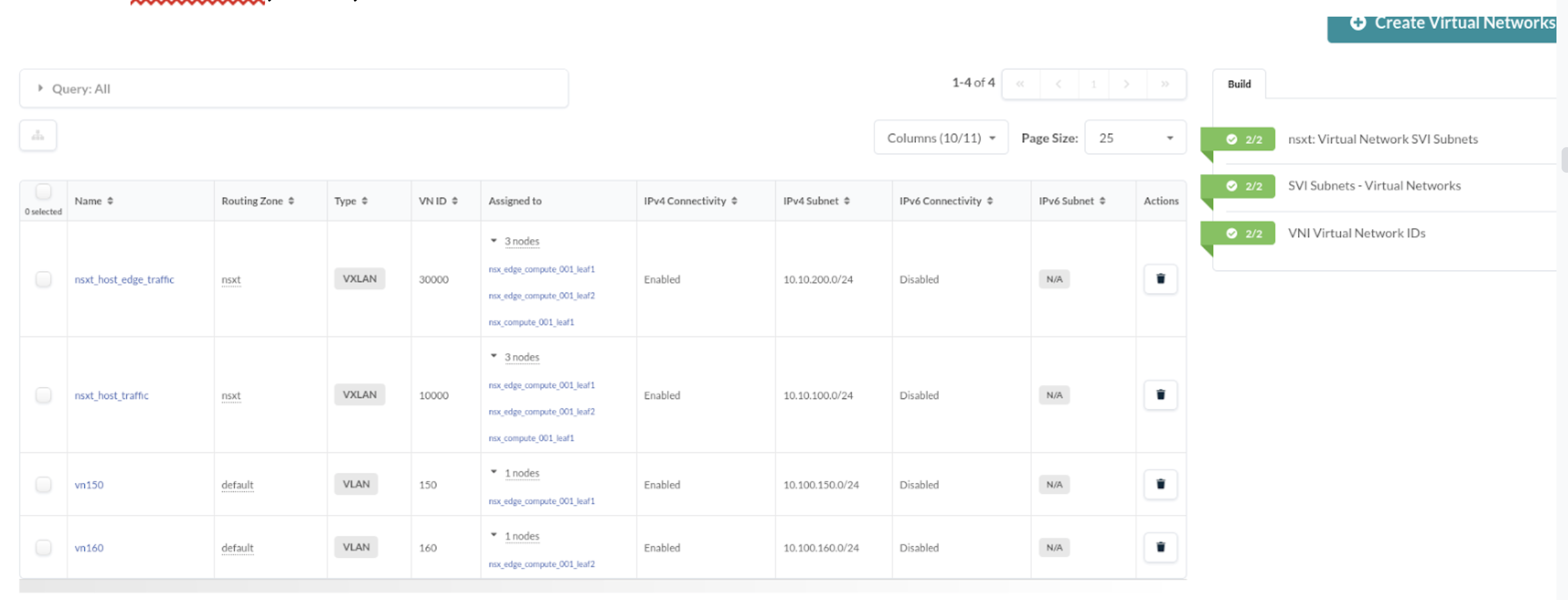
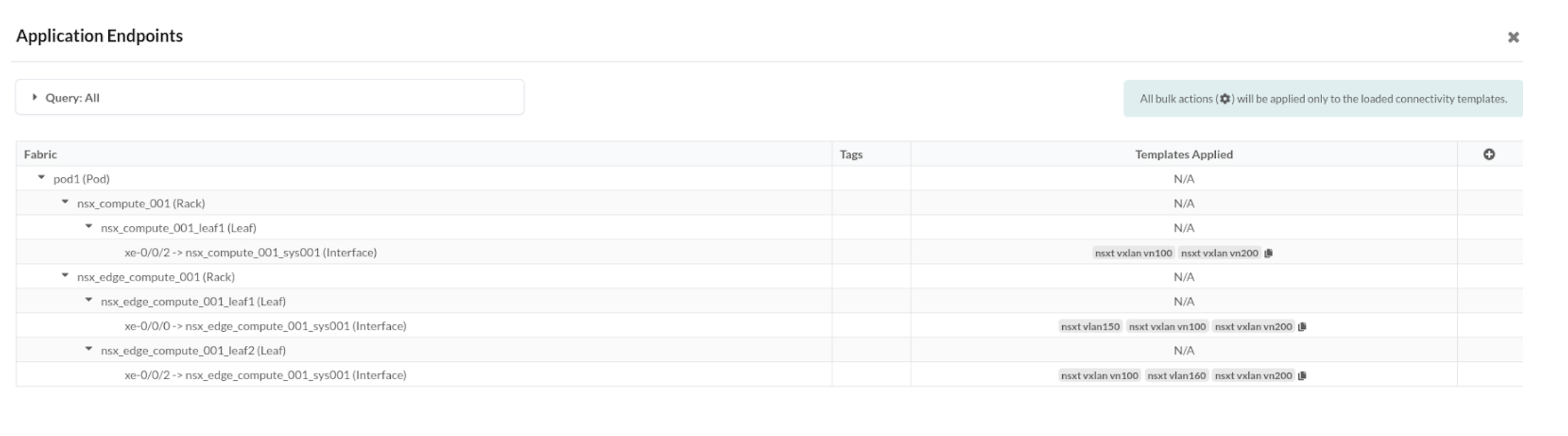
- Create connectivity template under Staged option for the VNs created before and
assign the respective interfaces towards NSX-T Edge VM.
Set Up Default Static Route towards NSX-T Edge
Static default could be required in NSX-T edge setup to provide Internet connectivity. It can be taken care of by adding a default route(0/0) with the next hop pointing towards uplink ToR leaf using a connectivity template.
In the connectivity templates, assign the correct uplink:
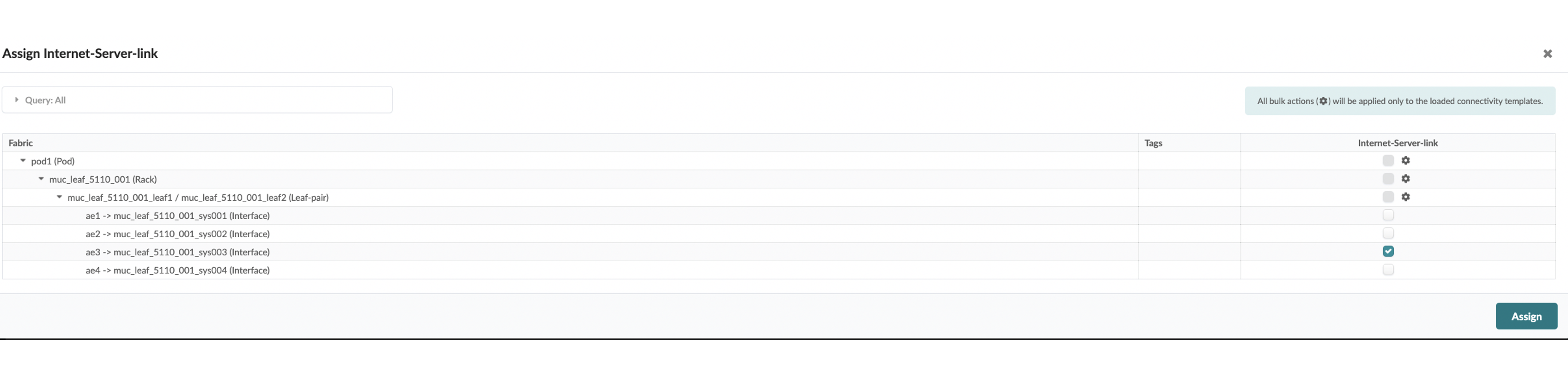
Navigate to Staged > Connectivity Templates > Add Template >
Primitives > Custom Static Route to inject default route:
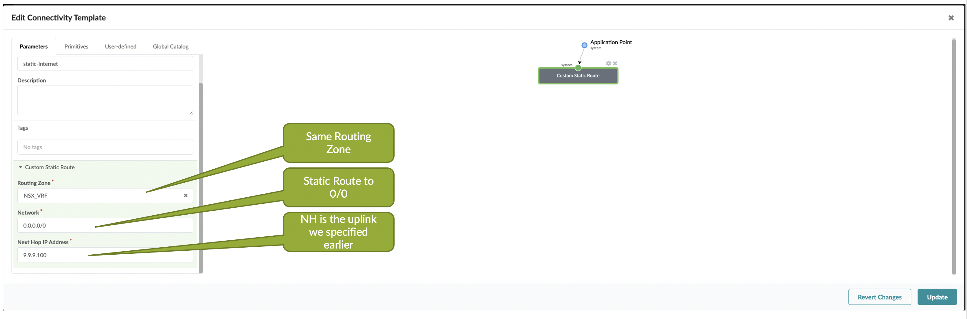
Set Up BGP IPv6 towards NSX-T Edge
We can enable IPv6-based BGP neighborship between T0 Gateway and ToR leaf using connectivity templates.
See "Set up NSX-T VRF Lite" section for details on creating uplink VLAN interfaces on T0 Gateway. This VLAN should be IPv6-enabled.
Create a connectivity template for each of the VXLAN VN and enable BGP towards IPv6
neighbor on NSX-T Edge as below:
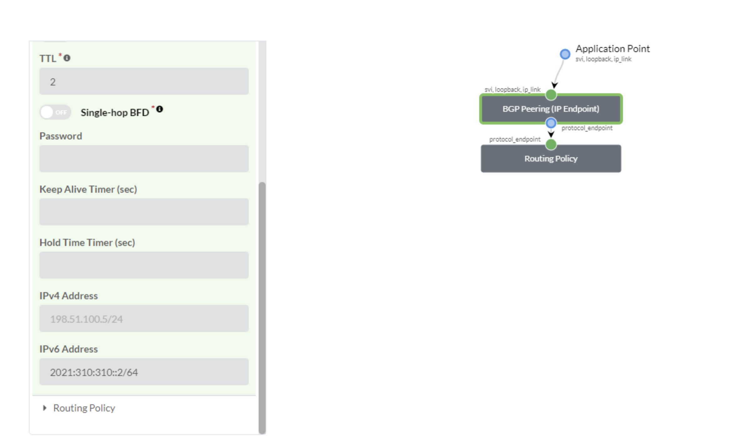
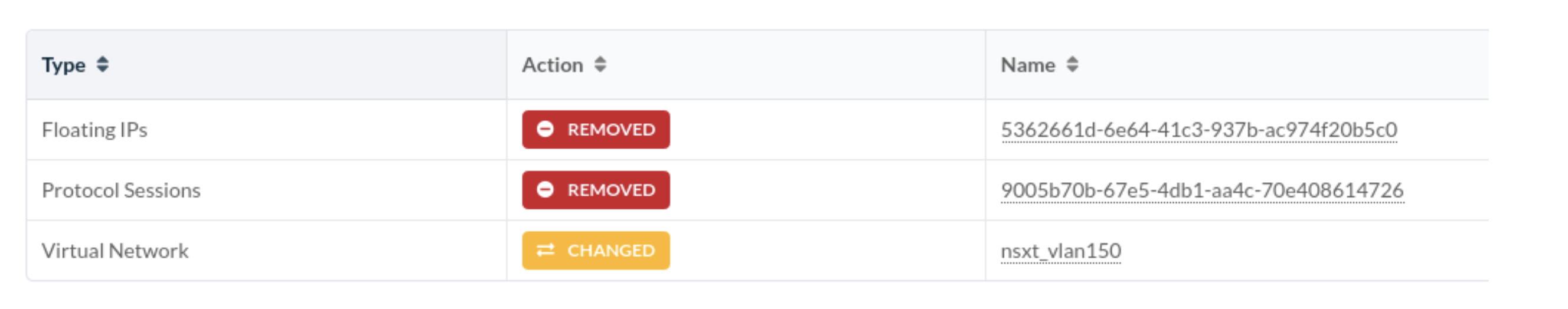
Un-assign BGP on VXLAN VN towards NSX-T Edge
Let's say BGP neighborship from Tier-0 Gateway in NSX-T needs to be torn down towards
ToR Leaf. In this case we need to unassign the interfaces in the Virtual
Network based Connectivity Template used for BGP peering so that it is in
the Ready state, and then delete the connectivity template: