Extend Virtual Networks to Apstra
SUMMARY Starting in CN2 Release 23.1 or later, you can extend virtual networks from your Kubernetes cluster to the datacenter fabric managed by Apstra.
Overview
Data centers typically have a mix of containerized workloads (SR-IOV pods, non-SR-IOV pods) and BMS. SR-IOV servers are being used extensively in data centers as these servers enable efficient I/O virtualization. When you create workloads on SR-IOV servers and attach virtual functions to the pods, the workloads use the fabric underlay directly. However, you might have a scenario where there is a need for communication between SRIOV pods, non-SRIOV pods, and BMS.
The different types of workloads are as follows:
-
SR-IOV pods: SR-IOV pods use the IP fabric underlay directly for communication. The SR-IOV technology enables the physical NIC to be split into several virtual functions. The pods attach to the virtual functions of the SR-IOV enabled NICs. SR-IOV-enabled NICs on servers are used to deliver efficient I/O virtualization. These virtual NICs or virtual functions can transmit and receive packets directly from the fabric to which the CN2 data network is attached.
-
Non-SR-IOV pods: Non-SR-IOV pods use the vRouter overlays for communication with other non-SR-IOV pods.
-
BMS: BMS are physical nodes and are not part of the CN2 cluster. BMS use the fabric underlay for communication with pods. On the BMS, you can run applications directly on the native OS or run applications on containers.
Juniper Apstra is used to provision the fabric to provide the required underlay connectivity for the different workloads. Apstra is Juniper’s intent-based networking software that automates and validates the design, deployment, and operation of data center networks. CN2 integrates with the Apstra software to provision the fabric underlay. For more information about Apstra, see the Juniper Apstra User Guide.
We refer to primary nodes in our documentation. Kubernetes refers to master nodes. References in this guide to primary nodes correlate with master nodes in Kubernetes terminology.
Example: CN2 Kubernetes Deployment with SR-IOV Pods
Figure 1 shows an example of a CN2 Kubernetes deployment. This deployment uses Apstra to provision the IP fabric underlay for the SR-IOV pods. Table 1 describes the different components.

| Component | Description |
|---|---|
| SR-IOV worker nodes | The SR-IOV worker nodes connect to the leaf devices in the IP
fabric. These nodes, which are part of the CN2 cluster, have
SRIOV-enabled NICs which can be split into virtual functions.
When you create a pod on an SR-IOV worker node, the pod's interface can be attached to a virtual function on the SR-IOV-enabled NIC. The SRIOV-enabled NICs are in turn connected to the leaf devices in the IP fabric. |
| CN2 Apstra plug-in | The CN2 Apstra plug-in extends the virtual network to the IP fabric. This plug-in listens for CN2 Kubernetes events such as creating a NAD, attaching pods to the virtual network, and creating a Virtual Network Router (VNR). The plug-in then configures the IP fabric for the underlay through Apstra. |
| Apstra | Apstra provisions the IP fabric to provide the required underlay connectivity for SR-IOV pods. Apstra also provides topology information regarding which leaf port is connected to which worker node. The CN2 Apstra plug-in uses this information to configure virtual network membership. The plug-in configures virtual-network membership on relevant fabric ports based on the worker node in which the SR-IOV pod is spawned. |
Prerequisites
To use this feature, you must install the following:
-
Juniper Apstra version 4.1.2 or higher
-
A CN2 cluster with the following items installed:
-
SR-IOV worker nodes that have SR-IOV-enabled NICs
-
Non-SR-IOV worker nodes
-
-
The following plug-ins:
-
Multus Plug-In
-
SR-IOV Network Device Plug-In
-
CN2 IPAM Plug-In
-
-
Licenses on the switches you are using in your topology
Juniper QFX switches require software licenses for advanced features. To ensure your that your IP fabric has the required licenses, see the Juniper Networks Licensing Guide.
Note:Make sure that you onboard the fabric to your Apstra blueprint as described in Step 4 in the Installation Workflow.
Considerations
Read through this list of considerations before you begin the installation:
-
This feature assumes:
-
CN2 single-cluster deployments
-
Basic approaches for Intra-VN and Inter-VN communication between SR-IOV pods, non-SR-IOV pods, and BMS. Other forms of routing, such as hub-and-spoke routing, are not supported.
-
A simple spine-leaf topology where the SR-IOV worker node is connected to only one leaf device. If an SR-IOV worker node is connected to multiple leaf ports, ensure that you configure all the leaf ports on all the leaf devices to which this SR-IOV worker node is connected.
-
-
Pods can be SR-IOV pods or non-SR-IOV pods. SR_IOV pods use the fabric underlay whereas Non-SR-IOV pods use the overlay though the vRouter.
-
BMS is not part of the CN2 cluster.
-
The entire BMS can be used exclusively for running applications directly on the host OS, where the IP is configured on the physical interface.
Or
BMS is running multiple VMs or containers, where the IP addresses are configured on the virtual interface.
-
In the Intra-VN approach, the same subnet is used by CN2 for allocating IPs to both SR-IOV and non-SRI-OV pods. From the same subnet, you must use the unallocated IPs for configuring IPs in the BMS.
-
When you create you a create BMS virtual network in Apstra, you must select all the leaf swtiches in that blueprint even if the BMS is connected to only one switch.
-
You cannot edit the fields in the virtual networks and NADs (such as vlanID and VNI) that were created in CN2. To change these fields, you must re-create the virtual networks and NADs.
-
Apstra accepts only VNIs greater or equal to 4096. Starting in CN2 release 23.1, on newer installations of CN2, we are allocating VNIs from 4096. Hence, this feature will not work on existing CN2 setups. If you have an existing CN2 setup upgraded from a previous release, you must run a script to release free VNIs whose value is less that 4096.
-
Ensure that the allocated vlanID does not conflict with those vlanID's allocated in Apstra. For example, you might want to use VLANs in the higher range (for example, 2000 and above) in CN2.
-
The IP addresses for the pods are automatically allocated by the CN2 IPAM plug-in.
-
In CN2, you must manually configure the routes on the pods for Inter-VN routing. For example: you can use the command
ip
                                    route add 10.30.30.0/8 via 10.20.20.1
to reach the10.30.30.0/8subnet. -
Overlapping IP addresses and bonded interfaces (link from the SR-IOV-enabled NICs to the leaf switches) are not in use.
-
Only IPv4 addressing is supported for this feature.
Installation Workflow
Follow the steps in this procedure to install and to configure the CN2 Apstra plug-in and its prerequisites:
-
Install the Apstra Software.
Install and configure Apstra version 4.1.2 or higher. See the Juniper Apstra Installation and Upgrade Guide.
If you have an existing data center network, Apstra is already managing the fabric. Make sure that you assign the required resource pools such as ASNs and loopback IP addresses for the blueprint.
-
Install a CN2 Cluster.
Install and configure a CN2 cluster that contains Kubernetes worker nodes. See the Install sections in the CN2 Installation Guide for Upstream Kubernetes or CN2 Installation Guide for OpenShift Container Platforms for instructions.
-
Install the Plug-Ins.
-
Multus Plug-In:
This plug-in enables you to attach multiple network interfaces to pods. See the Multus CNI for Kubernetes or Multus CNI for OpenShift documentation for installation instructions.
-
SR-IOV Network Device Plug-In:
This plug-in discovers and advertises networking resources for SR-IOV virtual functions on a Kubernetes host. See the SR-IOV Network Device Plugin for Kubernetes or SR-IOV Network Device Plugin for OpenShift documentation for instructions.
-
CN2 Apstra Plug-In:
This plug-in is installed as part of the CN2 deployer. See Install and Configure the CN2 Apstra Plug-In to install the plug-in.
-
CN2 IPAM Plug-In:
This plug-in allocates IP addresses for the pods. You install this plug-in on the SR-IOV nodes. See Install the CN2 IPAM Plug-In to install the plug-in.
-
-
Onboard the IP Fabric in Apstra.
You onboard the fabric in Apstra from the Apstra Web GUI. For onboarding instructions, see the Juniper Apstra User Guide..
-
Make sure that you assign the required resource pools such as ASNs and loopback IP addresses to the blueprint.
-
Make sure that the hostnames of the generic systems (that is, servers) in your Apstra blueprint matches the hostnames of the corresponding CN2 nodes. You must also tag the SR-IOV link that connects the SRIOV-enabled NICs on the worker nodes to the fabric ports. You'll enter this same value in the
sriov_link_tagin the CN2 Apstra plug-in CRD when you install the plug-in. The following diagram shows an example of a topology in an Apstra blueprint where the hostnames of the generic system were edited to match the corresponding hostnames of the CN2 worker nodes. The diagram also shows the SRIOV tags that were configured for the aforementioned SR-IOV links.
-
-
Verify Your Installation.
See Verify Your Installation for instructions.
Install and Configure the CN2 Apstra Plug-In
This section describes how to install and configure the CN2 Apstra plug-in.
The CN2 Apstra plug-in is installed as part of the deployer. The CN2 Apstra plug-in extends the virtual network to the fabric, listens for CN2 Kubernetes events (such as NAD creation), and configures the fabric for the underlay through the Apstra SDK.
Depending on your installation, use the following files to install and configure the plug-in:
-
For Kubernetes, use the
single_cluster_deployer_example.yamlfile. -
For OpenShift, copy all the files in the
ocp/pluginsdirectory to one level up in the directory structure.
To install and configure the CN2 Apstra plug-in:
-
Uncomment the
apstra-plugin-secretandcontrail-apstra-pluginin yoursingle_cluster_deployer_example.yamlfile. -
Enter your Apstra credentials (username and password) in the
apstra-plugin-secretsection in the corresponding deployer file. Make sure that your credentials are base64 encoded.For example:
apiVersion: v1
data:
  password: YWRtaW4K
  username: YWRtaW4K
kind: Secret
metadata:
  name: apstra-plugin-secret
  namespace: contrail
type: Opaque
-
Enter the parameters for
blueprint name, server_ip, sriov_link
                                tag
in thecontrail-apstra-pluginas shown in the following example. Make sure that the parameter for thesriov_link tagis the same parameter that you specified in the Apstra.This example also shows the image URL from where it fetches the
contrail-apstra-pluginimage. You can edit the image URL, if needed. For example, you can change the value of therelease_numberin the image to23.1.apiVersion: plugins.juniper.net/v1alpha1 kind: ApstraPlugin metadata: name: contrail-apstra-plugin namespace: contrail spec: blueprint: "" common: containers: - image: enterprise-hub.juniper.net/contrail-container-prod/contrail-apstra-plugin:release_number name: contrail-apstra-plugin server_ip: "" sriov_link_tag: ""For help in understanding what each field means, run the
kubectl explain apstraplugin.speccommand.Note:The following example is only for informational purposes. You can run this command only after you deploy the CN2 Apstra plug-in.
kubectl explain apstraplugin.spec
KIND:     ApstraPlugin
VERSION:  plugins.juniper.net/v1alpha1

RESOURCE: spec <Object>

DESCRIPTION:
     ApstraPluginSpec defines the desired state of ApstraPlugin

FIELDS:
   blueprint	<string>
     The BluePrint in Apstra managing the Fabric which acts as underlay for this
     CN2 instance

   common	<Object>
     Common configuration for k8s pods and containers

   log_level	<string>
     The log level of Apstra plugin


   server_ip	<string>
     The Apstra server IP address

   sriov_link_tag	<string>
     Contains the tag value(eg: SRIOV) for the SRIOV links in Apstra BluePrint
With the above steps, you have made the required changes in the deployer to install the CN2 Apstra plug-in. You can now proceed with the CN2 installation by following the instructions in the CN2 Installation Guide for Upstream Kubernetes or the CN2 Installation Guide for OpenShift Container Platforms.
Even after you have completed the CN2 installation, you can still edit the CN2 Apstra plug-in parameters in the deployer YAML(s) as mentioned in the above steps and then reinstall CN2.
Verify Your Installation
Run the following kubectl commands to verify that your
installation is up and running. For example:
Check for the multus plug-in.
kubectl get pods -A | grep multus
kube-system       kube-multus-ds-dn5j8                                    1/1     Running   1              26d
kube-system       kube-multus-ds-mnd4j                                    1/1     Running   1              26d
kube-system       kube-multus-ds-xvt5v                                    1/1     Running   2              26d-
-----------------------------------------------------------------------------------------------------------------
Check for the sriov-device-plugin.
kubectl get pods -A | grep sriov-device-plugin
kube-system       kube-sriov-device-plugin-amd64-2l792                    1/1     Running   0              6d8h
kube-system       kube-sriov-device-plugin-amd64-n2lxv                    1/1     Running   1              6d8h
kube-system       kube-sriov-device-plugin-amd64-v8tqx                    1/1     Running   1              26d
------------------------------------------------------------------------------------------------------------------
Check if the virtual functions were discovered.
kubectl describe node jfm-qnc-05.lab.juniper.net | grep -A8 Allocatable
Allocatable:
  cpu:                              64
  ephemeral-storage:                189217404206
  hugepages-1Gi:                    0
  hugepages-2Mi:                    0
  intel.com/intel_sriov_netdevice:  7
  memory:                           263710404Ki
  pods:                             110
System Info:
----------------------------------------------------------------------------------------------------------
Check for the Apstra plug-in CRDs.
kubectl api-resources | grep apstra
apstraplugins                   plugins.juniper.net/v1alpha1                true         ApstraPlugin

-----------------------------------------------------------------------------------------------------------
Check for the Apstra secret.
kubectl get secrets -A | grep apstra
contrail          apstra-plugin-secret        Opaque              2      20d

-----------------------------------------------------------------------------------------------------------
Check for the contrail-apstra-plugin pod.
kubectl get pods -A | grep apstra
contrail          contrail-apstra-plugin-fd86dd969-5s94s                  1/1     Running   8 (6d7h ago)   12d
Install the CN2 IPAM Plug-In
Follow this procedure to install the CN2 IPAM plug-in for both Kubernetes and OpenShift deployments. This procedure assumes that CN2 is already installed on a Kubernetes cluster. In this procedure, we show a single-cluster deployment.
To install and configure the CN2 IPAM plug-in:
Intra-VN and Inter-VN Approaches
This section shows the two approaches to configuring communication between SR-IOV pods, non-SR-IOV pods, and BMS: Intra-VN and Inter-VN.
You can use the Intra-VN approach or the Inter-VN approach depending on your requirement. If you want to see a summary of the configuration workflow for each approach, see Table 2 or Table 3.
Intra-VN Approach
In the Intra-VN approach, pods are attached to the same virtual network. By default, pods on the same virtual network can communicate with one another, regardless of whether:
The pods are spawned on the same worker nodes or on different worker nodes.
Or
The worker nodes are connected to the same leaf device or to a different leaf.
- Intra-VN Approach: Communication Between SR-IOV Pods
- Intra-VN Approach: Communication Between SR-IOV Pods, Non-SR-IOV Pods, and BMS
Intra-VN Approach: Communication Between SR-IOV Pods
Figure 2 shows an example of an Intra-VN topology where SR-IOV pods are attached to the same virtual network. This spine-and-leaf topology shows two SR-IOV worker nodes. Each node has a physical NIC with SR-IOV enabled. These physical NICs (ens801f2 and ens801f3) can be split into virtual functions and attached to the pods for direct I/O. When packets travel these virtual functions, the packets are tagged with the appropriate VLAN. In this approach, the packets do not pass through the vRouter but go directly to the IP fabric underlay provisioned by Apstra.

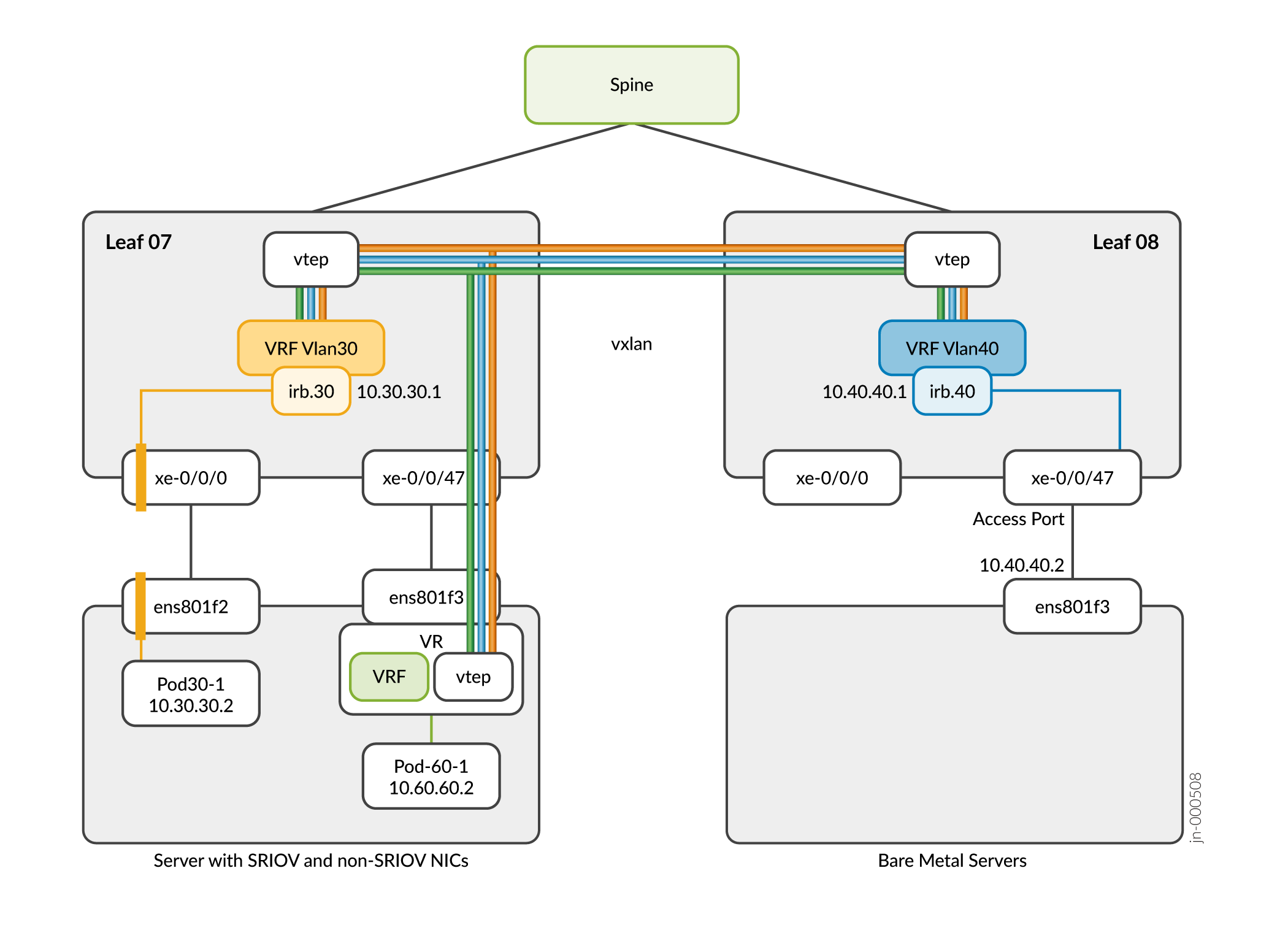
Intra-VN Approach: Communication Between SR-IOV Pods, Non-SR-IOV Pods, and BMS
Figure 3 shows an example of SR-IOV pods, non-SR-IOV pods, and BMS attached to the same virtual network. The pods and BMS in this example use the same VNI and subnet.
In this approach, an EVPN session is set up between the CN2 control node and the IP fabric to mutually exchange EVPN Type-2 routes used by the VXLAN protocol. The VTEP interface for the SR-IOV pods and BMS is on the fabric. The VTEP interface for the non-SR-IOV pods resides on the vRouter.
In the following figure, BMS is attached to the same virtual network as the SR-IOV and non-SR-IOV pods, but is not part of the CN2 cluster.

For information on configuring Intra-VN communication, see Introduction to Configuring Intra-VN Communication.
Inter-VN Approach
In the Inter-VN approach, CN2 pods and BMS workloads are attached to different virtual networks. The following sections shows the configuration required for configuring communication between pods and BMS.-
- Inter-VN Approach: Communication Between SR-IOV Pods
- Inter-VN Approach: Communication Between SR-IOV Pods, Non-SR-IOV Pods, and BMS
Inter-VN Approach: Communication Between SR-IOV Pods
The following figure shows an example of an Inter-VN topology between SR-IOV pods.

Inter-VN Approach: Communication Between SR-IOV Pods, Non-SR-IOV Pods, and BMS
In the Inter-VN approach, the pods and BMS belong to different virtual networks. To enable this communication, we are using EVPN Type-5 route exchanges between the CN2 control node and the fabric. For example:
For information on configuring Inter-VN communication, see Introduction to Configuring Inter-VN Communication.
Introduction to Configuring Intra-VN Communication
Table 2 summarizes the procedures required to configure Intra-VN communication between:
-
SR-IOV pods and other SR-IOV pods
-
SR-IOV pods and non-SR-IOV pods
-
SR-IOV pods, non-SR-IOV pods and BMS
Review Prerequisites and Intra-VN Approach before proceeding to the table.
| SR-IOV Pods | Non-SR-IOV Pods | Non-SR-IOV Pods and BMS | |
|---|---|---|---|
| SR-IOV Pods |
For detailed information for each step, see Configure Intra-VN Communication Between SR-IOV Pods. |
Pre-configuration setup (perform only once)
Configuration steps
For detailed information for each step, see Configure Intra-VN Communication Between SR-IOV Pods and Non-SR-IOV Pods. |
For detailed information for each step, see Configure Intra-VN Communication Between SR-IOV Pods, Non-SR-IOV Pods, and BMS. |
Configure Intra-VN Communication
Follow the procedures in this section to configure Intra-VN communication between SR-IOV pods, non-SR-IOV pods, and BMS.
- Before You Begin
- Configure Intra-VN Communication Between SR-IOV Pods
- Configure Intra-VN Communication Between SR-IOV Pods and Non-SR-IOV Pods
- Configure Intra-VN Communication Between SR-IOV Pods, Non-SR-IOV Pods, and BMS
Before You Begin
Read through this list of considerations before you begin your configuration:
-
In the Intra-VN approach, you use the same subnet across the pods and BMS. When configuring IP addresses in BMS, it is important to use the unallocated IP addresses to avoid collision with the IPs allocated by CN2.
For example: If the subnet is 10.20.20.0/24, CN2 allocates IP addresses to the pod from the lower end, like 10.20.20.2, 10.20.20.3, and so on. For BMS, we suggest that you use IP addresses in the higher end, like 10.20.20.200, 10.20.20.201, 10.20.20.202 to avoid a collision.
Depending on whether you configure the IP on the physical interface or on the virtual interface, you must use use the appropriate connectivity template (untagged or tagged, respectively) in Apstra. The template is used to configure the ports that connect the BMS to the fabric. See the Juniper Apstra User Guide for more information.
-
To configure communication between SR-IOV pods and BMS or communication between non-SR-IOV pods and BMS, see Configure Intra-VN Communication Between SR-IOV Pods, Non-SR-IOV Pods, and BMS.
Configure Intra-VN Communication Between SR-IOV Pods
To configure Intra-VN communication between SR-IOV pods:
Configure Intra-VN Communication Between SR-IOV Pods and Non-SR-IOV Pods
-
Change the encapsulation priority to
vxlanin CN2 using thekubectl edit GlobalVrouterConfig default-global-vrouter-configcommand. -
Create a remote EVPN gateway in Apstra. See the "Remote EVPN Gateways (virtual)" chapter in the Juniper Apstra User Guide for instructions.
-
In CN2, configure a
BGPRouter.In the following example, we are referencing the fabric's loopback IP address: (
10.1.1.3), ASN number (65003), and family (- e-vpn) used to exchange EVPN Type-2 routes.apiVersion: core.contrail.juniper.net/v3 kind: BGPRouter metadata: namespace: contrail name: bgprouter-qfx annotations: core.juniper.net/display-name: Sample BGP Router core.juniper.net/description: Represents configuration of BGP peers. All the BGP peers involved in Contrail system are under default Routing Instance of the default Virtual Network. spec: parent: apiVersion: core.contrail.juniper.net/v3 kind: RoutingInstance namespace: contrail name: default bgpRouterParameters: vendor: Juniper routerType: router address: 10.1.1.3 identifier: 10.1.1.3 autonomousSystem: 65003 addressFamilies: family: - e-vpn bgpRouterReferences: - apiVersion: core.contrail.juniper.net/v3 kind: BGPRouter namespace: contrail name: jfm-qnc-06.englab.juniper.net
To configure Intra-VN communication between SR-IOV pods and non-SR-IOV pods:
Configure Intra-VN Communication Between SR-IOV Pods, Non-SR-IOV Pods, and BMS
This procedure describes how to configure Intra-VN communication between SR-IOV pods, non-SR-IOV pods, and BMS.
-
For communication between SR-IOV pods and BMS, follow these steps but do not create a non-SR-IOV NAD and non-SR-IOV pod.
-
For communication between non-SR-IOV pods and BMS, follow these steps but do not create an SR-IOV NAD and SR-IOV pod.
To configure Intra-VN communication between SR-IOV pods, non-SR-IOV pods, and BMS:
Introduction to Configuring Inter-VN Communication
Table 3 summarizes the procedures required to configure Inter-VN communication between:
-
SR-IOV pods and other SR-IOV pods
-
SR-IOV pods and non-SR-IOV pods
-
SR-IOV pods, non-SR-IOV pods, and BMS
Review the Prerequisites and Inter-VN Approach before proceeding to the table.
| SR-IOV Pods | Non-SR-IOV Pods | Non-SR-IOV Pods and BMS | |
|---|---|---|---|
| SR-IOV Pods |
For detailed information for each step, see Configure Inter-VN Communication Between SR-IOV Pods. |
Pre-configuration setup (perform only once)
Configuration steps
For detailed information for each step, see Configure Inter-VN Communication Between SR-IOV Pods and Non-SR-IOV Pods. |
For detailed information for each step, see Configure Inter-VN Communication Between SR-IOV Pods, Non-SRIOV Pods and BMS. |
Configure Inter-VN Communication
Follow the procedures in this section to configure Inter-VN communication between SR-IOV pods, non-SR-IOV pods, and BMS.
Before You Begin
Read through the this list of considerations before you begin your configuration:
-
For Inter-VN routing, you must create a
VirtualNetworkRouterin CN2. -
In the Inter-VN approach, you must manually configure the routes on the pods. For example: you can use the command
ip route add
                                10.30.30.0/8 via 10.20.20.1
to reach the10.30.30.0/8subnet. -
The QFX5200 switch does not support EVPN Type-5 routing and edge-routing bridging (ERB). See Edge-Routing Bridging for QFX Series Switches for more information.
For a list of supported Juniper devices for use in an Inter-VN topology, see Layer 3 connectivity in an EVPN-VXLAN topology. Also, make sure that the QFX devices are running Junos OS version 20.2R2.11 or above.
Configure Inter-VN Communication Between SR-IOV Pods
To configure Inter-VN communication between SR-IOV pods:
Configure Inter-VN Communication Between SR-IOV Pods and Non-SR-IOV Pods
-
Change the encapsulation priority to
vxlanin CN2 using thekubectl edit GlobalVrouterConfig default-global-vrouter-configcommand. -
Create a remote EVPN gateway in Apstra. See the "Remote EVPN Gateways (virtual)" chapter in the Juniper Apstra User Guide for instructions.
-
In CN2, configure a
BGPRouter.In the following example, we are referencing the fabric's loopback IP address: (
10.1.1.3), ASN number (65003), and family (- e-vpn) used to exchange EVPN Type-2 routes.apiVersion: core.contrail.juniper.net/v3 kind: BGPRouter metadata: namespace: contrail name: bgprouter-qfx annotations: core.juniper.net/display-name: Sample BGP Router core.juniper.net/description: Represents configuration of BGP peers. All the BGP peers involved in Contrail system are under default Routing Instance of the default Virtual Network. spec: parent: apiVersion: core.contrail.juniper.net/v3 kind: RoutingInstance namespace: contrail name: default bgpRouterParameters: vendor: Juniper routerType: router address: 10.1.1.3 identifier: 10.1.1.3 autonomousSystem: 65003 addressFamilies: family: - e-vpn bgpRouterReferences: - apiVersion: core.contrail.juniper.net/v3 kind: BGPRouter namespace: contrail name: jfm-qnc-06.englab.juniper.net
To configure Inter-VN communication between SR-IOV pods and non-SR-IOV pods:
Configure Inter-VN Communication Between SR-IOV Pods, Non-SRIOV Pods and BMS
To configure Inter-VN communication between SR-IOV pods, non-SR-IOV pods, and BMS: