Onboard the Fabric
SUMMARY In this section, you are using Contrail Command to configure your zeroized fabric devices to be part of a single physical underlay network.
Explanation of Procedure
The recommended first step to onboarding a fabric is to tell Contrail Networking about the devices in the fabric. You do this by creating a YAML file containing the list of serial numbers of all devices in the fabric. For convenience, Contrail Command provides you with a template that you can use.
You then upload this file to Contrail Networking when you run the Create Fabric wizard, which guides you through fabric creation, including performing zero-touch-provisioning (ztp) of the devices in the list.
In a regular network, you typically onboard the fabric once at the beginning and whenever you add or remove devices from the fabric. In this latter case, you would be onboarding specific devices onto the fabric rather than creating a fabric from scratch.
All devices should be in zeroized state (request system zeroize from the CLI) before you perform the initial onboarding.
Configure the Device YAML File
The device YAML file is the file that contains the list of serial numbers of all fabric devices. The device YAML file also contains configuration that you want Contrail Networking to apply as part of onboarding the fabric. You create the device YAML file on the computer that you use to connect to Contrail Command. This can be your local computer as long as it has access to the management network where the Contrail Networking installation resides.
The YAML file must comply with the syntax specified in //yaml.org including spacing and indentations, which act as delimiters. By convention, a YAML file has a .yaml or .yml file extension.
For convenience, you can download a YAML file template from Contrail Command when you use the Create Fabric wizard (see step 4 in Configure the Device YAML File).
A very basic device YAML file just contains the chassis serial numbers of the devices and looks like this:
To get the chassis serial number from your device, issue the show chassis hardware command from the Junos CLI on the device. Alternatively, you can get the chassis serial number from the label affixed to your device. See Locating the Chassis Serial Number ID Label on a QFX10008 or QFX10016 and Locating the Serial Number on a QFX5100 Device or Component.
device_to_ztp:
  - serial_number: '111111111111'
  - serial_number: ’222222222222’
  - serial_number: '333333333333’
  - serial_number: '444444444444'
  - serial_number: '555555555555'
It’s a good idea, however, to include the hostnames of the devices. Otherwise, Contrail Command displays and refers to the devices by their serial numbers. The example below adds meaningful hostnames to identify the spine and leaf switches.
device_to_ztp:
  - serial_number: '111111111111'
    hostname: 'DC1-Access-Leaf-1'
  - serial_number: ’222222222222’
    hostname: 'DC1-Access-Leaf-2'
  - serial_number: '333333333333’
    hostname: 'DC1-Access-Leaf-3'
  - serial_number: '444444444444'
    hostname: 'DC1-Border-Spine-1'
  - serial_number: '555555555555'
    hostname: 'DC1-Border-Spine-2'
That’s all you really need for the device YAML file. However, the YAML file in this use case contains a few more constructs to demonstrate its flexibility and power and to save you some additional configuration later on.
The YAML file used in this example is shown below:
supplemental_day_0_cfg:
  - name: '10k-spine-cfg'
    cfg: |
      set system location rack 10
  - name: '5kleaf-cfg'
    cfg: |
      set system location rack 5
device_to_ztp:
  - serial_number: '111111111111'
    supplemental_day_0_cfg: '5kleaf-cfg'
    hostname: 'DC1-Access-Leaf-1'
    device_functional_group: 'L2-Server-Leaf'
  - serial_number: ’222222222222’
    supplemental_day_0_cfg: '5kleaf-cfg'
    hostname: 'DC1-Access-Leaf-2'
    device_functional_group: 'L2-Server-Leaf'
  - serial_number: '333333333333’
    supplemental_day_0_cfg: '5kleaf-cfg'
    hostname: 'DC1-Access-Leaf-3'
    device_functional_group: 'L2-Server-Leaf'
  - serial_number: '444444444444'
    supplemental_day_0_cfg: '10k-spine-cfg'
    hostname: 'DC1-Border-Spine-1'
    device_functional_group: 'Centrally-Routed-Border-Spine'
  - serial_number: '555555555555'
    supplemental_day_0_cfg: '10k-spine-cfg'
    hostname: 'DC1-Border-Spine-2'
    device_functional_group: 'Centrally-Routed-Border-Spine'
Table 1 contains the definitions of the constructs used in this YAML file and Table 2 shows the resulting actions on each fabric device when you later apply this YAML file to the fabric.
Fields |
Meaning |
|
|---|---|---|
device_to_ztp |
This mandatory section contains the fabric devices that you want to discover and configure. Each fabric device is organized in its own subsection. Each subsection is identified by the device’s serial number. |
|
serial_number |
This is the hardware serial number of the device. To see the serial number in Junos, issue the This field is mandatory. |
|
supplemental_day_0_cfg |
This field references the This field is optional. |
|
hostname |
This field sets the hostname on the device. This is equivalent to the Junos This field is optional but highly recommended. If you do not specify the hostname, Contrail Command displays the device using its serial number. |
|
device_functional_group |
This field applies the specified device functional group to the device. A device functional group is a user-defined node profile that automatically sets the roles for the device. This field is optional. If you do not specify a device functional group, you will need to specify the roles for the device explicitly when you create the fabric. To define the device functional groups used in this example, log in to Contrail Command and select INFRASTRUCTURE>Fabrics and then click on Device Functional Groups. Click Create to create the groups, as follows:
For more information on roles, see the Contrail Networking Fabric Lifecycle Management Guide. |
|
supplemental_day_0_cfg |
This optional section contains additional configuration that you can apply to the discovered devices. The additional configuration is organized into subsections identified by name. |
|
name |
This is the name of the additional configuration subsection. Devices in the |
|
cfg |
This contains the set of Junos CLI commands you want to execute on the device as part of device discovery. |
|
Device |
Actions |
|---|---|
111111111111 |
Sets the hostname to Sets the device functional group to
Issues the following CLI commands on the device: set system location rack 5 |
222222222222 |
Sets the hostname to Sets the device functional group to
Issues the following CLI commands on the device: set system location rack 5 |
333333333333 |
Sets the hostname to Sets the device functional group to
Issues the following CLI commands on the device: set system location rack 5 |
444444444444 |
Sets the hostname to Sets the device functional group to
Issues the following CLI commands on the device: set system location rack 10 |
555555555555 |
Sets the hostname to Sets the device functional group to
Issues the following CLI commands on the device: set system location rack 10 |
Once you have finished creating the YAML file and the device functional groups, you can proceed to the next step where you launch the Create Fabric wizard to start creating the fabric.
Create Fabric
This is the first stage of the Create Fabric wizard. You specify the basic underlay and overlay configuration parameters and you reference the device YAML file you created earlier.
Device Discovery
This is the second stage of the Create Fabric wizard. Contrail Networking begins the discovery process by responding to DHCP requests on the management subnet and then using NETCONF to configure the devices that match the serial numbers listed in the YAML file, including:
reading interface information, enabling LLDP, and bringing up interfaces
applying the standard juniper-qfx10k and juniper-qfx5k node profiles
assigning loopback IP addresses
running the supplementary commands from the YAML file
reading and storing inventory and other information from the devices
building the topology
At the completion of this stage, Contrail Networking has brought up all the fabric devices and has built the fabric topology.
Click Next to progress to role assignment.
Assign the Roles
This is the third stage of the Create Fabric wizard. At this point, Contrail Networking has discovered and performed initial configuration of the fabric devices and knows how they are connected together but does not yet know what roles the devices play in the fabric.
When you assign a role to a device, you are telling Contrail Networking what the device’s function is. A role is strictly a Contrail Networking construct and is an example of Contrail Networking’s intent-based provisioning. It is not a Junos parameter that you configure on a switch. Instead, you tell Contrail Networking what role you want a device to assume, and Contrail Networking then performs all the underlying configuration on the device to enact that role.
There are two types of roles that you assign to a device. The physical (underlay) role describes whether a device is a spine device or a leaf device. The routing (overlay) role describes the overlay routing functions that a device supports. While a device can only have one physical role, it is common and normal for a device to have multiple routing roles.
The Assign to devices window shows the list of discovered devices along with their assigned roles. In this use case, you assigned the roles using the device_functional_group parameter in the device YAML file so you don’t have to explicitly assign roles here.
Verify that the roles are as shown in Table 4 and Table 5. For more information on roles, see the Contrail Networking Fabric Lifecycle Management Guide.
Meaning |
Setting in this Example |
|
|---|---|---|
Role |
The physical or underlay role of the device. |
leaf |
Routing Roles |
The routing/bridging or overlay role of the device. |
CRB-Access |
AR-Client |
Meaning |
Setting in this Example |
|
|---|---|---|
Role |
The physical or underlay role of the device. |
spine |
Routing Roles |
The routing/bridging or overlay role of the device. |
CRB-Gateway |
DC-Gateway |
||
DCI-Gateway |
||
PNF-Servicechain |
||
Route-Reflector |
Click Autoconfigure to start the auto-configuration stage of the process.
Autoconfigure
This is the fourth stage of the Create Fabric wizard. Contrail Networking configures all the necessary parameters on the devices to support the roles they are given.
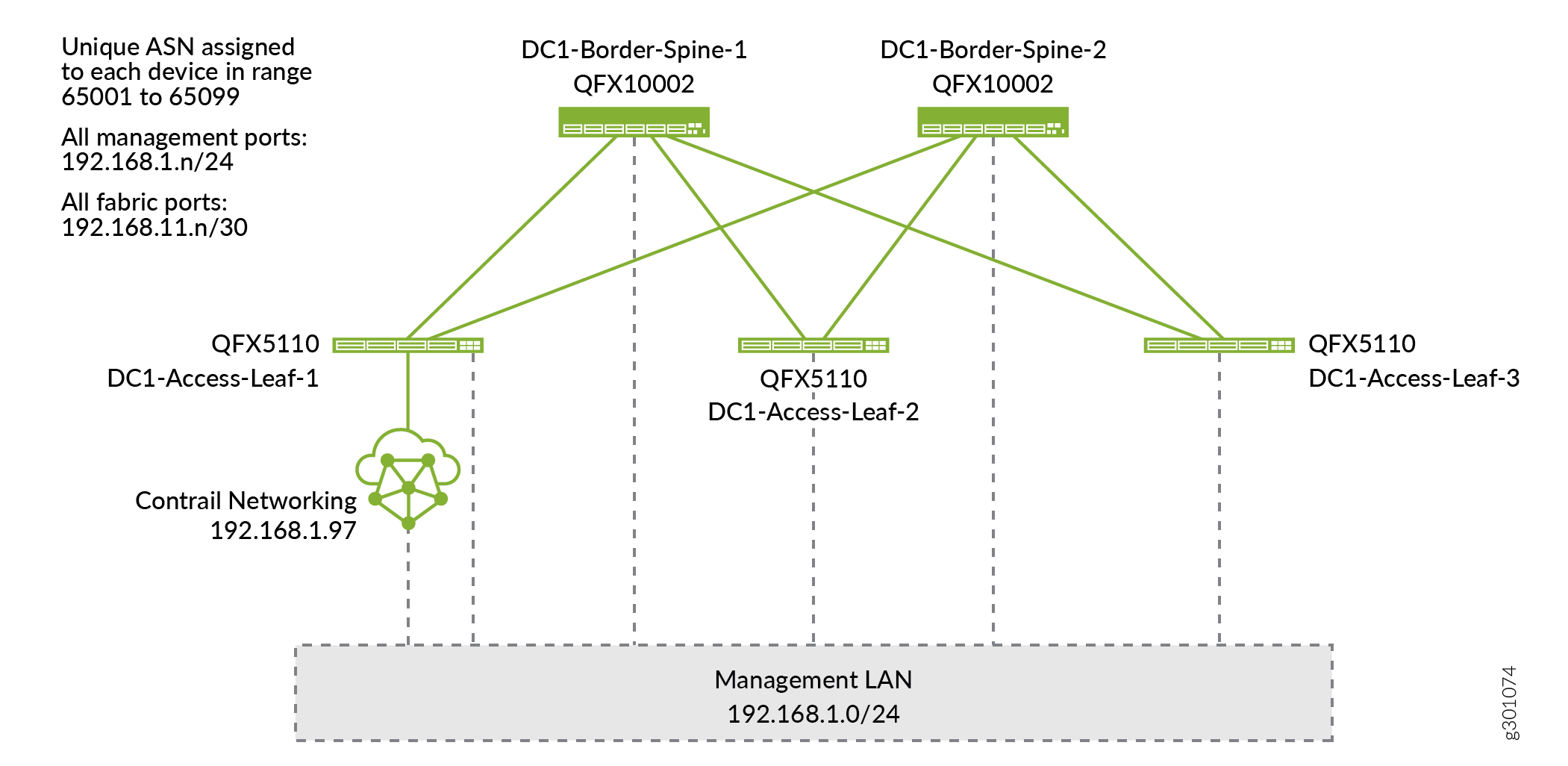
After auto-configuration is complete, the fabric is now up and running and ready for overlay configuration (Figure 1).
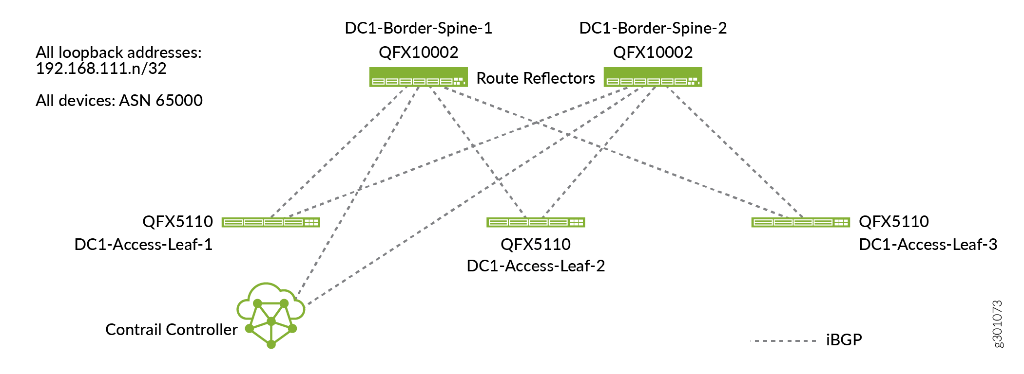
Additionally, the initial overlay BGP configuration is performed, identifying all overlay BGP speakers (including the Contrail Networking controller) and assigning the common overlay AS number (Figure 2).
Click Next to move to the next stage.
Assign Telemetry Profiles
This is the optional fifth and final stage of the Create Fabric wizard. You can assign telemetry profiles to any or all of the fabric devices in this stage. The Contrail Networking installation can include an sflow server for telemetry processing. When you assign a profile to a device, you are configuring the device to send telemetry data to this sflow server. For information on assigning telemetry profiles, see the Contrail Networking Fabric Lifecycle Management Guide.
This use case does not use telemetry profiles. Click Finish to exit the Create Fabric wizard.
Verify Underlay Configuration on the Device (Optional)
With just a few clicks, Contrail Networking has onboarded your fabric. If you want to see how Contrail Networking has configured your devices, you can log in to the individual devices to check.