Network Implementation Plan Overview
Paragon Automation uses a network implementation plan to commit configurations on the device during device onboarding, and update configurations after the device is onboarded. For example, if a plan has an RSVP LSP configured from a device to all the provider edge (PE) devices, an LSP is configured from the device to all the PE devices that are currently present in the network and also, to any PE device that might be added to the network after the device is onboarded.
Before you (a network planner) onboard a device, you must create a network implementation plan to define the device configurations to be committed, and health, connectivity, and compliance [with Center for Internet Security (CIS)] checks to be performed on the device.
Network implementation plans define which device profiles and interface profiles should be applied to a device or a group of devices during onboarding. The profiles define which interfaces to configure, with protocols to enable, with IP addresses to assign, and so on.
Paragon Automation maps the serial number of a device during onboarding with the serial number that is included in a particular network implementation plan and the corresponding device and interface profiles are then applied to the device.
A single network implementation plan can include one or more devices. If you want to onboard multiple devices, you can add all of them to a single implementation plan, and within the plan, reference a different device profile for each device or specify a default device profile that will be applied to all the devices.
Paragon Automation can manage up to 800 devices. You can onboard a maximum of three devices parallelly at a time.
Additionally, the implementation plan allows the user to provide any required information to build the configuration. For example, for a given interface, you can be referencing an interface profile that does not have automatic address assignment enabled. In the Network Implementation Plan, you will provide the IP address that you want to configure on that interface while creating the network implementation plan.
You create a plan by adding devices, assigning device and interface profiles to the devices, and defining links from the devices to neighboring devices. A device profile contains configurations associated with a device such as IP address, autonomous system (AS) the device is a part of, tunnels to be created on the device, and BGP groups. The interface profiles contain the protocol configuration (IS-IS, OSPF, BGP, and RSVP) for the interfaces. See Device and Interface Profiles Overview for more information.
Paragon Automation provides a wizard in the GUI that guides you to create the plan. To create a plan, navigate to Inventory > Device Onboarding > Network Implementation Plan.
In the plan, you:
-
Add one or more devices that you want to associate with the plan.
-
Assign one or more device profiles and interface profiles to the devices. You can also define default device or interface profiles that would be assigned to all the devices and their interfaces in the network implementation plan.
-
Enter instructions on the type of pluggables to insert and cables to use for connecting to the device ports.
A field technician can view these instructions on the field technician UI while installing the device. So, we recommend that you use terminologies with which a field technician is familiar. See Install and Onboard the Device (Day 0 Activities).
-
Add the number of hardware elements (pluggables, memory, PSU, and fans) in the device for collecting health data.
-
Configure links from the device to neighboring devices. You can configure links only between devices in the same network implementation plan.
You cannot onboard multiple devices in an Implementation plan at the same time.
Figure shows an example of a network implementation plan ISP1 created for onboarding an ACX7024 device with serial number 12345.
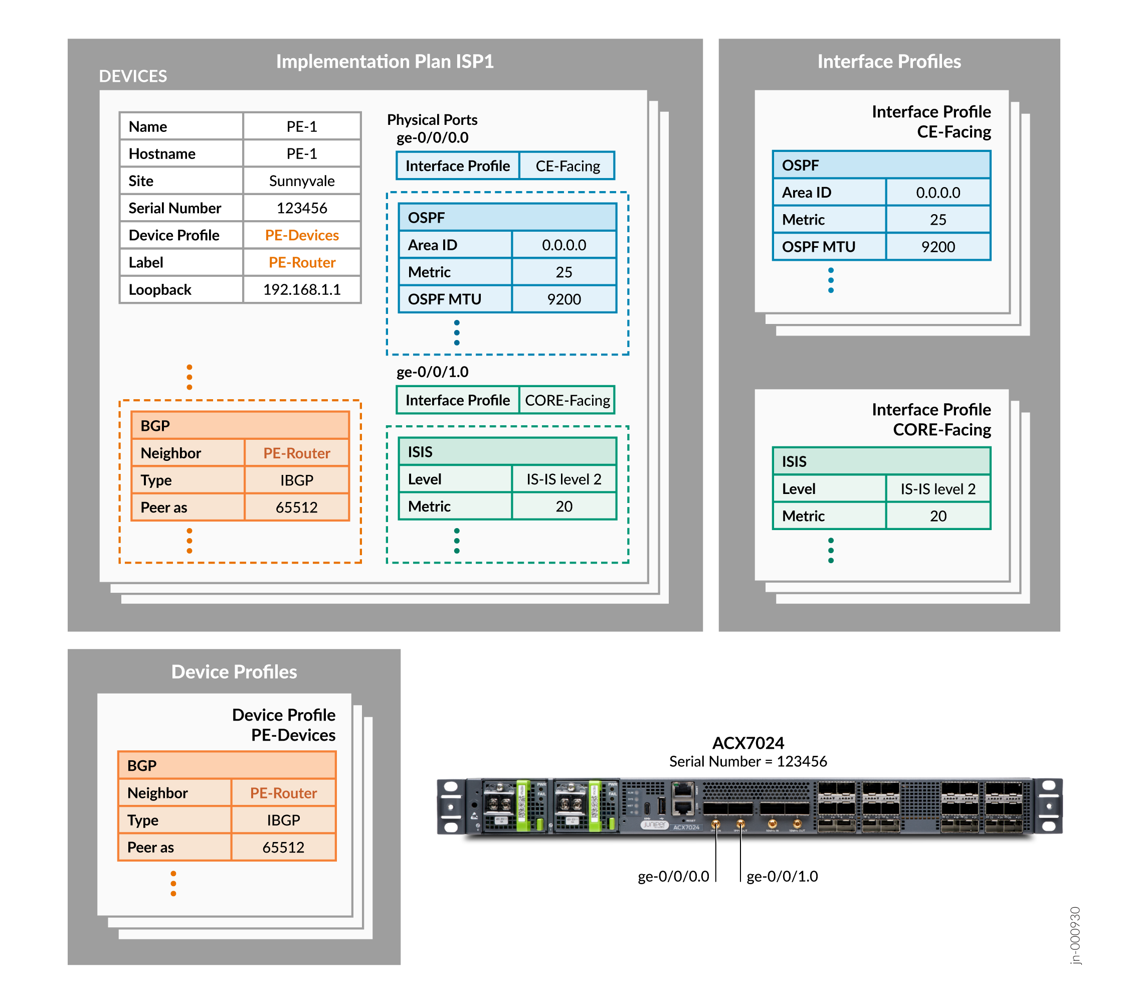
To onboard the ACX7024 device, Paragon Automation:
- Matches the serial number mentioned in the network implementation plan with the serial number of the ACX7024 device.
-
Tags the ACX 7024 device with the label PE-Router and configures:
-
PE-1 as the hostname
-
192.168.1.1 as the loopback interface IPv4 address
-
-
Configures iBGP on the ACX 7024 device based on the PE-Devices device profile and peers the device with other devices with the PE-Router label.
-
Configures Interface ge-0/0/0.0 to run OSPF with metric 25 and MTU 9200 based on the CE-FACING interface profile referenced for this interface.
-
Configures Interface ge-0/0/1.0 to run IS-IS level 2 with metric 20 and MTU 9200 based on the CORE-FACING interface profile referenced for this interface.
Benefits
-
A network architect can provide instructions on the type of pluggables and cables to be used for a port, to a field technician. This helps the field technician to install the correct pluggables and connect correct cables to ports.
-
By using a network implementation plan, you can define the configuration for multiple devices once and commit them when the devices are onboarded. To modify the committed configurations on the devices later, you can change the configuration in the plan and push the changes to the devices.
-
When you use a plan for onboarding a device, Paragon Automation executes the health and connectivity checks during device onboarding. The health and connectivity checks during onboarding help you to ensure that the device will function without issues after the device is onboarded and is ready for production soon after onboarding.
-
When you use a plan to onboard a device, based on the configurations in the plan, playbooks for collecting metrics are enabled automatically. You do not have to separately configure monitoring. For example, if you enable BGP, Paragon Automation collects metrics for BGP and displays the data on the Paragon Automation UI.
-
By defining the links between devices in the plan, the links are configured on the devices while the devices are onboarded, enabling quick deployment of your network.