ON THIS PAGE
Understand Chassis Alarms
This topic lists various chassis conditions that are configured to trigger alarms.
Chassis alarms are predefined alarms triggered by a physical condition on the device such as
a power supply failure or excessive component temperature. You can use the show chassis alarms command to display the chassis
alarm information for presently active alarms. Chassis alarms are preset. You cannot modify
them. You cannot clear the alarms for chassis components. Instead, you must remedy the cause
of the alarm.
Chassis Conditions That Trigger Alarms
Various conditions related to the chassis components trigger yellow and red alarms. You cannot configure these conditions.
- Backup Routing Engine Alarms
- Chassis Alarm Conditions for Guest Network Functions (GNFs)
- Chassis Alarm Conditions on MX Series 5G Universal Routing Platforms
- Chassis Alarm Conditions on SRX series devices
- Chassis Alarm Conditions for PTX Series Routers
- Chassis Alarm Conditions for ACX Series Routers
Backup Routing Engine Alarms
For routers with primary and backup Routing Engines, a primary Routing Engine can generate alarms for events that occur on a backup Routing Engine. Table 1 lists chassis alarms generated for a backup Routing Engine.
Because the failure occurs on the backup Routing Engine, alarm severity for some events (such as Ethernet interface failures) is yellow instead of red.
For information about configuring redundant Routing Engines, see the Junos OS High Availability Library for Routing Devices.
|
Chassis Component |
Alarm Condition |
Remedy |
Alarm Severity |
|---|---|---|---|
| Alternative media |
The backup Routing Engine boots from an alternate boot device, the hard disk. The CompactFlash card is typically the primary boot device. The Routing Engine boots from the hard disk when the primary boot device fails. |
Open a support case using the Case Manager link at https://www.juniper.net/support/ or call 1-888-314-JTAC (within the United States) or 1-408-745-9500 (from outside the United States). |
Yellow |
| Boot Device |
The boot device (CompactFlash or hard disk) is missing in boot list on the backup Routing Engine. |
Replace failed backup Routing Engine. |
Red |
| Ethernet |
The Ethernet management interface ( |
|
Yellow |
| FRU Offline |
The backup Routing Engine has stopped communicating with the master Routing Engine. |
Open a support case using the Case Manager link at https://www.juniper.net/support/ or call 1-888-314-JTAC (within the United States) or 1-408-745-9500 (from outside the United States). |
Yellow |
| Hard Disk |
Error in reading or writing hard disk on the backup Routing Engine. |
Reformat hard disk and install bootable image. If this fails, replace failed backup Routing Engine. |
Yellow |
| Multibit Memory ECC |
The backup Routing Engine reports a multibit ECC error. |
|
Yellow |
Chassis Alarm Conditions for Guest Network Functions (GNFs)
Table 2 lists the Chassis conditions that trigger alarms on guest network functions (GNFs).
Read more about GNFs in this Junos Node Slicing article.
|
Chassis Component |
Alarm Condition |
Remedy |
Alarm Severity |
|---|---|---|---|
| Routing Engine |
Mixed Master and Backup RE types This alarm is raised when the GNF primary Routing Engine and GNF Backup Routing Engine have been assigned either mismatching frequencies ( with difference above 100 MHz), mismatching numbers of cores, or DRAM. |
Correct the differences and then relaunch the corrected GNF Routing Engine. |
Yellow |
| Routing Engine |
System Incompatibility with BSYS The alarm is shown when any incompatibilities between BSYS and GNF software versions cause the GNF to go offline. |
Make the required changes to the BSYS or GNF software through upgrade. |
Red |
| Routing Engine |
Feature Incompatibility with BSYS Indicates a minor incompatibility between BSYS and GNF software versions. This could result in a:
|
Make the required changes to the BSYS or GNF software through upgrade. |
Yellow |
Chassis Alarm Conditions on MX Series 5G Universal Routing Platforms
Table 3 lists the alarms that the chassis components can generate on MX Series 5G Universal Routing Platforms. The messages that appear may vary depending on the platform and software release.
|
Chassis Component |
Alarm Condition |
Remedy |
Alarm Severity |
|---|---|---|---|
| Air filters |
Change air filter. |
Change air filter. |
Yellow |
| Alternative media |
The router boots from an alternate boot device, the hard disk. The CompactFlash card is typically the primary boot device. The Routing Engine boots from the hard disk when the primary boot device fails. |
Open a support case using the Case Manager link at https://www.juniper.net/support/ or call 1-888-314-JTAC (within the United States) or 1-408-745-9500 (from outside the United States). |
Yellow |
| Craft interface |
The craft interface has failed. |
Replace failed craft interface. |
Red |
| Dense Port Concentrators (DPC)s |
A DPC is offline. |
Check DPC. Remove and reinsert the DPC. If this fails, replace failed DPC. |
Yellow |
|
A DPC has failed. |
Replace failed DPC. |
Red |
|
|
A DPC has been removed. |
Insert DPC into empty slot. |
Red |
|
| Fan trays |
A fan tray has been removed from the chassis. |
Install missing fan tray. |
Red |
|
One fan in the chassis is not spinning or is spinning below required speed. |
Replace fan tray. |
Red |
|
|
A higher-cooling capacity fan tray is required when an MPC is installed on the chassis. |
Upgrade to a high-capacity fan tray. |
Yellow |
|
| Host subsystem |
A host subsystem has been removed. |
Insert host subsystem into empty slot. |
Yellow |
|
A host subsystem has failed. |
Replace failed host subsystem. |
Red |
|
| Hot swapping |
Too many hot-swap interrupts are occurring. This message generally indicates that a hardware component that plugs into the router’s backplane from the front (generally, an FPC) is broken. |
Replace failed component. |
Red |
| Power supplies |
A power supply has been removed from the chassis. |
Insert power supply into empty slot. |
Yellow |
|
A power supply has a high temperature. |
Replace failed power supply or power entry module. |
Red |
|
|
A power supply input has failed. |
Check power supply input connection. |
Red |
|
|
A power supply output has failed. |
Check power supply output connection. |
Red |
|
|
A power supply has failed. |
Replace failed power supply. |
Red |
|
|
Invalid AC power supply configuration. |
When two AC power supplies are installed, insert one power supply into an odd-numbered slot and the other power supply into an even-numbered slot. |
Red |
|
|
Invalid DC power supply configuration. |
When two DC power supplies are installed, insert one power supply into an odd-numbered slot and the other power supply into an even-numbered slot. |
Red |
|
|
Mix of AC and DC power supplies. |
Do not mix AC and DC power supplies. For DC power, remove the AC power supply. For AC power, remove the DC power supply. |
Red |
|
|
Not enough power supplies. |
Install an additional power supply. |
Red |
|
| Routing Engine |
Excessive framing errors on console port. An excessive framing error alarm is triggered when the default framing error threshold of 20 errors per second on a serial port is exceeded. This might be caused by a faulty serial console port cable connected to the device. |
Replace the serial cable connected to the device. If the cable is replaced and no excessive framing errors are detected within 5 minutes from the last detected framing error, the alarm is cleared automatically. |
Yellow |
|
Error in reading or writing hard disk. |
Reformat hard disk and install bootable image. If this fails, replace failed Routing Engine. |
Yellow |
|
|
Error in reading or writing CompactFlash card. |
Reformat CompactFlash card and install bootable image. If this fails, replace failed Routing Engine. |
Yellow |
|
|
System booted from default backup Routing Engine. If you manually switched mastership, ignore this alarm condition. |
Install bootable image on default primary Routing Engine. If this fails, replace failed Routing Engine. |
Yellow |
|
|
System booted from hard disk. |
Install bootable image on CompactFlash card. If this fails, replace failed Routing Engine. |
Yellow |
|
|
CompactFlash card missing in boot list. |
Replace failed Routing Engine. |
Red |
|
|
Hard disk missing in boot list. |
Replace failed Routing Engine. |
Red |
|
|
Routing Engine failed to boot. |
Replace failed Routing Engine. |
Red |
|
|
The Ethernet management interface ( |
|
Red |
|
| System Control Board (SCB) |
An SCB has been removed. |
Insert SCB into empty slot. |
Yellow |
|
An SCB temperature sensor alarm has failed. |
Replace failed SCB. |
Yellow |
|
|
An SCB has failed. |
Replace failed SCB. |
Red |
|
| Temperature |
The chassis temperature has exceeded 55 degrees C (131 degrees F), the fans have been turned on to full speed, and one or more fans have failed. |
|
Yellow |
|
The chassis temperature has exceeded 65 degrees C (149 degrees F), and the fans have been turned on to full speed. |
|
Yellow |
|
|
The chassis temperature has exceeded 65 degrees C (149 degrees F), and a fan has failed. If this condition persists for more than 4 minutes, the router shuts down. |
|
Red |
|
|
Chassis temperature has exceeded 75 degrees C (167 degrees F). If this condition persists for more than 4 minutes, the router shuts down. |
|
Red |
|
|
The temperature sensor has failed. |
Open a support case using the Case Manager link at https://www.juniper.net/support/ or call 1-888-314-JTAC (within the United States) or 1-408-745-9500 (from outside the United States). |
Red |
|
|
Flexible PIC Concentrator (FPC) |
FPC <slot number> Major Errors On MX Series routers with MPC1 and MPC2 line cards, a major chassis alarm is raised when the following transient hardware errors occur
By default, these errors result in the Packet Forwarding Engine
interfaces on the FPC being disabled. You can use the
You can check the syslog messages to know more about the errors. |
To resolve the error, restart the line card. If the error is still not resolved, open a support case using the Case Manager link at https://www.juniper.net/support/ or call 1-888-314-JTAC (within the United States) or 1-408-745-9500 (from outside the United States). |
Red |
Table 4 lists
a few chassis-related alarms that may be displayed when you execute the show
chassis alarms operational mode command on MX Series routers. The
messages that appear may vary depending on the platform and software release.
|
Message displayed in the output of |
Description |
Class |
Solution |
|---|---|---|---|
|
|
Appears when there is an issue with the internal state of the disk such as, the disk life remaining is below the threshold.
|
Minor |
Replace the disk. |
|
|
Appears when the Routing Engine is booted from the alternate set. |
Minor |
Verify logs. As required, recover the Routing Engine by using the
command |
|
|
Appears when one of the vmhost daemon has failed. |
Minor |
Manual primary-role switchover followed by reboot using the
command primary-role switchover followed by reboot using the
command |
|
VMHost Boot from alternate disk |
Appears when the primary disk is corrupted and unable to launch the guest. |
Minor |
Recover the disk by using the command |
|
|
Appears when the Routing Engine CPU temperature is above the TCONTROL threshold. 0 for Host 0 (RE0) and 1 for Host 1 (RE1) |
Minor |
No recovery action required from the user. Based on the temperature, the fan speed is changed to cool the system thereby reducing the temperature |
|
|
Appears when the Routing Engine CPU temperature is above the PROCHOT threshold. 0 for Host 0 (RE0) and 1 for Host 1 (RE1) |
Minor |
No recovery action required from the user. Based on the temperature, the fan speed is changed to cool the system thereby reducing the temperature |
|
|
Appears when single bit ECC error is above the threshold value. 0 for Host 0 (RE0) and 1 for Host 1 (RE1) |
Major |
No recovery action required from the user. The count gets reset after 24 hours. |
|
|
Appears when multiple bit ECC error is above the threshold value. |
Major |
Reboot the router. |
|
|
Appears when dissimilar Routing Engines are present on the chassis. |
Major |
Both Routing Engines must be of the same model number. Replace one of the Routing Engines. |
|
|
Appears when the disk in the Routing Engine is missing.
|
Minor |
Check if there is missing or a defective disk. Insert healthy
disk. Take a snapshot and recover the disk by using the command
See Disk Recovery Using the VM Host Snapshot in Installing, Upgrading, Backing Up, and Recovery of VM Host |
|
|
Appears when the labels on the disk in the Routing Engine is missing.
|
Minor |
Reboot the Routing-Engine from healthy disk and recover the
impacted disk using the command |
|
|
Appears when there is disk swap or pre-lablled disk inserted in wrong slot.
|
Minor |
If both the disks are in wrong slot, swap the disks and reboot. If only one disk is in wrong slot, recover the disk via snapshot after booting from healthy disk. |
|
|
Appears when there is a file system error.
|
Minor |
Boot the Routing-engine from healthy disk and recover the
impacted disk using the command |
|
|
Appears if write rate threshold is crossed.
|
Minor |
Identify the application that is generating excessive writes and apply configuration changes to prevent the excessive writes. |
|
|
Appears if the size of the disk is not appropriate for the platform.
|
Minor |
Insert an disk of the right size and reboot the Routing Engine. |
|
|
Appears when the usage of the disk partition is above the threshold limit.
|
Minor |
Cleanup the disks using |
|
|
Appears when Secure Boot is not enforced in the BIOS. |
Medium |
Enable Secure Boot in the BIOS. |
|
|
Appears when current BIOS version is older than the Last Known good BIOS version. |
Medium |
Upgrade the BIOS using the |
|
|
Appears when total memory for the pair of Routing Engines does not match, possibly because a memory module has failed. |
Medium |
Check the available RAM size using |
|
|
Appears when the new high-voltage second-generation universal PDM is used along with older PDM variants. |
Minor |
Replace the old PDMs with the new universal PDMs. |
|
|
Appears if the new high-voltage second-generation universal PSM is used along with other AC/DC or DC/DC PSMs. |
Minor |
Install the same type of PSMs in all the slots. |
|
|
Applicable to the MX960 routers with high-voltage second-generation universal power supply module (PSM). This alarm appears if the 5100 W power supply is used along with older power supplies in the MX960. |
Minor |
Install the same type of power supplies in all the slots. |
| SFB x PLL Input Failure | Appears when clocking integrity error occurs in SFB. | Minor | Restart or reseat the SFB. |
Chassis Alarm Conditions on SRX series devices
Table 5 lists the alarms that the chassis components can generate on SRX series devices.
Execute show chassis alarms operational mode command to view the
alarm. The messages that appear may vary depending on the platform and software
release.
|
Chassis Component |
Alarm Name/ Condition |
Remedy |
Alarm Severity |
|---|---|---|---|
| Power supply unit (PSU) |
Appears when one among the two PSU is not available or not energized for SRX1500, SRX4100, and SRX4200. |
Install the missing PSU or refer pem absence |
Red |
| Power supply unit (PSU) |
Appears when one among the two PSU is not available or not energized for SRX4600. |
Install the missing PSU or refer pem absence |
Yellow |
| FPC Line Card |
FPC Inefficient Port Mapping: Appears when the two port blocks 0/0 - 0/3 and 0/4 - 0/7 are unequally used on the SRX4100 or SRX4200. |
This minor alarm is triggered when the two port blocks 0/0 - 0/3 and 0/4 - 0/7 are unequally used. The alarm is cleared when the ports in UP status are more equally distributed over the two port blocks. |
Yellow |
Chassis Alarm Conditions for PTX Series Routers
Table 6 lists a few chassis-related alarms that may be displayed when you execute the
show
                    chassis alarms
operational mode command on PTX Series
routers. The messages that appear may vary depending on the platform and software
release.
|
Message displayed in the output of |
Description |
Class |
Solution |
|---|---|---|---|
|
|
Appears when AC PDUs and DC PDUs are installed. Also appears when zoning and non- zoning PDUs are installed. |
Minor |
Install same type of PDUs in all slots. |
|
|
Appears when zoning and non- zoning PDUs are installed. |
Minor |
Install same type of PDUs in all slots. |
|
|
When backup PDUs are absent or down |
Minor |
Install backup PDU. |
|
|
Appears when one or more 36V booster converter fails in PDU (PDU2-PTX-DC ). |
Major |
Check PDU and replace if required. |
|
|
Appears when there is no backup PDUs in the router |
Minor |
Install backup PDU. |
|
|
Appears when the router is powered on with only one PSM. |
Major |
Install backup PDU. |
|
|
Appears when the indicated SIB is down. |
Minor |
Replace faulty SIB. |
|
|
Appears when the indicated SIB is absent. |
Major |
Replace faulty SIB. |
|
|
Appears when the PSM in the displayed PDU is down. |
Major |
Replace faulty PSM. |
|
|
Appears when there is an issue with the internal state of the disk such as, the disk life remaining is below the threshold.
|
Minor |
Replace the disk. |
|
|
Appears when the Routing Engine is booted from the alternate set. |
Minor |
Verify logs. As required, recover the Routing Engine by using the
command |
|
|
Appears when one of the vmhost daemon has failed. |
Minor |
Manual primary-role switchover followed by reboot using the
command |
|
|
Appears when the primary disk is corrupted and unable to launch the guest. |
Minor |
Recover the disk by using the command |
|
|
Appears when the Routing Engine CPU temperature is above the TCONTROL threshold. 0 for Host 0 (RE0) and 1 for Host 1 (RE1) |
Minor |
No recovery action required from the user. Based on the temperature, the fan speed is changed to cool the system, thereby reducing the temperature. |
|
|
Appears when the Routing Engine CPU temperature is above the PROCHOT threshold. 0 for Host 0 (RE0) and 1 for Host 1 (RE1) |
Minor |
No recovery action required from the user. Based on the temperature, the fan speed is changed to cool the system, thereby reducing the temperature. |
|
|
Appears when single bit ECC error is above the threshold value. 0 for Host 0 (RE0) and 1 for Host 1 (RE1) |
Major |
No recovery action required from the user. The count gets reset after 24 hours. |
|
|
Appears when multiple bit Error Checking and Correction (ECC) error is above the threshold value. |
Major |
Reboot the router. |
|
|
Appears when the disk in the Routing Engine is missing.
|
Minor |
Check if there is missing or a defective disk. Insert healthy
disk. Take a snapshot and recover the disk by using the command
See Disk Recovery Using the VM Host Snapshot in Installing, Upgrading, Backing Up, and Recovery of VM Host. |
|
|
Appears when the labels on the disk in the Routing Engine is missing.
|
Minor |
Reboot the Routing-Engine from healthy disk and recover the
impacted disk using the command |
|
|
Appears when there is disk swap or pre-lablled disk inserted in wrong slot.
|
Minor |
If both the disks are in wrong slot, swap the disks and reboot. If only one disk is in wrong slot, recover the disk via snapshot after booting from healthy disk. |
|
|
Appears when there is a file system error.
|
Minor |
Boot the Routing-engine from healthy disk and recover the
impacted disk using the command |
|
|
Appears if write rate threshold is crossed.
|
Minor |
Identify the application that is generating excessive writes and apply configuration changes to prevent excessive writes. |
|
|
Appears if the size of the disk is not appropriate for the platform.
|
Minor |
Insert an disk of the right size and reboot the Routing Engine. |
|
|
Appears when the usage of the disk partition is above the threshold limit.
|
Minor |
Cleanup the disks using |
|
|
Appears when Secure Boot is not enforced in the BIOS. |
Medium |
Enable Secure Boot in the BIOS. |
|
|
Appears when current BIOS version is older than the Last Known good BIOS version. |
Medium |
Upgrade the BIOS using the |
|
|
Appears when total memory for the pair of Routing Engines does not match, possibly because a memory module has failed. |
Medium |
Check the available RAM size using |
|
|
Appears when port speed configuration needs an FPC reboot for the new speed configuration to take effect.
|
Minor |
Do one of the following to clear the alarm.
|
|
|
Appears when both power supplies are not connected and the enable switch is not set correctly. |
Major |
Check power supply input connection and the enable switch setting. See the dip switch and enable switch settings for your specific power supply model, Removing and Installing MX10000 Power System Components. |
|
|
Appears when both power supplies are not connected but the enable switch is set to on. |
Major |
|
|
|
Appears when either both power supplies are connected or one of the power supplies is connected but the enable switch is not set correctly. |
Major |
|
|
|
Mix of AC and DC power supplies. |
Major |
Ensure that the router has the same type of power supplies. |
Chassis Alarm Conditions for ACX Series Routers
Table 7 lists the alarms that the chassis components can generate on ACX series devices.
Execute show chassis alarms operational mode command to view the
alarm. The messages that appear may vary depending on the platform and software
release.
Message displayed in the output of show chassis
alarms command |
Description | Class | Solution |
|---|---|---|---|
| Mix of PDUs | Appears when AC PDUs and DC PDUs are installed. Also appears when zoning and non-zoning PDUs are installed. | Minor | Install same type of PDUs in all slots. |
| Power Manager (Non Operational) | Appears when zoning and non-zoning PDUs are installed. | Minor | Install same type of PDUs in all slots. |
| No Redundant Power | When backup PDUs are absent or down | Minor | Install backup PDU. |
| No Redundant Power for System | Appears when there is no backup PDUs in the router | Minor | Install backup PDU. |
| No Power for System | Appears when the router is powered on with only one PSM. | Major | Install backup PDU. |
| FEB 1 FPC Link Error | Appears when the indicated FEB is down. | Minor | Perform an offline or online restart of the FEB; replace it if the issue persists. |
| FEB 1 Absent | Appears when the indicated FEB is absent. | Major | Replace faulty FEB. |
| Host 0/1 CPU Temperature Warm | Appears when the Routing Engine CPU temperature is above the TCONTROL threshold. | Minor | No recovery action is required from the user. The fan automatically adjusts its speed based on temperature to cool the system. |
| 0 for Host 0 (RE0) and 1 for Host 1 (RE1) | |||
| Host 0/1 CPU Temperature Hot | Appears when the Routing Engine CPU temperature is above the PROCHOT threshold. | Minor | No recovery action is required from the user. The fan automatically adjusts its speed based on temperature to cool the system. |
| 0 for Host 0 (RE0) and 1 for Host 1 (RE1) | |||
| RE x Mismatch in total memory detected | Displays when the total memory of the two Routing Engines is mismatched, possibly due to a failed memory module. | Medium | Check the available RAM size using show vmhost
hardware command. If the RAM size for the pair of
Routing Engines does not match, contact JTAC. |
| FPC x need bounce | Appears when a port speed configuration needs an FPC reboot to apply. | Minor | Do one of the following to clear the alarm. |
x-FPC slot number. |
Manually reboot the FPC for the new port speed configuration to take effect. | ||
| Delete the new port speed configuration that has triggered the alarm. In this case, the new port speed configuration will not take effect. | |||
PEM pem-slot No Power |
Appears when both power supplies are not connected and the enable switch is not set correctly. | Major | Check that the power supply is properly connected and the enable switch is set correctly.. |
| See the dip switch and enable switch settings for your specific power supply model, Removing and Installing MX10000 Power System Components. | |||
PEM pem-slot feed feed-slot no
input |
Appears when both power supplies are not connected but the enable switch is set to on. | Major | |
PEM pem-slot feed feed-slot
Switch Cfg Wrong |
Appears when both power supplies are connected, or when a single power supply is connected but the enable switch is incorrectly set. | Major | |
| Mix of AC & DC Supplies | Mix of AC and DC power supplies. | Major | Ensure that the router has the same type of power supplies. |
| Firmware minimum supported version mismatch | Displays when a firmware update is available. | Major | Upgrade the firmware and then power cycle or reboot the device. |
| Fan degraded | Appears when the fan speed is reduced | Major | Replace the fan and submit a support case for investigation. |
| FEB Absent/init failure/not online | Appears when a FEB is faulty or incorrectly positioned | Major | Check physical connections, restart the FEB, reseat it, or replace if necessary. |
| PSM input fail/missing | Appears when a PSM is faulty or incorrectly seated | Major | Reseat the PSM; if the issue persists, replace it. |
| FPC init failure/not online | Appears when there is an initialization issue | Major | Perform an offline/online reset of the FPC; if the problem remains, raise a server request. |
| FPC incompatable slot | Appears when FPC is placed in an unsupported slot | Major | Place FPC in a supproted slot or replace it with a compatible FPC. |
| Host 0 Active Disk Usage Exceeded |
Displays when disk space is low |
Major | Clear disk space on the Routing Engine |
| TIMING ALARMS | |||
| PLL Input Failure / PLL LOCK Failure | Appears when clocking integrity error occurs in different FRUs | Major | Ensure the router is running the latest firmware. Need a router reboot. |
| FEB 0 LMK05318B_CLOCK_GEN2 PLL LOCK Failure | Displays when a high phase offset is detected from the PTP master | Major | Ensure the router is running the latest firmware. Ensure that the PTP master is providing a stable clock. |
| GNSS 1 PPS link LOS set | Appears when 1pps cable is improperly connected | Minor | Ensure that 1pps cable is connected properly. |
| GNSS dongle removed | Appears when GNSS USB dongle is removed or improperly connected | Major | Ensure the GNSS USB dongle is connected properly. |
MX204 LED Scheme Overview
LEDs on the interface cards display the status of the ports. In MX204 router, there are four port LEDs per port. Each port provides an individual status LED with four states signaled by the color/LED state: OFF, GREEN, AMBER, RED.
The following port LED display modes are defined:
Normal—Represents the normal working mode of the LED. By default, the port status display mode is Normal.
Port location—The port location mode is ON when a remote operator initiates a port location command for a port or a group of ports.
The following factors trigger a change in the port LED color:
Change in the port state. For example, loss of signal (LOS) to no LOS, remote fault, or local fault
Pluggable insertion or removal
Change in configuration
Activation or deactivation of port location feature
Table 8 summarizes the state and color rules for the port LEDs. These rules help in determining the port LED color. When port location mode is activated, the port LED state or color can be determined from the Port Location ON column.
In MX204 router, there are four port LEDs per port. On PIC 0, if the port operates at the speed of 40-Gbps or 100-Gbps, then the first LED of PIC 1 will be ON and the other three LEDs will be OFF. And, if the port operates at the speed of 10-Gbps, then all the LEDs will be ON.
Pluggable Inserted |
Explicitly Disabled |
Port State |
Normal |
Port Location ON |
|---|---|---|---|---|
Yes |
No |
Up |
Green |
Blinking green |
Yes |
No |
Down; loss of signal (LOS) detected |
Off |
Blinking green |
Yes |
No |
Down; transceiver hardware failure |
Red |
Blinking red |
Yes |
No |
Down; any other fault other than LOS and transceiver hardware failure |
Amber |
Blinking amber |
ANY |
Yes |
Port disabled by CLI |
Amber |
Blinking amber |
No |
No |
Anything except disabled port; however, transceiver not present |
Off |
Blinking green |
MPC and MIC Lane LED Scheme Overview
LEDs on the interface cards display the status of the ports. On some MICs and MPC that have multiple ports and supports multiple port speed, it is not feasible to have an individual LED display for each port on an interface card. Hence, a shared LED display is introduced—the lane LEDs.
The MX10003 MPC includes this new LED lane display. The Multi-Rate 12xQFSP28 MIC and the fixed-port PIC (6xQFSPP) have separate lane LEDs.
The lane LEDs of the MIC are located on the MIC itself, whereas the lane LEDs of the PIC are located on the MPC.
The following interface cards support lane LEDs:
You can select a port operating in a breakout mode for an individual
lane display, either periodically or when the request chassis
port-led command is executed. Similar to the port status LEDs,
the lane LED supports 4 states defined by the color or the LED status—OFF,
GREEN, AMBER, and RED.
Figure 1 illustrates the port LED and lane LED displays on the MPC.
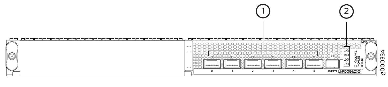
1 — Port LEDs | 2 — Lane display LEDs |
Figure 2 illustrates the port LED and lane LED displays for the MPC.
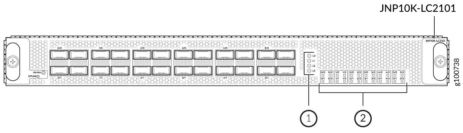
1 — Lane display LEDs | 2 — Port LEDs |
Figure 3 illustrates the port LED and lane LED displays for the MIC.
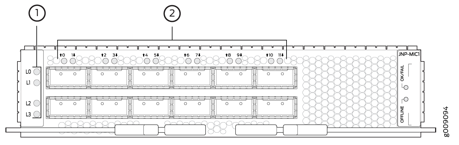
1 — Lane display LEDs | 2 — Port LEDs |
The following port LED display modes are defined:
-
Normal—The port status LED represents port state or a breakout port state. By default, the port status display mode is Normal.
-
Lane display—An array of lane status LEDs displays the status of each individual lane for the selected port. The lane display is ON when the software cycles through ports for lane status display. One port is selected at a time, and the display mode for that particular port switches to lane display mode. The other ports remain in normal display mode.
-
Port location—The port location mode is ON when a remote operator initiates a port location command for a port or a group of ports. The
request chassis port-ledcommand temporarily overrides periodic software port selection for the lane display; all ports on an interface card that are not selected for port location switch to Normal mode, and selected ports switch to port location mode. If only one port is selected for port location, then the corresponding lane LEDs are applicable. However, if the selected port is in breakout mode, then all lane LEDs are applicable. If not in breakout mode, only lane 0 LED displays the port status. If more than one port is selected for port location, then the lane LEDs are disabled.
The following factors trigger a change in the port LED color:
-
Change in the port state. For example, loss of signal (LOS) to no LOS, remote fault, or local fault
-
Pluggable insertion or removal
-
Change in configuration
-
Activation or deactivation of port location feature
-
Selection of breakout port for lane display
Ports with all individual links in Up state are skipped and are not considered for lane display, thereby reducing the time needed to cycle through all the ports.
Table 9 summarizes the state and color rules for the port LEDs. These rules help in determining the port LED color. When port location mode is activated, the port LED state or color can be determined from the Port Location ON column. If the breakout port is selected for the lane status display, then port LED state or color can be determined from the Lane Display column.
|
Pluggable Inserted |
Breakout Configuration State |
Explicitly Disabled |
Port State |
Normal |
Port Location ON |
Lane Display |
|---|---|---|---|---|---|---|
|
Yes |
No breakout |
No |
Up |
Green |
Blinking green |
- |
|
Yes |
No breakout |
No |
Down; loss of signal (LOS) detected |
Off |
Blinking green |
- |
|
Yes |
No breakout |
No |
Down; transceiver hardware failure |
Red |
Blinking red |
- |
|
Yes |
No breakout |
No |
Down; any other fault other than LOS and transceiver hardware failure |
Amber |
Blinking amber |
- |
|
ANY |
No breakout |
Yes |
Port disabled by CLI |
Amber |
Blinking amber |
- |
|
No |
Any |
No |
Anything except disabled port; however, transceiver not present |
Off |
Blinking green |
- |
|
Yes |
Breakout |
No |
All breakout ports are UP |
Green |
Blinking green |
Blinking green |
|
Yes |
Breakout |
No |
All breakout ports are down with LOS |
Off |
Blinking green |
Blinking green |
|
Yes |
Breakout |
No |
Hardware failure; transceiver initialization error at the port level (not individual lane) |
Red |
Blinking red |
Blinking red |
|
Yes |
Breakout |
Any |
In all other cases the port LED color is amber |
Amber |
Blinking amber |
Blinking amber |
The following factors trigger a change in the lane LED color:
-
A breakout port is selected for a lane display.
-
Port location mode is activated for a port on a given interface card.
Table 10 summarizes the state and color rules for the lane LEDs.
|
Pluggable Inserted |
Breakout Configuration State |
Explicitly Disabled |
Port State |
Order |
LED Color |
|---|---|---|---|---|---|
|
Yes |
Breakout |
No |
Up |
1 |
Green |
|
Yes |
Breakout |
No |
Down; loss of signal (LOS) detected |
2 |
Off |
|
Yes |
Breakout |
No |
Down; transceiver hardware failure |
3 |
Red |
|
Yes |
Breakout |
No |
Down; fault other than LOS and transceiver hardware failure |
4 |
Amber |
|
Yes |
Breakout |
Yes |
Breakout port is disabled in the CLI |
5 |
Amber |
Configure Slow Packet Forwarding Engine Alarm
On an M Series, MX Series, T Series, or SRX Series Firewall devices, the Packet Forwarding Engine might not send a resource acknowledgment message to the Routing Engine within a predetermined time of 360 seconds. This delay in receiving resource acknowledgment could be due to a slow or stuck Packet Forwarding Engine on the MX Series or SRX Series Firewall devices.
Starting with Junos OS Release 13.2R1 (also applicable in Junos OS
Releases 12.1R6, 12.2R5, 12.3R3, 13.1R2 and later), to display
the issue as an alarm in the show chassis
alarms command output and to append the
alarm to the system log messages file, you must enable the slow
Packet Forwarding Engine alarm on the router.
The following sections provide more information about the slow Packet Forwarding Engine alarm:
- Enable Slow Packet Forwarding Engine Alarm
- Disable Slow Packet Forwarding Engine Alarm
- Verify That the Alarm Output and System Log Messages are Updated
Enable Slow Packet Forwarding Engine Alarm
To enable the slow Packet Forwarding Engine alarm, perform the following steps:
By default, the slow Packet Forwarding Engine alarm is disabled.
Disable Slow Packet Forwarding Engine Alarm
To disable the slow Packet Forwarding Engine alarm, perform the following steps:
Verify That the Alarm Output and System Log Messages are Updated
Purpose
To verify that the output of the show
chassis alarms operational mode command
and the system log messages file are updated with
the slow Packet Forwarding Engine alarm when:
-
The
slow-pfe-alarmstatement is enabled in the[edit chassis]hierarchy. -
The Packet Forwarding Engine resource acknowledgment is not received by the Routing Engine within a predetermined time of 360 seconds.
Action
To check the output on an M Series, MX Series, T Series, or an SRX Series Firewall device:
Verify that the alarm is displayed in the output of the
show chassis alarmsoperational mode command.show chassis alarms
user@host> show chassis alarms
1 alarms currently active
Alarm time               Class  Description
2013-02-05 01:12:33 PST  Minor  Potential slow peers are: XDPC2
For field descriptions, see show chassis alarms.
Verify that the alarm is appended to the system log messages file.
/var/log/messages –
... Alarm set: RE color=YELLOW, class=CHASSIS, reason=Potential slow peers are: XDPC2
... Minor alarm set, Potential slow peers are: XDPC2
Meaning
The output of show chassis
alarms operational mode command and the
system log messages file are updated as expected
when the slow Packet Forwarding Engine alarm is
enabled and when the Packet Forwarding Engine
resource acknowledgment is not received by the
Routing engine within a predetermined time of 360
seconds.
User-Defined Alarm Relay Overview
The ACX Series router alarm contact port—labeled ALARM on the front panel—allows you to manage sensors and external devices connected to the router in remote unstaffed facilities.
Alarm contact port is not applicable on ACX5048 and ACX5096 routers.
Alarm Contact Port
The ACX Series router alarm contact port is a 15-pin D-type dry contact connector for alarms. The alarm contact port is used to generate LED alarms on the router and to turn external devices on or off. You can connect up to four input alarms and two output alarms. The alarm setting is open or closed.
Alarm Input
Alarm input provides dry contacts to connect to security sensors such as door or window monitors. The alarm input—open or closed—is sensed and reported to the management software. You can configure up to four alarm input relay ports (0 through 3) to operate as normally open or normally closed, and to trigger a red alarm condition or a yellow alarm condition or to ignore alarm conditions.
Alarm Output
Alarm output provides dry contacts to connect to external equipment, such as an audible or visual alarm that switches on or off–for example, a bell or a light. The four alarm output relay ports—0 through 3—are set up as follows:
Ports 0 and 1—These ports can be configured to trigger an alarm when the system temperature goes to the red alarm status and when an alarm input port is triggered.
Ports 2 and 3—These ports are not configured. They are used to indicate system major and minor alarms and are normally open. When a condition triggers an alarm, an alarm message is displayed.
To view the alarm input and output relay information, issue
the show chassis craft-interface command from the Junos
OS command line interface.
See Also
Configure Chassis Alarm Relays
On ACX Series routers, you can configure alarm relays that can trigger alarms and turn external devices on or off. For example, if the router heats up to more than the critical temperature, the output port is activated and a device connected to the output port—such as a fan—is turned on.
To configure conditions that trigger alarms, include
the relay statement with the input and output options at the [edit chassis alarm] hierarchy
level.
[edit chassis alarm]
relay
    input {
        port port-number {
            mode (close | open);
            trigger (ignore | red | yellow);
        }
    }
    output{
        port port-number {
            input-relay input-relay;
            mode (close | open);
            temperature;
        }
    }
The following output shows an example configuration of a chassis relay alarm:
[edit chassis alarm]
user@host# show
relay {
    input {
        port 1 {
            mode close;
            trigger red;
        }
    }
    output {
        port 0 {
            temperature;
        }
    }
}
Configure Chassis Alarm Input
The ACX Series router alarm contact port—labeled ALARM on the front panel—allows you to manage sensors and external devices connected to the router in remote unstaffed facilities. You can configure up to four alarm input ports (0 through 3) to operate as normally open or normally closed, and to trigger a red alarm condition or a yellow alarm condition or to ignore alarm conditions.
To configure an input alarm:
To view the alarm input relay information, issue the show
chassis alarms or show chassis craft-interface commands
from the Junos OS command line interface.
Configure Chassis Alarm Output
The ACX Series router alarm contact port—labeled ALARM on the front panel—allows you to manage sensors and external devices connected to the router in remote unstaffed facilities. You can configure up to two alarm output relay ports (0 and 1) to operate as normally open or normally closed, and to trigger an alarm when the system temperature goes to the red alarm status and when an alarm input port is triggered.
Ports 2 and 3 are not configured. They are used to indicate system major and minor alarms and are normally open. When a condition triggers an alarm, an alarm message is displayed, and the corresponding LED turns on.
To configure an output alarm:
To view the alarm output relay information, issue the show
chassis alarms or show chassis craft-interface command
from the Junos OS command line interface.
Configure Chassis Alarm Input and Output (ACX710 Routers)
The alarm interface port, an RJ45 port on the front panel of the ACX710 router, provides user-configurable input and output signals. You can configure the alarm input to receive alarm inputs from the external devices (such as sensors) connected to the router through the alarm port. You can configure the alarm output to relay the alarms in the router to external alarm devices (for example, bells and bulbs) connected to the router through the alarm port. You can configure up to three alarm inputs and one alarm output.
The router supports configuration of up to three alarm inputs and one alarm output, using the command alarm-port at the [edit chassis] hierarchy. You can configure the alarm input signals independent of the alarm output signal, and vice versa.
Pin Number of the Connector on the Device |
Signal Definition |
IN/OUT |
CLI Mapping |
|---|---|---|---|
1 |
ALARM_IN0_Sig |
IN |
port 1 |
2 |
ALARM_IN0_Return |
IN |
port 1 |
3 |
ALARM_IN1_Sig |
IN |
port 2 |
4 |
ALARM_IN2_Sig |
IN |
port 3 |
5 |
ALARM_IN1_Return |
IN |
port 2 |
6 |
ALARM_IN2_Return |
IN |
port 3 |
7 |
ALARM_OUT_Sig |
OUT |
port 1 |
8 |
ALARM_OUT_Return |
OUT |
port 1 |
To configure an alarm input:
To view the input alarms, by using the show chassis alarms command.
To configure an alarm output:
Specify the output port number by using the command
set chassis alarm-port output port port-number. The router supports only one output port (port number: 1).user@host# set chassis alarm-port output port 1
Set the administrative state of the alarm output as enabled.
user@host# set chassis alarm-port output port 1 admin-state enabled
Provide a description to the alarm input.
user@host# set chassis alarm-port input port 1 description alarm-output-description
Commit the configuration with the
commitcommand.
For more information, see alarm-port.
You can use the command show chassis craft-interface to view the alarm port configuration details.
user@router> show chassis craft-interface

System LED's on front panel:
-----------------------------
Fault LED :               On
Status LED :              Off
Operational LED :         On
Fan LED :                 Off

Alarm-port on front panel:
-----------------------------

Input port :                 1
         Active signal :    LOW
         Description :
         Admin state :      DISABLED
         Severity :         CRITICAL

Input port :                 2
         Active signal :    LOW
         Description :
         Admin state :      DISABLED
         Severity :         CRITICAL

Input port :                 3
         Active signal :    LOW
         Description :
         Admin state :      DISABLED
         Severity :         CRITICAL

Output port :                1
         Description :
         Admin state :      DISABLED