Overview of Multicast Forwarding with IGMP or MLD Snooping in an EVPN-MPLS Environment
To help optimize multicast traffic flow in an Ethernet VPN (EVPN) over MPLS environment, you can enable IGMP snooping for IPv4 multicast traffic or MLD snooping for IPv6 multicast traffic. In this environment, multicast receiver hosts in the EVPN instance (EVI) can be single-homed to one provider edge (PE) device or multihomed in all-active mode to multiple provider edge (PE) devices. For receivers that are multihomed to multiple PE devices, the peer PE devices synchronize IGMP or MLD state information. Receivers can be attached to PE devices in the EVI at the same site or at different sites.
Source hosts can be single-homed or multihomed to PE devices within the EVI in some supported use cases. For other use cases, the sources must reside outside the EVPN network in an external PIM domain, and each PE device that needs to receive multicast traffic connects through a Layer 3 interface to the PIM gateway router.
You can enable IGMP and MLD snooping for:
-
Multiple EVPN instances
-
Specific bridge domains or VLANs in an EVPN instance
-
All bridge domains or VLANs within an EVPN virtual switch instance (on supporting devices)
Devices in this environment can forward multicast traffic within a bridge domain or VLAN, and route multicast traffic across bridge domains or VLANs at Layer 3 using IRB interfaces.
Benefits of Multicast Forwarding with IGMP or MLD Snooping in an EVPN-MPLS Environment
-
In an environment with significant multicast traffic, IGMP or MLD snooping constrains multicast traffic in a broadcast domain or VLAN to interested receivers and multicast devices, which conserves network bandwidth.
-
Synchronizing IGMP or MLD state among all EVPN PE devices for multihomed receivers ensures that all subscribed listeners receive multicast traffic, even in cases such as the following:
-
IGMP or MLD membership reports for a multicast group might arrive on a PE device that is not the Ethernet segment’s designated forwarder (DF).
-
An IGMP or MLD message to leave a multicast group arrives at a different PE device than the PE device where the corresponding join message for the group was received.
-
Multicast Forwarding with IGMP or MLD Snooping in Single-homed or Multihomed Ethernet Segments
Hosts in the network send IGMP or MLD reports expressing interest in particular multicast groups from IPv4 multicast sources (using IGMP) or IPv6 multicast sources (using MLD). PE devices with IGMP or MLD snooping enabled listen to (snoop) IGMP or MLD packets. The PEs then use the snooped information to establish multicast routes that only forward traffic to interested receivers for a multicast group.
For redundancy, your network can include multicast receivers multihomed to a set of peer PE devices in all-active mode. In some use cases, sources can be multihomed to peer PE devices within the EVI. If you enable snooping on all PE devices in the EVI, the multihomed peer PE devices synchronize the IGMP or MLD state among themselves so multicast traffic can successfully reach all listeners.
The next sections describe the IGMP and MLD group membership report processing and subsequent multicast traffic flow in this environment.
- IGMP or MLD State Synchronization Among Multihoming Peer PE Devices
- Leave Message Processing with Multihoming Peer PE Devices
- IGMP or MLD Versions and Supported Group Membership Report Modes
- How Multicast Traffic Forwarding Works with Single-homed or Multihomed Receivers
IGMP or MLD State Synchronization Among Multihoming Peer PE Devices
In an EVI with receivers that are multihomed to multiple PE devices, corresponding IGMP or MLD join and leave messages for multicast group management might not be sent to the same PE device. As a result, all the PE devices must synchronize and share IGMP and MLD state.
PE devices with snooping enabled in this environment exchange BGP EVPN Type 7 (Join Sync Route) and Type 8 (Leave Synch Route) network layer reachability information (NLRI) to synchronize IGMP or MLD membership reports received on multihomed interfaces. The network must use multihoming in all-active mode.
The advertised EVPN Type 7 and Type 8 routes also carry EVI route target extended community attributes associated with multihomed EVIs to support multiple EVPN routing instances simultaneously. Only PE devices that share the same Ethernet segment ID import these routes.
PE devices serving single-homed hosts do not need to advertise or import EVPN Type 7 and Type 8 routes. However, to save bandwidth on the access side by only forwarding multicast traffic to interested receivers, you should also configure IGMP or MLD snooping in this case.
Due to platform-specific differences among the devices that support multicast with IGMP or MLD snooping in an EVPN-MPLS multihomed environment, we offer slightly different solutions on the supporting platforms in certain use cases.
EX9200 Switches, MX Series Routers, and vMX Routers—Multicast State Synchronization for Multihoming in EVPN-MPLS
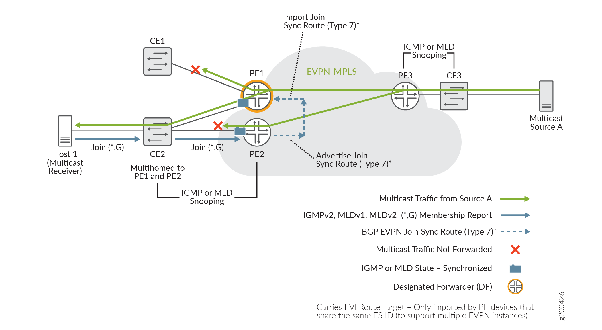
EX9200 switches, MX Series routers, and vMX routers support EVPN-MPLS multihoming with IGMP and MLD snooping and synchronize the IGMP or MLD state as shown in Figure 1.

This example topology includes a multicast source (Multicast Source A) behind PE3 by way of customer edge device CE3, and a multicast receiver Host 1 behind CE2 that is multihomed to PE1 and PE2.
Multihoming peer PE2 receives a membership request from Host 1, and advertises the EVPN Type 7 Join Sync Route to the EVPN core. PE1 imports the Type 7 route to synchronize the IGMP or MLD state among the PE devices to which the receiver is multihomed (PE1 and PE2). When both PE1 and PE2 receive multicast traffic from the EVPN-MPLS network, only PE1, the designated forwarder (DF), forwards the traffic to CE2 to reach the interested listener on Host 1. PE1 doesn’t forward the traffic to CE1, which has no interested listeners.
EX9200 switches, MX Series routers and vMX routers support IGMP and MLD snooping with EVPN-MPLS multihoming under the following constraints:
-
All multihoming peer PE devices must support BGP EVPN Type 7 Join Sync Routes and Type 8 Leave Sync Routes.
-
You can configure IGMP snooping or MLD snooping for multiple routing instances of type
evpnor typevirtual-switch. -
You must configure all bridge domains or VLANs with multicast sources and receivers on all PE devices in the EVI.
-
You must configure MX Series PE devices in enhanced IP Network Services mode. (See Network Services Mode Overview.)
-
Routing multicast traffic between bridge domains or VLANs is through IRB interfaces only. You can’t have a topology that uses an external multicast router for intersubnet multicast routing in this environment. (Using an external multicast router instead of IRB interfaces is an available solution with EVPN-VXLAN networks.)
-
Multicast sources and receivers must be within the EVI. Receiving or forwarding multicast traffic from or to devices outside of this environment using a PIM gateway is not supported.
-
Selective multicast forwarding (advertising EVPN Type 6 Selective Multicast Ethernet Tag (SMET) routes for forwarding only to interested receivers) in the EVPN core is not supported.
-
IGMP and MLD snooping are not supported with point-to-multipoint (P2MP) multipoint LDP/RSVP replication; only ingress replication is supported.
ACX Series Routers—Multicast State Synchronization for Multihoming in EVPN-MPLS
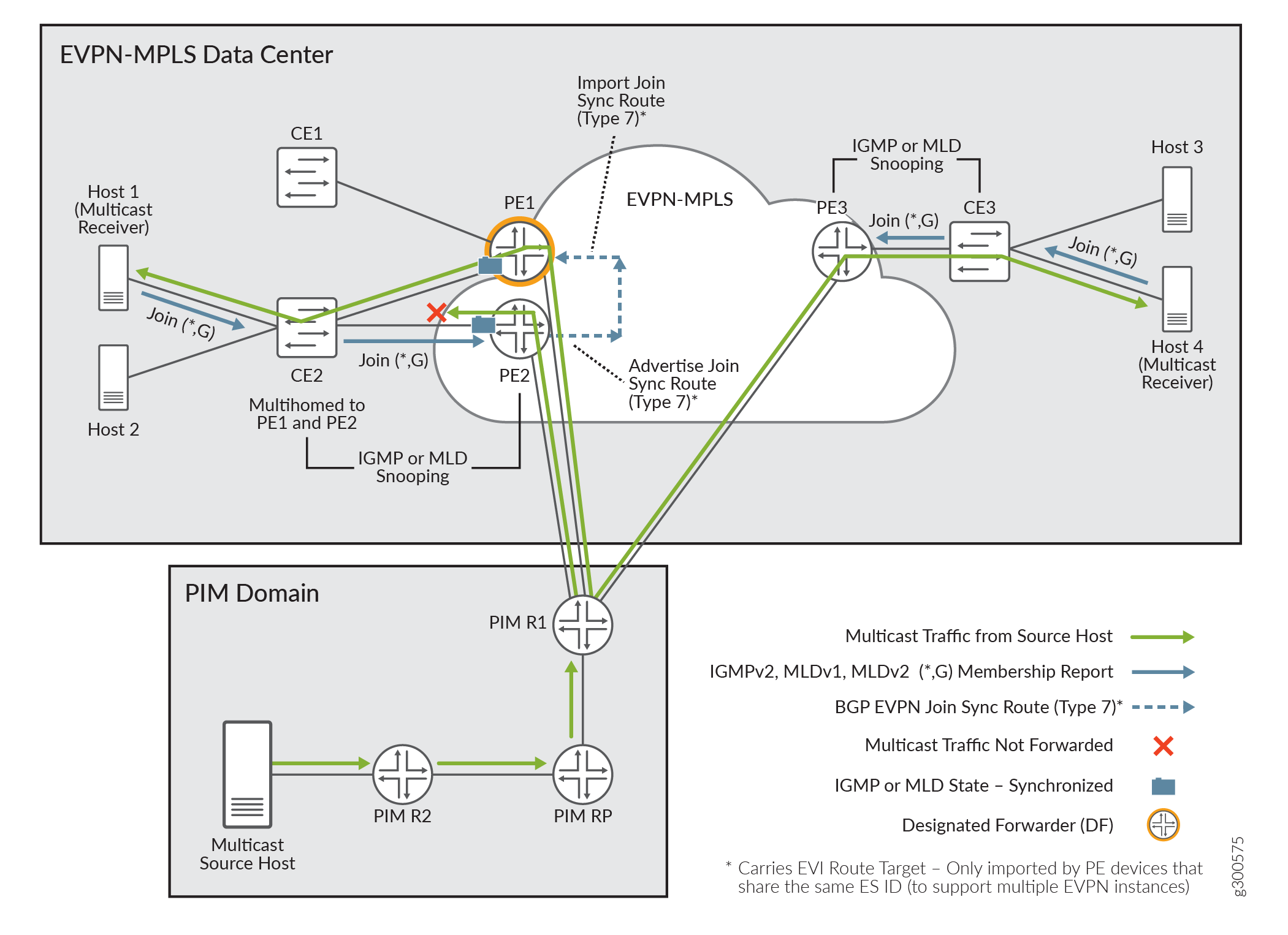
On ACX Series routers with EVPN-MPLS multihoming and IGMP and MLD snooping, to support routing multicast traffic across bridge domains or VLANs (intersubnet multicast), any multicast sources must be outside of the EVPN-MPLS datacenter in a Layer 3 PIM domain. (An ACX Series router can’t act as a multicast first-hop router, so multicast sources can’t be connected to ACX routers for intersubnet routing.) Each ACX Series PE device must receive the multicast source traffic through a Layer 3 interface connected to the external PIM domain gateway router. See Figure 2. If your EVPN-MPLS datacenter only needs to forward multicast traffic within bridge domains or VLANs (intrasubnet multicast), you can use a topology similar to Figure 1 with sources inside the datacenter.
In both the intrasubnet and intersubnet use cases, IGMP or MLD state synchronization among multihoming peer PE devices works the same as the EVPN-MPLS multicast with multihoming solutions for other platforms.

The example topology in Figure 2 can support both intrasubnet and intersubnet multicast traffic because it includes a multicast source (Multicast Source Host) in an external PIM domain, and Layer 3 connections from the PE devices to the external PIM gateway router. Multicast receiver Host 1 behind CE2 is multihomed to peer PE devices PE1 and PE2. Single-homed multicast receiver Host 4 connects to PE3 by way of CE3. All of the EVPN PEs serving multicast receivers have IGMP (or MLD) snooping enabled. To optimize multicast forwarding on the access side, you can also enable IGMP or MLD snooping on the CE devices (if supported).
Multihoming peer PE2 receives a membership request from Host 1, and advertises the EVPN Type 7 Join Sync Route to the EVPN core. PE1 imports the Type 7 route to synchronize the IGMP or MLD state among the PE devices to which the receiver is multihomed (PE1 and PE2). PE3 receives a membership request from single-homed Host 4, and with no multihoming peers, doesn’t need to synchronize IGMP or MLD state information.
ACX Series routers support IGMP and MLD snooping with EVPN-MPLS multihoming under the following constraints:
-
All multihomed peer PE devices must support BGP EVPN Type 7 Join Sync Routes and Type 8 Leave Sync Routes.
-
You can configure IGMP snooping or MLD snooping for one or more routing instances of type
evpnonly. -
You must configure all multicast bridge domains or VLANs on all PE devices in the EVI.
-
Routing multicast traffic between bridge domains or VLANs is through IRB interfaces only. You can’t have a topology that uses an external multicast router for intersubnet multicast routing instead of IRB interfaces. (Using an external multicast router instead of IRB interfaces is an available solution with EVPN-VXLAN networks on some platforms.)
-
As mentioned previously, to support intersubnet multicast traffic routing, multicast sources must reside outside the data center in an external PIM domain. All PEs connect to the PIM gateway and send PIM join messages through the PIM rendezvous point (RP). The PIM gateway forwards traffic for the group to all PE devices.
Note:In this environment, multicast sources can be within the EVI only when the multicast traffic for a group is all within the same bridge domain or VLAN (intrasubnet multicast only).
-
Selective multicast forwarding (advertising EVPN Type 6 Selective Multicast Ethernet Tag (SMET) routes for forwarding only to interested receivers) in the EVPN core is not supported.
-
IGMP and MLD snooping are not supported with point-to-multipoint (P2MP) multipoint LDP/RSVP replication; only ingress replication is supported.
Leave Message Processing with Multihoming Peer PE Devices
Processing leave messages and membership route withdrawals in a multihomed environment is more complicated when the leave message is not received by the same PE device that processed the join message. PE devices use BGP EVPN Type 8 routes to facilitate leave operations as follows:
-
A PE device that receives an IGMP or MLD leave message for a group advertises a Type 8 route. Other PE devices import the Type 8 route.
-
The PE device that advertised the Type 8 route originates a membership query for any remaining group members, and starts a leave timer. The other PE devices that imported the Type 8 route likewise start a leave timer.
-
If no join membership reports are received by the time the timer expires, the PE device that advertised the Type 7 route withdraws the Type 7 route. The PE device that originated the Type 8 route withdraws the Type 8 route.
IGMP or MLD Versions and Supported Group Membership Report Modes
Any-source multicast (ASM) or (*,G) group membership mode includes all sources for a multicast group's traffic. Source-specific multicast (SSM) or (S,G) mode handles multicast group membership based on a specific source and the group address.
By default, PE devices in this EVPN-MPLS environment support ASM mode with IGMPv2, IGMPv3, MLDv1, and MLDv2 under certain conditions. You can alternatively configure PE devices to process only SSM membership reports with IGMPv3 and MLDv2 in environments that support intersubnet traffic. PE devices don’t support processing both ASM and SSM membership reports at the same time.
Table 1 summarizes membership report modes supported with each IGMP or MLD version. IGMPv1 is not supported with EVPN-MPLS multicast.
|
IGMP or MLD Version |
ASM (*,G) Only |
SSM (S,G) Only |
ASM (*,G) + SSM (S,G) |
|---|---|---|---|
|
IGMPv1 |
- |
- |
- |
|
IGMPv2 |
Yes |
No |
No |
|
IGMPv3 |
Yes (Only on ACX Series) |
Yes (Only on ACX Series, when explicitly configured) |
No |
|
MLDv1 |
Yes |
No |
No |
|
MLDv2 |
Yes (ACX Series: Only with MLDv2 configured on all interfaces that receive multicast traffic) |
Yes (Only when explicitly configured) |
No |
The next sections give more details on platform-specific PE device behavior when processing IGMP or MLD membership reports.
ASM and SSM Mode Behavior on EX9200 Switches, MX Series Routers, and vMX Routers
By default, the EVPN-MPLS network can process ASM (*,G) membership reports with IGMPv2, MLDv1, and MLDv2. If the network has hosts sending both MLDv1 and MLDv2 ASM reports for a given group, PE devices will process MLDv1 and MLDv2 reports for the group as MLDv1 membership reports. They drop and do not process any SSM reports.
You can alternatively enable IGMP snooping or MLD snooping with
the evpn-ssm-reports-only option to explicitly configure
PEs to accept and process SSM (S,G) membership reports with MLDv2.
With this option, PEs only accept SSM reports, and drop and do not
process any ASM reports.
-
You can enable SSM-only processing for one or more bridge domains in the EVI.
-
When enabling this option for a virtual switch, this behavior applies to all bridge domains in the virtual switch instance.
ASM and SSM Mode Behavior on ACX Series Routers
With IGMP snooping enabled and multicast traffic flow is within bridge domains or VLANs (intrasubnet):
-
By default, PE devices process IGMPv2 ASM (*,G) membership reports, but discard any IGMPv3 reports.
-
If you configure all interfaces that receive multicast traffic with IGMPv3, PE devices can process IGMPv3 reports in ASM (*,G) mode, but they discard IGMPv3 SSM (S,G) reports.
With MLD snooping enabled and multicast traffic flow is within bridge domains or VLANs (intrasubnet):
-
By default, PE devices can process MLDv1 ASM (*,G) membership reports but discard any MLDv2 reports.
-
If you configure all interfaces that receive multicast traffic with MLDv2, PE devices can process both MLDv1 and MLDv2 reports in ASM (*,G) mode, but they discard MLDv2 SSM (S,G) reports.
With IGMP snooping or MLD snooping enabled and routing multicast traffic between bridge domains or VLANs (intersubnet):
-
With IGMP snooping, by default, PE devices process IGMPv2 and IGMPv3 membership reports in ASM (*,G) mode. They discard IGMPv3 SSM (S,G) reports.
-
With MLD snooping, by default, PE devices process MLDv1 and MLDv2 membership reports in ASM (*,G) mode. They discard MLDv2 SSM (S,G) reports.
-
If you enable IGMP snooping or MLD snooping with IGMPv3 or MLDv2 and the SSM-only processing option,
evpn-ssm-reports-only, then PE devices process IGMPv3 or MLDv2 reports as SSM (S,G) only. They discard any ASM (*,G) reports.In this case, for best results, we recommend that you configure IGMPv3 or MLDv2 on all IRB interfaces that do intersubnet routing.
How Multicast Traffic Forwarding Works with Single-homed or Multihomed Receivers
In an EVPN-MPLS network where hosts might be multihomed to more than one PE device, when a bridge domain (or VLAN) is configured on a PE device, the PE device signals a BGP EVPN Type 3 (Inclusive Multicast Ethernet Tag [IMET]) route to the other PE devices in the instance to build a core multicast replication tree for each configured bridge domain.
A PE device receiving multicast traffic to be forwarded is referred to as the ingress PE device. To ensure multicast traffic reaches all remote PE devices in the EVI, the ingress PE device uses the IMET routing information with ingress replication in the EVPN core, replicating and flooding the packets on the EVPN tunnels to all of the other PE devices (or external edge routers) in the EVI that might need to forward the traffic. IGMP or MLD snooping is not performed in the EVPN core.
When the multicast source is outside the EVPN-MPLS network in an external PIM domain (as it is in the implementation for ACX Series routers), each PE device receives the source traffic directly from the configured Layer 3 interfaces to the PIM gateway router, and not by way of IMET signaling in the EVPN core.
With IGMP or MLD snooping enabled:
-
When a multihoming PE device receives multicast traffic and it is the DF for an interested receiver for the multicast group, the PE device forwards the traffic.
-
When a multihoming PE device receives multicast traffic and it is not the DF for any interested receivers, the PE device does not forward the traffic.
-
On the access side, upon receiving multicast data from the EVPN core, PE devices selectively forward the multicast traffic only to interested receivers. Single-homing PE devices use learned IGMP or MLD snooping information, and multihoming PE devices use both IGMP or MLD snooping information and EVPN Type 7 routes.
For example, let’s look again at the use case in Figure 3 with sources and receivers all inside the EVPN-MPLS network.

PE3 is the ingress PE device for Multicast Source A and forwards the multicast traffic into the EVPN core. PE1 and PE2 receive the multicast traffic from the EVPN core. Host 1 is a multicast receiver that is multihomed to PE1 and PE2 by way of customer edge device CE2. PE1 and PE2 have synchronized IGMP or MLD state information about receiver Host 1. The PEs forward the traffic as follows:
-
Because PE1 is currently the elected DF for Host 1, PE1 forwards the data toward Host 1.
-
Based on the IGMP or MLD snooping information and imported EVPN Type 7 routing information, PE1 doesn’t forward the data toward CE1 because CE1 doesn’t have any interested receivers.
-
PE2 is not the DF, so PE2 doesn’t forward the traffic toward Host 1, and avoids sending a duplicate stream.
Also consider the use case in Figure 4 for ACX Series routers with EVPN-MPLS multihoming that supports multicast across bridge domains or VLANs, where the sources must be outside the EVPN network in an external PIM domain.

PE1, PE2, and PE3 all have Layer 3 connections to the PIM gateway router PIM R1, and all PE devices are ingress PEs. In this case, all PEs receive the multicast source traffic from the source through PIM R1. Host 3 and Host 4 are single-homed to PE3 by way of CE3. Host 1 is a multicast receiver that is multihomed to PE1 and PE2 through CE2. The PEs forward the traffic as follows:
-
Host 4 is a multicast receiver, so PE3 sends the traffic to CE3 to reach Host 4.
-
Host 3 isn’t a multicast receiver, so with snooping enabled, CE3 doesn’t forward the traffic to Host 3.
-
PE1 and PE2 have synchronized IGMP or MLD state information about receiver Host 1, and as peer PE devices, they behave in the same way as the use case with all sources and receivers inside the EVPN-MPLS network:
-
As the elected DF for Host 1, PE1 forwards the data to Host 1. PE2 is not the DF and doesn’t send a duplicate stream to Host 1.
-
Based on the IGMP or MLD snooping information and imported EVPN Type 7 routing information, PE1 doesn’t forward the data toward CE1 because CE1 doesn’t have any interested receivers.
-
IGMP or MLD Snooping with Multicast Forwarding Between Bridge Domains or VLANs Using IRB Interfaces
For multicast forwarding between bridge domains or VLANs in this environment, PE devices use Protocol Independent Multicast (PIM) in distributed designated router (DDR) mode on IRB interfaces.
-
You must configure IRB interfaces on all PE devices in the EVI that need to route multicast traffic locally between bridge domains or VLANs on the device.
Note:If you configured a bridge domain (or VLAN) and an IRB interface on all PE devices, and an IRB interface is down on a PE device, traffic routing between bridge domains (or VLANs) for receivers served by that IRB will be impacted.
-
To route Layer 3 multicast traffic between bridge domains or VLANs, you must also configure PIM distributed designated router (DDR) mode on all participating IRB interfaces. (See distributed-dr for more details.) PIM passive mode is not supported.
The IRB interfaces on the PE devices route multicast traffic between bridge domains or VLANs as follows:
-
Upon receiving multicast traffic on an IRB interface from a multicast source, the PE device routes the traffic to any IRBs that have PIM enabled and are configured with bridge domains or VLANs that have interested local receivers for the multicast group.
-
In PIM DDR mode, the IRB interfaces route multicast traffic to local receivers whether or not the IRB is the elected PIM designated router (DR).
-
To prevent multicast traffic duplication, IRB-routed multicast traffic is not forwarded back out to the EVPN core.
The IRB interfaces route ingress multicast traffic between bridge domains or VLANs toward receivers in the same way whether the multicast source is inside the EVPN-MPLS network or is in an external PIM domain.
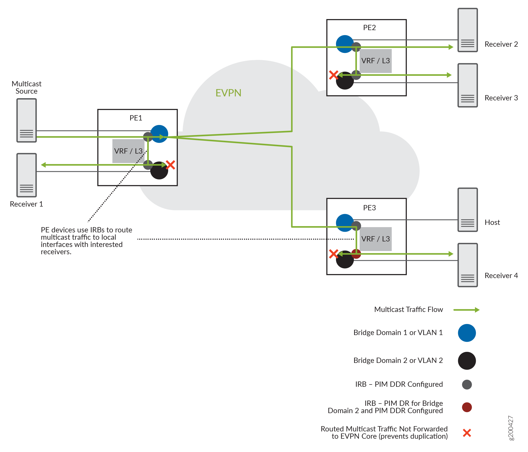
For example, Figure 5 shows PE devices with IRB interfaces where the PE devices receive source traffic through the EVPN-MPLS network.
ACX Series routers support do not support having multicast sources within the EVPN-MPLS network for routing inter-VLAN multicast traffic. See Figure 6 instead.

In this use case, the EVPN instance has three PE devices, PE1, PE2, and PE3, with IRB interfaces configured on each PE device for two bridge domains or VLANs. The multicast source on bridge domain 1 (VLAN 1) sends multicast traffic to PE1, and PE1 uses inclusive multicast forwarding with ingress replication to forward the traffic to the EVPN core to reach other PE devices with interested receivers. PE1 routes the traffic locally to interested receivers on bridge domain 2 (VLAN 2) through the IRB interfaces, even though PE3 is the PIM DR for bridge domain 2 (VLAN 2). The IRB interfaces on all PE devices that route traffic to receivers on bridge domain 2 (VLAN 2) do not forward the routed traffic back out into the EVPN core. PE2 receives the multicast traffic from the EVPN core and forwards or locally routes the traffic on each bridge domain (or VLAN) that has interested receivers. PE3 routes the traffic locally to bridge domain 2 only, because there are no interested receivers on bridge domain 1 (or VLAN 1).
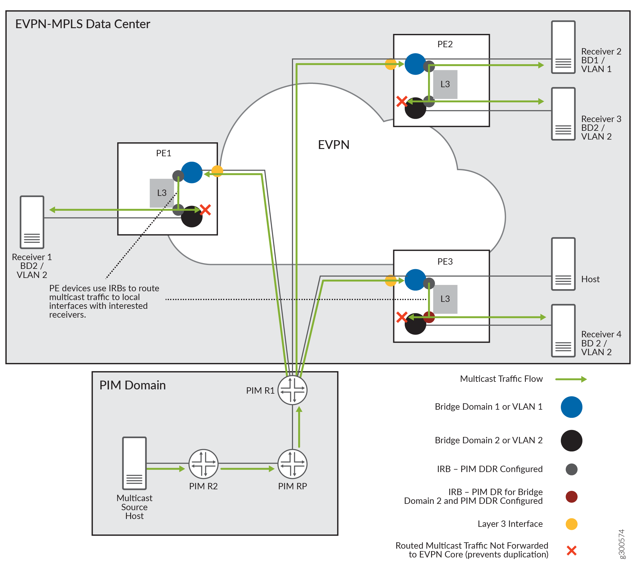
Figure 6 shows the PE devices similarly configured with IRB interfaces in DDR mode, but each of the PE devices receives the multicast traffic from an external source through Layer 3 interfaces connected to the PIM gateway router. This is the use case supported on ACX Series routers for routing inter-VLAN multicast traffic in an EVPN-MPLS network.

In this use case, PE1, PE2, and PE3 also have IRB interfaces configured on each PE device for two bridge domains or VLANs. Each PE might have interested receivers, so each one has a Layer 3 connection to the source PIM domain and receives the multicast traffic on BD1 (VLAN 1). PE1 and PE3 each route the traffic locally through the IRB interfaces to their receivers (Receiver 1 and Receiver 4) on BD2 (VLAN 2), and PE2 does the same for its Receiver 3 on BD2, even though PE3 is the PIM DR for BD2 (VLAN 2). PE2 also forwards the traffic locally to Receiver 2 on BD1 (VLAN 1). The PE devices don’t send source traffic out into the EVPN core at all in this model.
