Damping Interfaces
You (the network administrator) can configure damping to reduce the advertisement of physical interface transitions between up and down states.
Physical Interface Damping Overview
Physical interface damping limits the advertisement of the up-and-down transitions (flapping) on an interface. Each time a transition occurs, the interface state is changed, which generates an advertisement to the upper-level routing protocols. Damping helps reduce the number of these advertisements.
From the viewpoint of network deployment, physical interface flaps fall into the following categories:
-
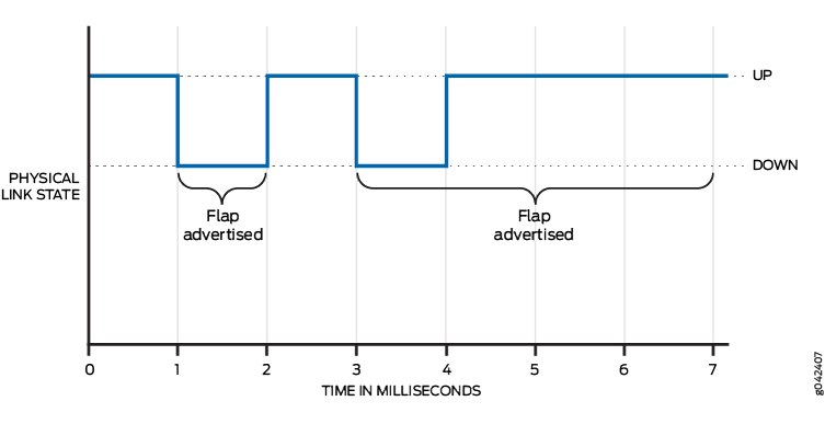
Nearly instantaneous multiple flaps of short duration (ms)
-
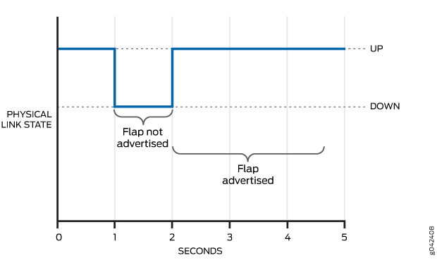
Periodic flaps of long duration (seconds)
Figure 1 is used to describe these types of interface flaps and the damping configuration that you can use in each case.

We recommend that you use similar damping configurations on both ends of the physical interface. Configuring interface damping on one end and not configuring interface damping on the other end can result in undesired behavior.
The types of interface damping depend upon the transition time length.
- Damping Overview for Shorter Physical Interface Transitions
- Damping Overview for Longer Physical Interface Transitions
Damping Overview for Shorter Physical Interface Transitions
Figure 1 shows two routers with two transport devices between them. If a redundant link between the two transport devices fails, Junos OS Evolved performs link switching. Link switching takes a number of milliseconds. As shown in Figure 2, during switching, both device interfaces might encounter multiple flaps with an up-and-down duration of several milliseconds. These multiple flaps, if advertised to the upper-level routing protocols, might result in undesired route updates. This is why you might want to damp these interface flaps. Damping is suitable only with routing protocols.
For shorter physical interface transitions, you configure interface damping with the
hold-time statement on the interface. The hold timer enables
interface damping by not advertising interface transitions until the hold timer
duration has passed. When a hold-down timer is configured and the interface goes
from up to down, the down hold-time timer is triggered. Every interface transition
that occurs during the hold time is ignored. When the timer expires and the
interface state is still down, then the router begins to advertise the
interface as being down. Similarly, when a hold-up timer is configured and an
interface goes from down to up, the up hold-time timer is triggered. Every interface
transition that occurs during the hold time is ignored. When the timer expires and
the interface state is still up, then the router begins to advertise the
interface as being up.

Damping Overview for Longer Physical Interface Transitions
When the link between a router interface and the transport devices is not stable, this can lead to periodic flapping, as shown in Figure 3. Flaps occur in the order of seconds or more, with an up-and-down flap duration in the order of a second or more. In this case, using the hold timer feature might not produce optimal results because it cannot suppress the relatively longer and repeated interface flaps. Increasing the hold-time duration to seconds still allows the system to send route updates on the flapping interface. Increasing the duration therefore fails to suppress periodically flapping interfaces on the system.

For longer periodic interface flaps, configure interface damping with the
damping statement on the interface. This damping method uses an
exponential back-off algorithm to suppress interface up-and-down event reporting to
the upper-level protocols. Every time an interface goes down, Junos OS Evolved adds a penalty to the interface penalty counter.
If at some point the accumulated penalty exceeds the suppress level, Junos OS Evolved places the interface in the suppress state. In
this case, Junos OS Evolved does not report further interface link
up-and-down events to the upper-level protocols.
The penalty added on every interface flap is 1000. At all times, the interface
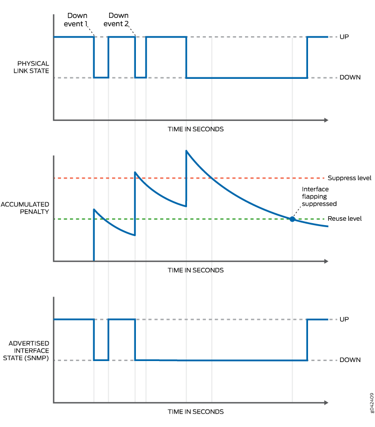
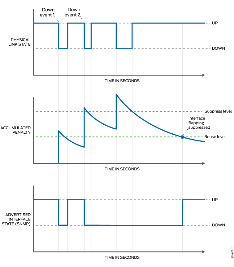
penalty counter follows an exponential decay process. Figure 4 and Figure 5 show the decay process
as it applies to recovery when the physical level link is down or up. As soon as the
accumulated penalty reaches the lower boundary of the reuse level, the interface is
marked as unsuppressed, and further changes in the interface link state are again
reported to the upper-level protocols. You use the max-suppress
option to configure the maximum time for restricting the accumulation of the penalty
beyond the value of the maximum penalty. The value of the maximum penalty is
calculated by the software. The maximum penalty corresponds to the time it would
take max-suppress to decay and reach the reuse level. The penalty continues to decay
after crossing the reuse level.
Figure 4 and Figure 5 show the accumulated penalty and the decay over time as a curve. Whenever the penalty is below the reuse level and the physical level link changes state, state changes are advertised to the system and cause SNMP state changes.
Figure 4 shows the penalty dropping below the reuse level when the physical link is down. The system is notified of a state change only after the physical level link transitions to up.

Figure 5 shows the penalty dropping below the reuse level when the physical link is up. The system is notified of a state change immediately.

The QFX10002-72Q and QFX10002-36Q switches do not support hold-time
down of less than 1 second on 100G interfaces. The recommended
hold-time down is 3 seconds.
Configure Damping of Shorter Physical Interface Transitions
By default, when an interface changes from up to down or from down to up, this transition is advertised immediately to the hardware and Junos OS Evolved. In some situations, you might want to damp interface transitions.
Damping the interface means not advertising the interface’s transition until a certain period of time has passed, called the hold-time. When the interface goes from up to down, the down hold-time timer is triggered. Every interface transition that occurs during the hold time is ignored. If the timer expires and the interface state is still down, then the router begins to advertise the interface as being down. Similarly, when an interface goes from down to up, the up hold-time timer is triggered. Every interface transition that occurs during the hold time is ignored. If the timer expires and the interface state is still up, then the router begins to advertise the interface as being up.
To configure damping of shorter physical interface transitions in ms:
The hold time can be a value from 0 through 4,294,967,295 milliseconds. The default value is 0, which means that interface transitions are not damped. Junos OS Evolved advertises the transition within 100 milliseconds of the time value you specify.
For most Ethernet interfaces, Junos OS Evolved implements hold timers using a one-second polling algorithm. For 1-port, 2-port, and 4-port Gigabit Ethernet interfaces with small form-factor pluggable (SFP) transceivers, hold timers are interrupt driven.
The hold-time option is not available for controller interfaces.
Configure Damping of Aggregated Ethernet Interface Transitions
By default, when an interface changes from up to down or from down to up, this transition is advertised immediately to the hardware and Junos OS Evolved. In some situations, you might want to damp interface transitions.
Damping the interface means not advertising the interface’s transition until a certain period of time has passed, called the hold-time. When the interface goes from up to down, the down hold-time timer is triggered. Every interface transition that occurs during the hold time is ignored. If the timer expires and the interface state is still down, then the router begins to advertise the interface as being down. Similarly, when an interface goes from down to up, the up hold-time timer is triggered. Every interface transition that occurs during the hold time is ignored. If the timer expires and the interface state is still up, then the router begins to advertise the interface as being up.
To configure damping of aggregated ethernet interface transitions in milliseconds:
The hold time can be a value from 0 through 4,294,967,295 milliseconds. The default value is 0, which means that interface transitions are not damped. Junos OS Evolved advertises the transition within 100 milliseconds of the time value you specify.
For most Ethernet interfaces, Junos OS Evolved implements hold timers using a one-second polling algorithm. For 1-port, 2-port, and 4-port Gigabit Ethernet interfaces with small form-factor pluggable (SFP) transceivers, hold timers are interrupt driven.
You can specify the hold-time value on aggregated ethernet interfaces. When you configure hold-timer for ae- interfaces, we recommend not to configure the hold-time for member links.
The hold-time option is not available for controller
interfaces.
Configure Damping of Longer Physical Interface Transitions
Physical interface damping limits the advertisement of the up-and-down transitions (flapping) on an interface. An unstable link between a router Interface and the transport devices can lead to periodic flapping. Longer flaps occur with a period of about five seconds or more, with an up-and-down duration of one second.
For these longer periodic interface flaps, configure interface damping with the
damping statement on the interface. This damping method uses an
exponential back-off algorithm to suppress interface up-and-down event reporting to the
upper-level protocols. Every time an interface goes down, a penalty is added to the
interface penalty counter. If at some point the accumulated penalty exceeds the suppress
level max-suppress, the interface is placed in the suppress state, and
further interface state up-and-down transitions are not reported to the upper-level
protocols.
You can view the damping parameters with the show interfaces extensive
command.
Use Physical interface damping to confirm platform and release support for specific features.
To configure damping of longer physical interface transitions:
