Example: Protecting Against Address Spoofing and Layer 2 DoS Attacks
You can configure DHCP snooping, dynamic ARP inspection (DAI), and MAC limiting on the access interfaces of a switch to protect the switch and the Ethernet LAN against address spoofing and Layer 2 denial-of-service (DoS) attacks. To obtain the basic settings for these features, you can use the switch's default configuration for port security, configure the MAC limit, and enable DHCP snooping and DAI on a VLAN. You can configure these features when the DHCP server is connected to a switch that is different from the one to which the DHCP clients (network devices) are connected.
This example describes how to configure port security features on a switch whose hosts obtain IP addresses and lease times from a DHCP server connected to a second switch:
Requirements
This example uses the following hardware and software components:
One EX Series switch or QFX3500 switch—Switch 1 in this example.
An additional EX Series switch or QFX3500 switch—Switch 2 in this example. You do not configure port security on this second switch.
Junos OS Release 9.0 or later for EX Series switches or Junos OS Release 12.1 or later for the QFX Series.
A DHCP server connected to Switch 2. You use the server to provide IP addresses to network devices connected to Switch 1.
At least two network devices (hosts) that you connect to access interfaces on Switch 1. These devices are DHCP clients.
Before you configure DHCP snooping, DAI, and MAC limiting port security features, be sure you have:
Connected the DHCP server to Switch 2.
Configured a VLAN on Switch 1. See the task for your platform:
Overview and Topology
Ethernet LANs are vulnerable to address spoofing and DoS attacks on network devices. To protect the devices from such attacks, you can configure:
DHCP snooping to validate DHCP server messages
DAI to protect against ARP spoofing
MAC limiting to constrain the number of MAC addresses the switch adds to its MAC address cache
This example shows how to configure these port security features on Switch 1. Switch 1 is connected to another switch (Switch 2), which is not configured with port security features. Switch 2 is connected to a DHCP server (see Figure 1.) Network devices (hosts) that are connected to Switch 1 send requests for IP addresses (these network devices are DHCP clients). Those requests are transmitted from Switch 1 to Switch 2 and then to the DHCP server connected to Switch 2. Responses to the requests are transmitted along the reverse path of the one followed by the requests.
The setup for this example includes the VLAN employee-vlan on both switches.
Figure 1 shows the network topology for the example.
Topology
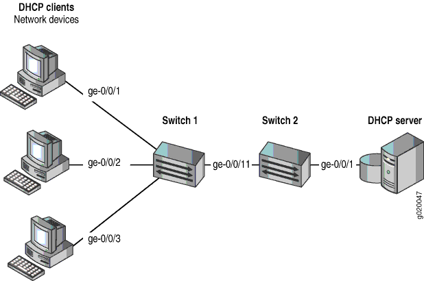
The components of the topology for this example are shown in Table 1.
| Properties | Settings |
|---|---|
Switch hardware |
One EX Series switch or one QFX3500 switch (Switch 1), and an additional EX Series switch or QFX3500 switch (Switch 2) |
VLAN name and ID |
|
VLAN subnets |
|
Trunk interface on both switches |
ge-0/0/11 |
Access interfaces on Switch 1 |
ge-0/0/1, ge-0/0/2, and ge-0/0/3 |
Access interface on Switch 2 |
ge-0/0/1 |
Interface for DHCP server |
ge-0/0/1 on Switch 2 |
Switch 1 is initially configured with the default port security setup. In the default configuration on the switch:
Secure port access is activated on the switch.
The switch does not drop any packets, which is the default setting.
DHCP snooping and DAI are disabled on all VLANs.
All access interfaces are untrusted and trunk interfaces are trusted; these are the default settings.
In the configuration tasks for this example, you configure a VLAN on both switches.
In addition to configuring the VLAN, you enable DHCP snooping on Switch 1. In this example,
you also enable DAI and a MAC limit of 5 on Switch 1.
Because the interface that connects Switch 2 to Switch 1 is a trunk interface, you do not need to configure this interface to be trusted. As noted above, trunk interfaces are automatically trusted, so DHCP messages coming from the DHCP server to Switch 2 and then on to Switch 1 are trusted.
Configuring a VLAN, Interfaces, and Port Security Features on Switch 1
Procedure
CLI Quick Configuration
To quickly configure a VLAN, interfaces, and port security features, copy the following commands and paste them into the switch terminal window:
[edit]
set vlans employee-vlan vlan-id 20
set interfaces ge-0/0/11 unit 0 family ethernet-switching port-mode trunk
set interfaces ge-0/0/1 unit 0 family ethernet-switching vlan members 20
set interfaces ge-0/0/2 unit 0 family ethernet-switching vlan members 20
set interfaces ge-0/0/3 unit 0 family ethernet-switching vlan members 20
set interfaces ge-0/0/11 unit 0 family ethernet-switching vlan members 20
set ethernet-switching-options secure-access-port interface ge-0/0/1 mac-limit 5 action drop
set ethernet-switching-options secure-access-port vlan employee-vlan arp-inspection
set ethernet-switching-options secure-access-port vlan employee-vlan examine-dhcp
clear ethernet-switching table interface ge-0/0/1
Step-by-Step Procedure
To configure MAC limiting, a VLAN, and interfaces on Switch 1 and enable DAI and DHCP on the VLAN:
Configure the VLAN
employee-vlanwith VLAN ID20:[edit vlans] user@switch1# set employee-vlan vlan-id 20
Configure an interface on Switch 1 as a trunk interface:
[edit interfaces]
user@switch1# set ge-0/0/11 unit 0 family ethernet-switching port-mode trunk
Associate the VLAN with interfaces ge-0/0/1, ge-0/0/2, ge-0/0/3, and ge-0/0/11:
[edit interfaces]
user@switch1# set ge-0/0/1 unit 0 family ethernet-switching vlan members 20
user@switch1# set ge-0/0/2 unit 0 family ethernet-switching vlan members 20
user@switch1# set ge-0/0/3 unit 0 family ethernet-switching vlan members 20
user@switch1# set ge-0/0/11 unit 0 family ethernet-switching vlan members 20
Enable DHCP snooping on the VLAN:
[edit ethernet-switching-options secure-access-port]
user@switch1# set vlan employee-vlan examine-dhcp
Enable DAI on the VLAN:
[edit ethernet-switching-options secure-access-port]
user@switch1# set vlan employee-vlan arp-inspection
Configure a MAC limit of
5on ge-0/0/1 and use the default action,drop(packets with new addresses are dropped if the limit is exceeded):[edit ethernet-switching-options secure-access-port] user@switch1# set interface ge-0/0/1 mac-limit 5 drop
Clear the existing MAC address table entries from interface ge-0/0/1:
user@switch1# clear ethernet-switching table interface ge-0/0/1
Results
Display the results of the configuration:
[edit]
user@switch1# show
ethernet-switching-options {
    secure-access-port {
        interface ge-0/0/1.0{
            mac-limit 5 action drop;
        }
        vlan employee-vlan {
            arp-inspection;
            examine-dhcp;
        }
    }
}
interfaces {
    ge-0/0/1 {
        unit 0 {
            family ethernet-switching {
                vlan {
                    members 20;
                }
            }
        }
    }
    ge-0/0/2 {
        unit 0 {
            family ethernet-switching {
                vlan {
                    members 20;
                }
            }
        }
    }
    ge-0/0/3 {
        unit 0 {
            family ethernet-switching {
                vlan {
                    port-mode trunk;
                    members 20;
                }
            }
        }
    }
    ge-0/0/11 {
        unit 0 {
            family ethernet-switching {
                port-mode trunk;
                vlan {
                    members 20;
                }
            }
        }
    }
}
vlans {
    employee-vlan {
        vlan-id 20;
    }
}
Configuring a VLAN and Interfaces on Switch 2
To configure the VLAN and interfaces on Switch 2:
Procedure
CLI Quick Configuration
To quickly configure the VLAN and interfaces on Switch 2, copy the following commands and paste them into the switch terminal window:
[edit]
set vlans employee-vlan vlan-id 20
set interfaces ge-0/0/11 unit 0 family ethernet-switching port-mode trunk
set interfaces ge-0/0/11 unit 0 family ethernet-switching vlan members 20
set interfaces ge-0/0/1 unit 0 family ethernet-switching vlan members 20
Step-by-Step Procedure
To configure the VLAN and interfaces on Switch 2:
Configure the VLAN
employee-vlanwith VLAN ID20:[edit vlans] user@switch1# set employee-vlan vlan-id 20
Configure an interface on Switch 2 as a trunk interface:
[edit interfaces]
user@switch2# set ge-0/0/11 unit 0 ethernet-switching port-mode trunk
Associate the VLAN with interfaces ge-0/0/1 and ge-0/0/11:
[edit interfaces]
user@switch2# set ge-0/0/1 unit 0 family ethernet-switching vlan members 20
user@switch2# set ge-0/0/11 unit 0 family ethernet-switching vlan members 20
Results
Display the results of the configuration:
[edit]
user@switch2# show
interfaces {
    ge-0/0/1 {
        unit 0 {
            family ethernet-switching {
                vlan {
                    members 20;
                }
            }
        }
    }
    ge-0/0/11 {
        unit 0 {
            family ethernet-switching {
                port-mode trunk;
                vlan {
                    members 20;
                }
            }
        }
    }
}
vlans {
    employee-vlan {
        vlan-id 20;
    }
}
Verification
To confirm that the configuration is working properly.
- Verifying That DHCP Snooping Is Working Correctly on Switch 1
- Verifying That DAI Is Working Correctly on Switch 1
- Verifying That MAC Limiting Is Working Correctly on Switch 1
Verifying That DHCP Snooping Is Working Correctly on Switch 1
Purpose
Verify that DHCP snooping is working on Switch 1.
Action
Send some DHCP requests from network devices (here they are DHCP clients) connected to the switch.
issue the operational mode command show dhcp snooping binding to display the DHCP snooping information when the interface through which Switch 2 sends the DHCP server replies to clients connected to Switch 1 is trusted. The server has provided the IP addresses and leases:
user@switch1> show dhcp snooping binding
DHCP Snooping Information:
MAC Address         IP Address    Lease    Type     VLAN          Interface

-----------------   ----------    -----    ----     ----          ---------

00:05:85:3A:82:77    192.0.2.17    600    dynamic  employee—vlan   ge-0/0/1.0

00:05:85:3A:82:79    192.0.2.18    653    dynamic  employee—vlan   ge-0/0/1.0

00:05:85:3A:82:80    192.0.2.19    720    dynamic  employee—vlan   ge-0/0/1.0

00:05:85:3A:82:81    192.0.2.20    932    dynamic  employee—vlan   ge-0/0/1.0

00:05:85:3A:82:83    192.0.2.21   1230    dynamic  employee—vlan   ge-0/0/1.0

00:05:85:3A:82:90    192.0.2.20    932    dynamic  employee—vlan   ge-0/0/2.0

00:05:85:3A:82:91    192.0.2.21   1230    dynamic  employee—vlan   ge-0/0/3.0
Meaning
The output shows, for each MAC address, the assigned IP address and lease time—that is, the time, in seconds, remaining before the lease expires.
Verifying That DAI Is Working Correctly on Switch 1
Purpose
Verify that DAI is working on Switch 1.
Action
Send some ARP requests from network devices connected to the switch.
Issue the operational mode command show arp inspection statistics to display the DAI information:
user@switch1> show arp inspection statistics
ARP inspection statistics:
Interface    Packets received  ARP inspection pass  ARP inspection failed
----------   –-------------–-  -------------------  ---------------------
ge-0/0/1.0                  7                    5                      2
ge-0/0/2.0                 10                   10                      0
ge-0/0/3.0                 18                   15                      3
Meaning
The output shows the number of ARP packets received and inspected per interface, with a listing of how many packets passed and how many failed the inspection on each interface. The switch compares the ARP requests and replies against the entries in the DHCP snooping database. If a MAC address or IP address in the ARP packet does not match a valid entry in the database, the packet is dropped.
Verifying That MAC Limiting Is Working Correctly on Switch 1
Purpose
Verify that MAC limiting is working on Switch 1.
Action
Issue the operational mode command show ethernet-switching table to display the MAC addresses that are learned when DHCP requests are sent from hosts on ge-0/0/1:
user@switch1> show ethernet-switching table
Ethernet-switching table:  6 entries, 5 learned

  VLAN                 MAC address         Type         Age    Interfaces

  employee-vlan        00:05:85:3A:82:77   Learn          0    ge-0/0/1.0
  employee-vlan        00:05:85:3A:82:79   Learn          0    ge-0/0/1.0
  employee-vlan        00:05:85:3A:82:80   Learn          0    ge-0/0/1.0
  employee-vlan        00:05:85:3A:82:81   Learn          0    ge-0/0/1.0
  employee-vlan        00:05:85:3A:82:83   Learn          0    ge-0/0/1.0
  employee-vlan        *                   Flood          -    ge-0/0/1.0
Meaning
The output shows that five MAC addresses have been learned for interface ge-0/0/1, which corresponds to the MAC limit of 5 set in the configuration.
The last line of the output shows that a sixth MAC address request was dropped, as indicated
by the asterisk (*) in the MAC address column.