- play_arrow Configuring Dynamic VLANs for Subscriber Access Networks
- play_arrow Dynamic VLAN Overview
- Subscriber Management VLAN Architecture Overview
- Dynamic 802.1Q VLAN Overview
- Static Subscriber Interfaces and VLAN Overview
- Pseudowire Termination: Explicit Notifications for Pseudowire Down Status
- Configuring an Access Pseudowire That Terminates into VRF on the Service Node
- Configuring an Access Pseudowire That Terminates into a VPLS Routing Instance
- play_arrow Configuring Dynamic Profiles and Interfaces Used to Create Dynamic VLANs
- Configuring a Dynamic Profile Used to Create Single-Tag VLANs
- Configuring an Interface to Use the Dynamic Profile Configured to Create Single-Tag VLANs
- Configuring a Dynamic Profile Used to Create Stacked VLANs
- Configuring an Interface to Use the Dynamic Profile Configured to Create Stacked VLANs
- Configuring Interfaces to Support Both Single and Stacked VLANs
- Overriding the Dynamic Profile Used for an Individual VLAN
- Configuring a VLAN Dynamic Profile That Associates VLANs with Separate Routing Instances
- Automatically Removing VLANs with No Subscribers
- Verifying and Managing Dynamic VLAN Configuration
- play_arrow Configuring Subscriber Authentication for Dynamic VLANs
- Configuring an Authentication Password for VLAN or Stacked VLAN Ranges
- Configuring Dynamic Authentication for VLAN Interfaces
- Subscriber Packet Type Authentication Triggers for Dynamic VLANs
- Configuring Subscriber Packet Types to Trigger VLAN Authentication
- Configuring VLAN Interface Username Information for AAA Authentication
- Using DHCP Option 82 Suboptions in Authentication Usernames for Autosense VLANs
- Using DHCP Option 18 and Option 37 in Authentication Usernames for DHCPv6 Autosense VLANs
- play_arrow Configuring VLANs for Households or Individual Subscribers Using ACI-Based Dynamic VLANs
- Agent Circuit Identifier-Based Dynamic VLANs Overview
- Configuring Dynamic VLANs Based on Agent Circuit Identifier Information
- Defining ACI Interface Sets
- Configuring Dynamic Underlying VLAN Interfaces to Use Agent Circuit Identifier Information
- Configuring Static Underlying VLAN Interfaces to Use Agent Circuit Identifier Information
- Configuring Dynamic VLAN Subscriber Interfaces Based on Agent Circuit Identifier Information
- Verifying and Managing Agent Circuit Identifier-Based Dynamic VLAN Configuration
- Clearing Agent Circuit Identifier Interface Sets
- play_arrow Configuring VLANs for Households or Individual Subscribers Using Access-Line-Identifier Dynamic VLANs
- Access-Line-Identifier-Based Dynamic VLANs Overview
- Configuring Dynamic VLANs Based on Access-Line Identifiers
- Defining Access-Line-Identifier Interface Sets
- Configuring Dynamic Underlying VLAN Interfaces to Use Access-Line Identifiers
- Configuring Static Underlying VLAN Interfaces to Use Access-Line Identifiers
- Configuring Dynamic VLAN Subscriber Interfaces Based on Access-Line Identifiers
- Verifying and Managing Configurations for Dynamic VLANs Based on Access-Line Identifiers
- Clearing Access-Line-Identifier Interface Sets
- play_arrow High Availability for Service VLANs
-
- play_arrow Configuring DHCP Subscriber Interfaces
- play_arrow VLAN and Demux Subscriber Interfaces Overview
- play_arrow Configuring Sets of Demux Interfaces to Provide Services to a Group of Subscribers
- play_arrow Configuring Dynamic Demux Interfaces That are Created by DHCP
- play_arrow Configuring DHCP Subscriber Interfaces over Aggregated Ethernet
- Static and Dynamic VLAN Subscriber Interfaces over Aggregated Ethernet Overview
- Static or Dynamic Demux Subscriber Interfaces over Aggregated Ethernet Overview
- Configuring a Static or Dynamic VLAN Subscriber Interface over Aggregated Ethernet
- Configuring a Static or Dynamic IP Demux Subscriber Interface over Aggregated Ethernet
- Configuring a Static or Dynamic VLAN Demux Subscriber Interface over Aggregated Ethernet
- Example: Configuring a Static Subscriber Interface on a VLAN Interface over Aggregated Ethernet
- Example: Configuring a Static Subscriber Interface on an IP Demux Interface over Aggregated Ethernet
- Example: Configuring IPv4 Static VLAN Demux Interfaces over an Aggregated Ethernet Underlying Interface with DHCP Local Server
- Example: Configuring IPv4 Dynamic VLAN Demux Interfaces over an Aggregated Ethernet Underlying Interface with DHCP Local Server
- Example: Configuring IPv6 Dynamic VLAN Demux Interfaces over an Aggregated Ethernet Underlying Interface with DHCP Local Server
- Example: Configuring IPv4 Dynamic Stacked VLAN Demux Interfaces over an Aggregated Ethernet Underlying Interface with DHCP Local Server
- play_arrow Using Dynamic Profiles to Apply Services to DHCP Subscriber Interfaces
- play_arrow Configuring DHCP IP Demux and PPPoE Demux Interfaces Over the Same VLAN
- play_arrow Providing Security for DHCP Interfaces Using MAC Address Validation
- play_arrow RADIUS-Sourced Weights for Targeted Distribution
- play_arrow Verifying Configuration and Status of Dynamic Subscribers
-
- play_arrow Configuring PPPoE Subscriber Interfaces
- play_arrow Configuring Dynamic PPPoE Subscriber Interfaces
- Subscriber Interfaces and PPPoE Overview
- Dynamic PPPoE Subscriber Interfaces over Static Underlying Interfaces Overview
- Configuring Dynamic PPPoE Subscriber Interfaces
- Configuring a PPPoE Dynamic Profile
- Configuring an Underlying Interface for Dynamic PPPoE Subscriber Interfaces
- Configuring the PPPoE Family for an Underlying Interface
- Ignoring DSL Forum VSAs from Directly Connected Devices
- Example: Configuring a Dynamic PPPoE Subscriber Interface on a Static Gigabit Ethernet VLAN Interface
- play_arrow Configuring PPPoE Subscriber Interfaces over Aggregated Ethernet Examples
- Example: Configuring a Static PPPoE Subscriber Interface on a Static Underlying VLAN Demux Interface over Aggregated Ethernet
- Example: Configuring a Dynamic PPPoE Subscriber Interface on a Static Underlying VLAN Demux Interface over Aggregated Ethernet
- Example: Configuring a Dynamic PPPoE Subscriber Interface on a Dynamic Underlying VLAN Demux Interface over Aggregated Ethernet
- play_arrow Configuring PPPoE Session Limits
- play_arrow Configuring PPPoE Subscriber Session Lockout
- play_arrow Configuring MTU and MRU for PPP Subscribers
- play_arrow Configuring PPPoE Service Name Tables
- Understanding PPPoE Service Name Tables
- Evaluation Order for Matching Client Information in PPPoE Service Name Tables
- Benefits of Configuring PPPoE Service Name Tables
- Creating a Service Name Table
- Configuring PPPoE Service Name Tables
- Assigning a Service Name Table to a PPPoE Underlying Interface
- Configuring the Action Taken When the Client Request Includes an Empty Service Name Tag
- Configuring the Action Taken for the Any Service
- Assigning a Service to a Service Name Table and Configuring the Action Taken When the Client Request Includes a Non-zero Service Name Tag
- Assigning an ACI/ARI Pair to a Service Name and Configuring the Action Taken When the Client Request Includes ACI/ARI Information
- Assigning a Dynamic Profile and Routing Instance to a Service Name or ACI/ARI Pair for Dynamic PPPoE Interface Creation
- Limiting the Number of Active PPPoE Sessions Established with a Specified Service Name
- Reserving a Static PPPoE Interface for Exclusive Use by a PPPoE Client
- Example: Configuring a PPPoE Service Name Table
- Example: Configuring a PPPoE Service Name Table for Dynamic Subscriber Interface Creation
- Troubleshooting PPPoE Service Name Tables
- play_arrow Changing the Behavior of PPPoE Control Packets
- play_arrow Monitoring and Managing Dynamic PPPoE for Subscriber Access
-
- play_arrow Configuring ATM for Subscriber Access
- play_arrow Configuring ATM to Deliver Subscriber-Based Services
- play_arrow Configuring PPPoE Subscriber Interfaces Over ATM
- play_arrow Configuring ATM Virtual Path Shaping on ATM MICs with SFP
- play_arrow Configuring Static Subscriber Interfaces over ATM
- play_arrow Verifying and Managing ATM Configurations
-
- play_arrow Troubleshooting
- play_arrow Contacting Juniper Networks Technical Support
- play_arrow Knowledge Base
-
- play_arrow Configuration Statements and Operational Commands
MLPPP Support for LNS and PPPoE Subscribers Overview
Starting in Junos OS Release 14.1, multilink PPP (MLPPP) support is provided to LNS (L2TP network server) and PPPoE (Point-to-Point Protocol over Ethernet) terminated and tunneled subscribers running on MX Series with access-facing MPC2s.
For customers with both MLPPP and single link PPP clients, the router needs to determine client capability during link control protocol (LCP) negotiation and support either multilink or single link access modules accordingly (mixed mode support).
This section contains the following topics:
Single Member Link MLPPP Bundle Support
MLPPP running on the MX Series provides link fragmentation and interleaving (LFI) support for a single-link bundle. Each bundle contains a single member link only; configuration of multiple member links belonging to the same bundle are rejected. However, LFI enables the single subscriber session to send small, high priority packets interleaving with large packets without introducing unacceptable transmission delay for high priority small packets. LFI interleaves voice packets with fragmented data packets to ensure timely delivery of voice packets and to guarantee voice quality.
Customers with lower bandwidth subscribers benefit from the MLPPP LFI support. With the traditional non-MLPPP application, the CPE (customer premises equipment) device performs the fragmentation prior to the PPP encapsulation and then relies on the application at the far end to perform the reassembly. With the MLPPP solution, the burden to reassemble the packets on the customer servers and the far-end application is removed, and control is given to the service provider for fragmentation and reassembly.
A maximum of 8000 MLPPP bundles is supported.
Member Link and Bundle Configuration
An MLPPP subscriber consists of two IFLs (logical interfaces), a member link, and a bundle. For MLPPP subscribers, you can configure the member link and bundle statically, or dynamically using dynamic profiles.
Static MLPPP Subscribers—You must configure both member link and bundle IFLs manually before the member link IFL can start LCP (link control protocol) negotiation either for an LNS session or for a PPPoE session.
Dynamic MLPPP Subscribers—You configure dynamic member IFLs using dynamic profiles. The member link dynamic profile includes the
family mlppp
statement containing the bundle dynamic profile and the service interface (si
), or a pool of service interfaces. This information is then used to create the dynamic bundle IFL.
Each bundle accepts only one member link. If more than one member link attempts to join the same bundle, the system fails the new member session.
Dual-stack is supported for the bundle.
LNS Subscribers and MX Series
Figure 1 shows a network diagram with the MX Series functioning as the LNS. Both PPP and MLPPP bundles are terminated at the LNS.
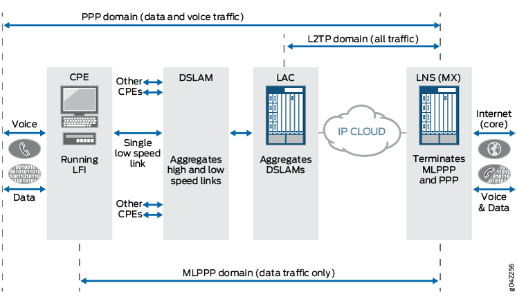
The following three domains are shown passing traffic through the LNS network:
PPP domain—Contains data and voice traffic
MLPPP domain—Contains data traffic only
L2TP domain—Contains all types of traffic
PPPoE Subscribers and MX Series
Figure 2 shows a network diagram with the MX Series terminating PPPoE sessions that include both the PPP and MLPPP bundles.
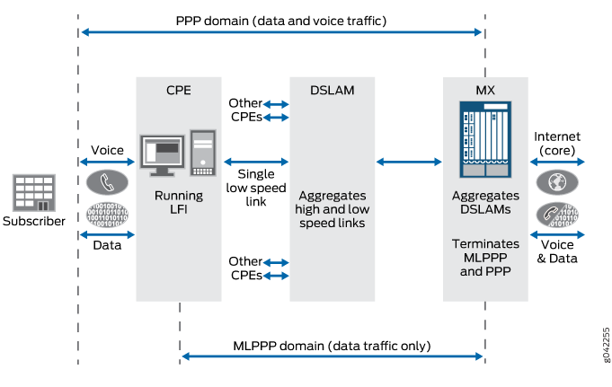
The following two domains are shown passing traffic through the network:
PPP domain—Contains data and voice traffic
MLPPP domain—Contains data traffic only
Change History Table
Feature support is determined by the platform and release you are using. Use Feature Explorer to determine if a feature is supported on your platform.