Validation Framework
Extensive testing of best practice architectures is key to the Juniper Validated Design program. JVDs qualify and quantify these best practice architectures, allowing you to know exactly what you're buying and to spend your time deploying and managing your network instead of designing it.
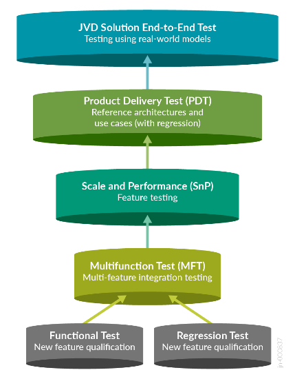
JVDs employ a layered testing approach to deliver reliability and repeatability. Individual features receive functional testing. Multifunction testing builds on this functional testing to see if multiple features work together. Product delivery testing builds upon multifunctional testing to validate that these features combined perform as expected for tested use cases, and JVD testing builds upon product delivery testing by testing multiple products together (including third-party integrations where appropriate) to ensure that all these products combined make an industry-leading solution.
Testing with real-world applications and traffic provides more accurate data regarding performance and response to different configurations. The standardized nature of JVDs ensures the same network architecture is deployed in multiple testing environments, and the use of JVDs by multiple customers allows for any lessons learned in production deployments to rapidly benefit all JVD customers. The more JVDs that are deployed worldwide, the greater the value they provide to all.
Test Bed
The test bed environment consists of a 3-stage EVPN/VXLAN fabric managed by Juniper Apstra, with four ESI server leaf switches configured as two redundant pairs, one single (non-redundant) server leaf (non-ESI), and two redundant border leaf switches connected to two spines. An external router is also connected to the border leaf switches. A traffic generator is connected to the test ports on the external router and the ESXi servers.
To ensure all the platforms specified in are validated, two data center topologies connected using DCI were used. Since there were multiple devices for each role, the devices were swapped, and the tests were repeated with each combination. For instance, border leaf switches were swapped with QFX5130-32CD, PTX10001-36MR, ACX7100-32CD, and so on.
.png)
VRF Characteristics:
RED VRF:
- VLANs 400–649 with IRB v4/v6
- on DC1-SNGL-LEAF1 single access port
- on DC1-ESI-LEAF1 single access port, AE1 and AE2
- on DC1-ESI1-LEAF2 single access port, AE1 and AE2
- on DC1-BRDR-LEAF1 to distribute routes to external-router
- on DC1-BRDR-LEAF2 to distribute routes to external-router
- VLANs 400–649 on each test port with 10 unique MAC/IP per VLAN
- DHCP client on TP3
- External DHCP server on TP17
Blue VRF:
- VLANs 3500–3749 with IRB v4/v6
- on DC1-SNGL-LEAF1 single access port
- on DC1-ESI-LEAF1 single access port, AE1 and AE2
- on DC1-ESI1-LEAF2 single access port, AE1 and AE2
- on DC1-BRDR-LEAF1 to distribute routes to external-router
- on DC1-BRDR-LEAF2 to distribute routes to external-router
- VLANs 3500–3749 on each test port with 10 unique MAC/IP per VLAN
- DHCP client on TP3, TP4, TP5
- External DHCP server on TP2
Platforms / Devices Under Test (DUT)
| Devices under Test (Validated Devices) | |||
|---|---|---|---|
| Solution | Server Leaf Switches | Border Leaf Switches | Spine |
| 3-stage EVPN/VXLAN (ERB) | QFX5120-48Y-8C | QFX5130-32CD | QFX5220-32CD |
| QFX5110-48S | QFX5700 | QFX5120-32C | |
| EX4400-24MP | ACX7100-48L | ||
| ACX7100-32C | |||
| PTX10001-36MR | |||
| QFX10002-36Q | |||
Test Bed Configuration
Contact your Juniper account representative to obtain the full archive of the test bed configuration used for this JVD.