Use Case and Reference Architecture
The architectures for EX Series Switches and other elements such as APs and WAN routers at a branch are rather simple by nature. Either you have:
Network designs covered in this JVD:
- One or more standalone switches connected to a WAN router. Access points are then connected to the switch (usually also using PoE). The WAN router is usually connected via a single non-redundant uplink to save costs.
- Two or more switches that form a Virtual Chassis connected to a WAN router. Access points are then connected to the Virtual Chassis (usually also using PoE). Here, we recommend using multiple links for the uplink by adding an IEEE 802.3ag link aggregation configuration for redundancy.
- For larger branches those Virtual Chassis then might be cascaded and then you have an access and a distribution Layer. This design may even be comprised having two link aggregation groups (LAGs) or bundles depending on the WAN router capabilities.
Network designs not covered in this JVD:
- A small campus fabric such as EVPN multihoming. This has a separate JVD found here.
- An AP directly connected to a WAN router.
Figure 1 shows the three main architectures that were tested end-to-end with EX Series Switches managed by Juniper Mist cloud as part of this JVD.
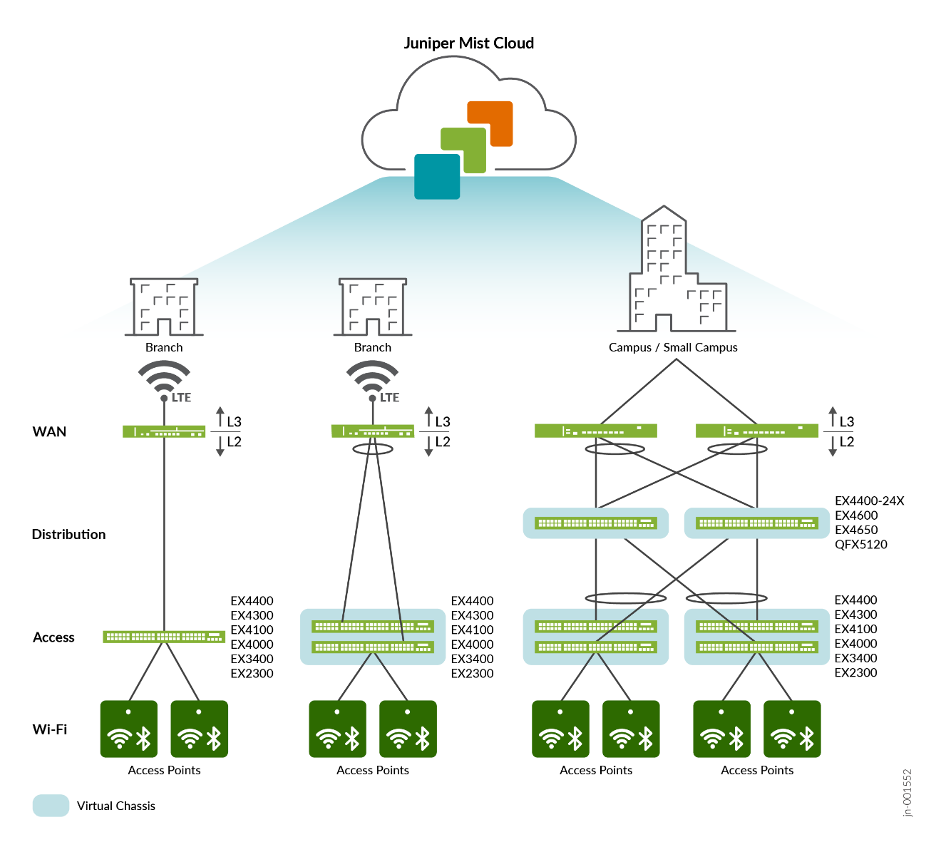
You may find references using a routing protocol such as OSPF between the distribution switch (as Virtual Chassis) and WAN router. Such designs are seldom used today because designs such as campus fabric EVPN multihoming are more popular in this case.
In addition to multiple standalone switches, Juniper Networks provides Virtual Chassis as a technology which combines multiple switches and manages them as one logical unit.
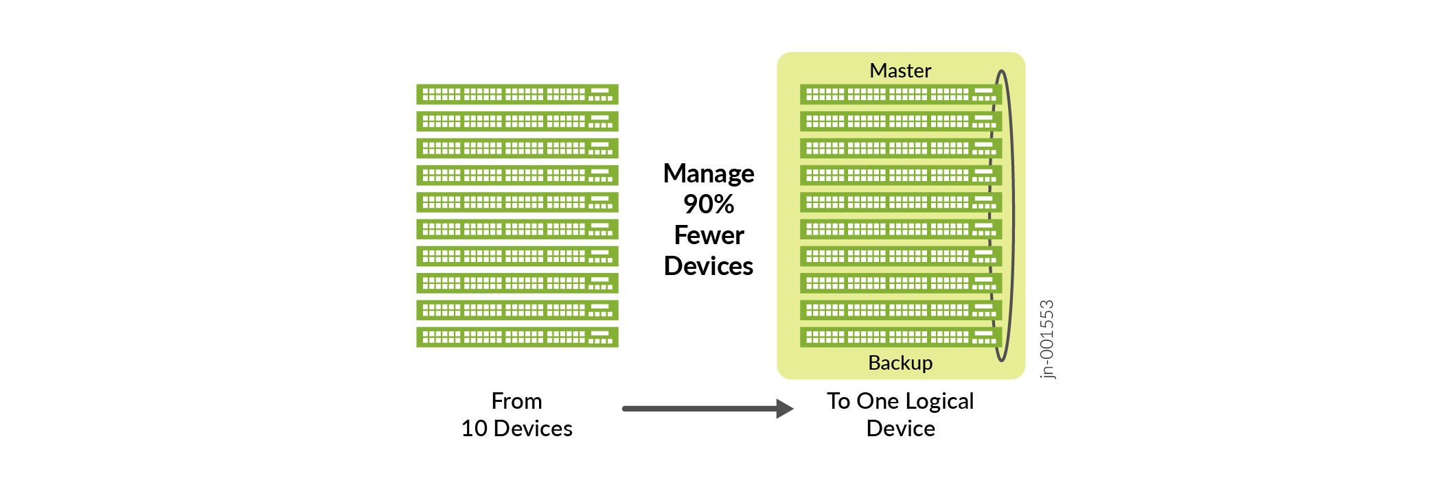
Implementing Virtual Chassis has the following major advantages:
- A Virtual Chassis is managed as a single switch.
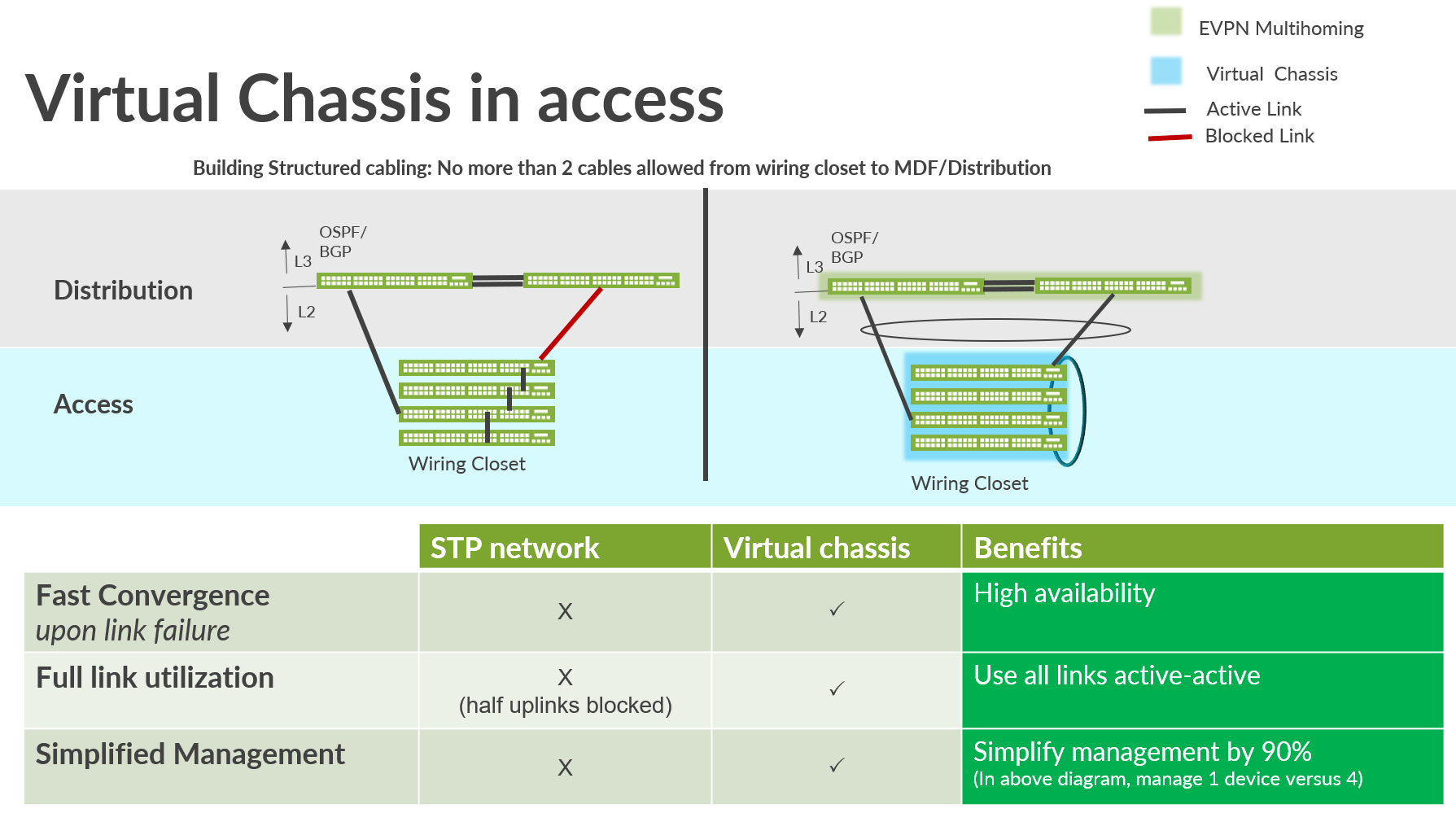
- The convergence time on link failure is faster than with the traditional spanning tree approach.
- All uplinks can be active at the same time using link aggregation. With spanning-tree protocols, only one link can be active at the same time.
Not a subject of this JVD but, should you consider using Virtual Chassis in a Juniper Mist cloud-managed campus fabric, the Virtual Chassis can only be deployed at the access layer.
Figure 3 highlights the general advantage of using Virtual Chassis versus a traditional spanning tree method.
Most EX Series Switches attempt to form a Virtual Chassis automatically from factory state when they are powered on. Hence, there is no manual intervention needed during installation. The connection toward the Juniper Mist cloud to manage the device may use a dedicated management port or use the preferred in-band management through any revenue port.
Table 1 shows which EX Series Switch models support which Virtual Chassis formation method:
| Switch Model Used in Virtual Chassis | VC Connections Made Through | VC Formation Support |
|---|---|---|
| EX3400, EX4100, EX4100-F, EX4300, EX4400 & EX4600 | Special Backplane connectors called VCP Ports | Automatic on boot (ZTP support) |
| EX4000, EX4100-H | Predefined Uplink-Ports on Front Pannel | Automatic on boot (ZTP support) |
| EX2300, EX4650 and QFX5120 | Uplink-Ports on Front Pannel | Pre-staging needed |
| EX4400-24X | Front Pannel-Ports (after they are converted to HGoE) | Pre-staging needed |
Uplinks to the WAN router should utilize an IEEE 802.3ad LAG with active LACP. The WAN router must support a feature such as “force-up” on at least one interface to build a LAG between the WAN router and the switch. The details are explained in the Best practices when using Link Aggregation on the uplink Interfaces section.