Solution Architecture
The 3-stage fabric topology created in JVD 3-Stage Data Center Design with Juniper Apstra will be used for the purposes of this JVDE. There are two spines, three server leaf switches, and two border leaf switches. For brevity of this document, the whole process of setting up the data center blueprint is not covered in this document. Figure 1 shows the data center blueprint from Juniper Apstra.
3-Stage Blueprint Topology
In the below topology, Figure 1, racks are shown for border leaf switches, ESI leaf switches, and single leaf (non-ESI) switches. The leaf switches are connected to generic servers, including ESXi servers. When NSX-T is configured on the ESXi servers (as discussed in walkthrough sections), the virtual machines running on these servers can be micro-segmented based on security needs. This helps to improve security by reducing the attack surface and limiting the lateral movement of threats within your environment.
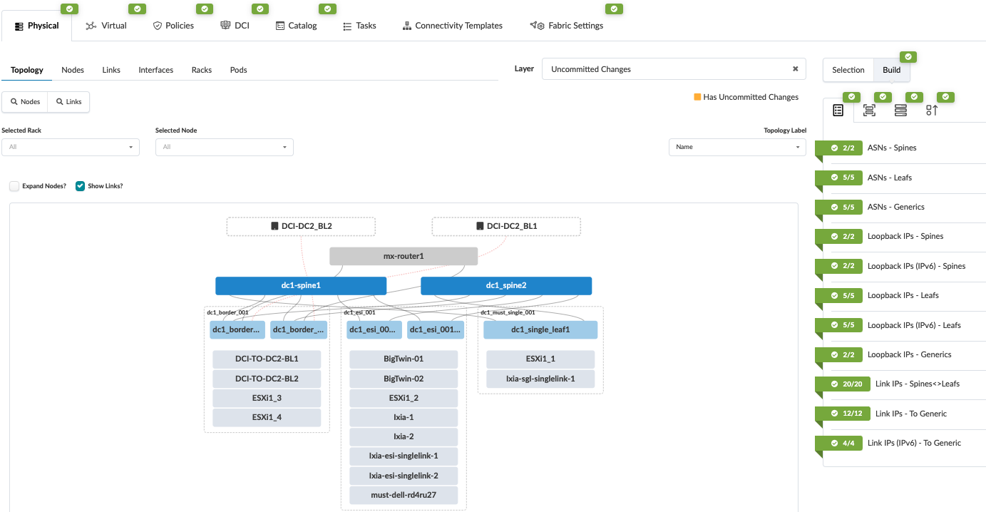
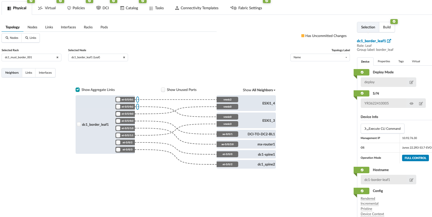
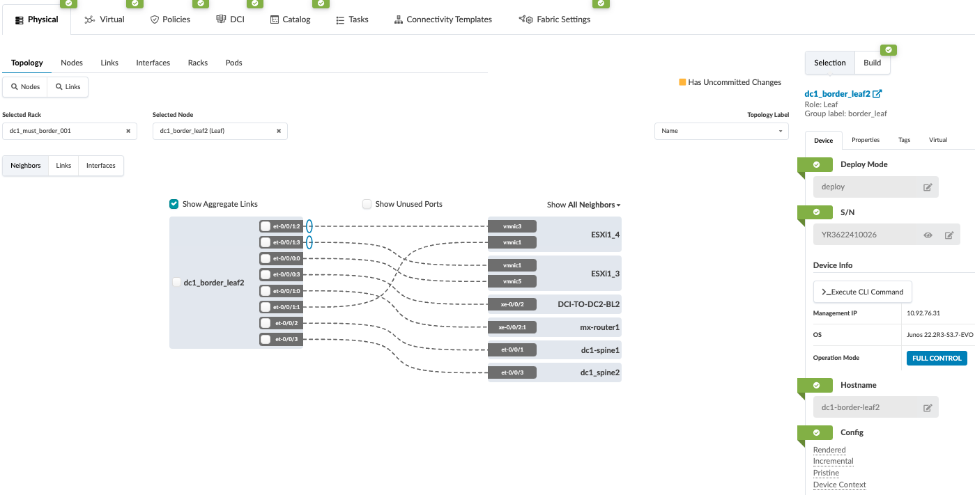
From the 3-stage topology above the border leaf switches are the gateways to the NSX-T edge routers. The ESXi servers connected to the border leaf rack host the NSX-T Edge routers as virtual machines. The following graphic shows the detailed border leaf connectivity towards the ESXi servers.
VMware NSX-T Edge Cluster
From VMware’s documentation: An NSX Edge Node is a transport node that runs the local control plane daemons and forwarding engines implementing the NSX-T data plane. It runs an instance of the NSX-T virtual switch called the NSX Virtual Distributed Switch, or N-VDS.
For the purpose of this document, a single NSX-T Edge cluster is deployed with one edge node. An edge node is a virtual machine created on the ESXi server in vSphere. We highly recommend deploying more than one edge node on separate ESXi hosts.
In production data center implementation to guarantee service high availability, we recommend that multiple NSX-T Edge Nodes or Edge Node clusters are deployed. This can be a single cluster with a maximum of 10 Edge Nodes, depending on the number of ECMP paths available. For more information, refer to the VMware NSXT Reference Design guide. Edge Nodes are ‘service appliances’ that provide pools of capacity. Edge Nodes provide network services that are not distributed down to the hypervisors and cannot be used for any other purposes. They provide the physical network uplinks (pNICs) that connect to data center fabric (underlay). In NSX-T 3.0 and later, the types of Edge Nodes supported are bare metal edge and VM edge. Edge Clusters are a group of Edge Transport nodes that provide a scalable, high-throughput, and highly available (redundant) gateway for logical networks created in NSX-T. This helps to guarantee the service availability of tier-0 and tier-1 gateways. For more information on high availability failover, refer to the VMware NSXT Reference Design guide.
In an ERB architecture, such as the one used in the underlying JVD used by this JVDE, border leaf switches serve as the gateway to external networks. Pursuant to this design philosophy, in this JVDE, the VMware NSX-T edge node terminates on the border leaf switches.
Figure 4 shows how the Edge Node terminates on the border leaf switches. The setup of the NSX-T Edge VDS port connectivity is discussed later in this document.
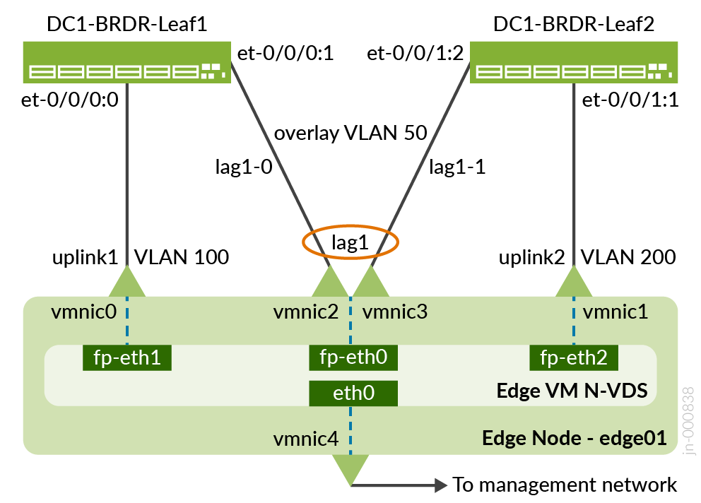
Transport Node Networking
From VMware’s documentation: Transport nodes are hypervisor hosts and NSX Edges that will participate in an NSX-T data center overlay. For a hypervisor host, this means that it hosts VMs that will communicate over NSX-T data center logical switches. For NSX-T Edge nodes, this means that it will have logical router uplinks and downlinks. All ESXi hosts in this document will be added to the NSX-T transport zone.