Juniper Mist WAN Assurance Configuration Hierarchy
Introduction to Configuration Hierarchy
Juniper Mist WAN Assurance Configuration
For network administrators, it’s essential to understand that each piece of the puzzle builds your network's policies, security, and connectivity in Juniper Mist WAN Assurance cloud service. A full SD-WAN deployment requires each part to complete intersite connectivity. Mist automatically translates your traffic intent to configurations for WAN Edge devices using Mist’s intent-based networking (IBN) model. Each part works together to build complex interface assignments, security, routing policies, and—depending on the platform—destination zones. Therefore, understanding the Mist intent model is crucial as we dive into the configuration hierarchy for Juniper Mist WAN Assurance.
Intent-Based Routing
IBN solves several problems. For example, consider the need for secure communication between two networks. An intent model states that secure communication requires a secure tunnel between Network A and Network B. In this scenario, a network administrator identifies which traffic uses the tunnel and describes other desired general properties. But an operator wouldn’t specify or even know how to build a tunnel. To implement a tunnel, you must know how many devices to secure, how to make BGP advertisements, and which features and parameters to turn on. By contrast, an IBN system automatically generates an entire configuration of all devices based on the service description. It then provides ongoing assurance checks between the intended and operational state of the network, using closed-loop validation to continuously verify the configuration’s correctness. IBN is a declarative network operation model. It contrasts with traditional imperative networking, which requires network engineers to specify the sequence of actions needed on individual network elements and creates significant potential for error.
Intent-based model key characteristics:
- Do not require as much explicit direction as traditional network models require.
- Build policies based on which network goes to which application.
- Configure Juniper Mist WAN Assurance Networks and Applications organization-wide.
- Push relevant configurations only.
- Configure only the Applications that a device uses. If a device doesn’t use an Application, the intent-based network doesn’t configure it on that device.
Let’s look at the example of configuring DHCP on a LAN and assume that the interface is already configured and assigned to a zone.
Required steps in the Junos CLI:
- Navigate to the Junos system services level and enable the DHCP-local-server for your interface.
- Navigate to the Junos system address assignment and create an address pool specifying the target network, the range of addresses for the pool, the default gateway, and any other DHCP attributes.
- Navigate to your security zone and enable host-inbound traffic for the DHCP system service to allow the SRX Series to process DHCP requests from clients.
The above steps require multiple configuration lines spread across three configuration hierarchies at a minimum.
The same workflow is significantly streamlined in Mist:
- First, navigate to your LAN configuration and open it for editing.
- Next, enable the DHCP Server radio button to unlock the configuration and populate the required fields (IP Start, IP End, and gateway).
- Save the LAN configuration and then save the device configuration.
Configuration Hierarchy Elements
- Organization-Wide Configuration Elements
- Networks
- Route Advertisement (Advertise via Overlay)
- Access to Mist Cloud
- Users
- Applications
- Traffic Steering
- Application Policy
Organization-Wide Configuration Elements
The top of the Mist configuration is called your Mist organization. These elements impact your entire software-defined wide area network (SD-WAN) deployment. The different components at this configuration level become building blocks for sources and destinations across your deployment. Once identified, traffic requests associate a sender and the desired destination appropriately. The elements help build different Juniper Mist WAN Assurance deployment components depending on your platform. Identifying the source and destination will build IPsec tunnels across the WAN and associated security zones on the Juniper® SRX Series Firewall. These components on the Juniper® Networks Session Smart™ Router become the corresponding source and destination to help build the Secure Vector Routing (SVR) metadata exchange. The two platforms approach the challenge of SD-WAN uniquely, which makes it important to know your Juniper Mist WAN Assurance platform.
Networks
The Juniper Mist WAN Assurance Network is the “who” in the Mist intent-driven paradigm. Networks are sources of the request in your network. Networks enable you to define groups of “Users.” Once you create this element in your Mist design, the network is defined for use across the entire organization.
Characteristics of Networks on the Juniper® Networks Session Smart™ Router:
- Mist Networks create Tenants in the background for SVR.
- The Session Smart Router identifies Tenants at the logical interface (Network Interface).
- LAN and WAN interface configurations identify your Tenant (request source).
Characteristics of Networks on the Juniper® SRX Series Firewall:
- Networks create Address books used as the source for Security Policies and Advanced Policy Based Routing (APBR) Policies.
- Configurations are applied to the device if an Application Policy is configured.
- For the LAN, the zone's name is derived from the name of the specified network.
- For the WAN, the zone’s name is based on the name of the WAN.
Route Advertisement (Advertise via Overlay)
WAN Assurance is about the abstraction of the transport network into the SD-WAN. You can advertise networks through SD-WAN for control and reachability with route advertisement. Then established networks in your LAN segments can be advertised across the overlay. Setting up these networks generates the source addresses for service policies. Network Address Translation (NAT) for the source and destination can route traffic to your users if needed.
The purpose of SD-WAN is intersite connectivity. Therefore, networks can be advertised through overlay to enable reachability between your SD-WAN devices. With this setting, your network will share the address across the WAN so other devices know how to reach it. You can advertise to other spokes or to hub LAN neighbors. For more information about this feature, see Network Settings.
Access to Mist Cloud
Mist is a full-stack solution. Only some of your devices are WAN Edge or SD-WAN routers. Specific devices will want access to the Mist Cloud to leverage other solutions like Wireless and Wired Assurance on Wireless APs and switches. Access to Mist Cloud will automatically generate specific firewall/policy rules enabling the devices to phone home to Mist without needing an explicit application policy. However, you don’t want this level of access on all devices behind the WAN Edge in an SD-WAN deployment because doing so can pose a policy challenge for routers. Generally, select Access to Mist Cloud for APs or switches, so that you can monitor and troubleshoot these devices from the Mist portal.
Enabling access to the Mist cloud ensures that anything sitting behind the WAN Edge can reach the Mist cloud without needing to express policies for connectivity manually. Ports and protocols for this setting include the following:
- TCP/443
- DNS/53
- SSH/2200
- NTP/123
- Syslog/6514
- ICMP
Users
Don’t let the label fool you. Users does not represent a single user on your network. Users are subsets of subnets or indirectly connected subnets. Since Networks are "who,” think of Users as a subdivision of that network identity. There are often universal rules to treat networks the same. For example, for 99% of your traffic, you want sessions to do the same thing. But what about when you’re blocking access to a corporate network from a guest network, and only one IP needs printer access? In this situation, add a User. For those familiar with the Session Smart Routing platform, compare a User to a Tenant. You also might create Users to define indirect prefixes on the network.
- Users can define granular permissions. For example, your LAN segment may need Internet access, but you must restrict it to a particular network device. So here, you’d create an access policy around that desktop.
- You sometimes need to reach indirectly connected prefixes behind a router on the LAN segment. For example, picture a router behind a device that connects multiple devices to an outside application. In this case, you can add users to a network that you've specifically configured as a "network not directly attached." For more information, see Network Settings.
Applications
Applications comprise the “what” in the Mist intent-driven model paradigm. Applications are what your network delivers. Applications represent traffic destinations and are named for what a client would access, like a “database” or the “Internet.” Once you create this element in your Mist design, the Application is defined for use across the entire organization.
Characteristics of Applications on the Juniper® Networks Session Smart™ Router
- Mist applications create services in the background for SVR.
- Applications can be ports, protocols, prefixes, custom domains, or app names from the built-in AppID library.
Ports, protocols, and prefixes are where all the policy revolves.
- Custom Apps are a set of ports, protocols, or prefixes.
- Apps map to the Internet app-id.
- URL Categories are force-point URLs.
Characteristics of Applications on the Juniper® SRX Series Firewall
- Applications determine the destination used in a security policy.
- A prefix of 0.0.0.0/0 with protocol “any”, is resolved to any within the Juniper Mist WAN Assurance policy. No address book or application is necessary.
- Custom Apps on the WAN Edge use the SRX Series on-box engine “type” and are a combination of an address book and applications.
- Apps map to the SRX Series Layer 7 AppID engine.
- URL Categories are force-point URLs.
Traffic Steering
Traffic Steering is the “how” in the Mist intent-driven model paradigm. Traffic Steering is how you define the different paths that traffic can take to reach its destination. If traffic to an application has multiple paths, you can restrict the paths to a subset of paths and configure an order of preference. You can also load and balance numerous streams across the available paths.
Characteristics of Traffic Steering on the Juniper® Networks Session Smart™ Router:
-
The Juniper® Session Smart Router™ is session-based and uses continuous path monitoring techniques for both underlay and overlay paths to find the best available path for any application.
- There are three steering strategies for the SSR Series:
-
Ordered: This is the default—go in order of the list. Active paths at the top take priority. If a path goes down, then move to the next active path in the list. This creates an ordered list.
-
Weighted: Allows you to set your desired order based on weight. For example, two weighted paths, both set to 5, result in ECMP sessions across the two paths. On the other hand, two weighted paths, with one set to 5 and the other set to 10, result in ordered steering, with sessions taking the lower-weight path first.
-
ECMP: Fully load balance traffic with an equal-cost multipath algorithm. Sessions will be split evenly across all available paths.
-
-
Unlike the SRX Series Firewalls, traffic Steering is not required on an application policy for the SSR if there is already a route for the traffic in its RIB. There are situations where configuring traffic steering on an application policy will result in undesirable behavior. See Internet Backhaul Through an SSR Hub for more information.
-
The SSR supports traffic steering policies that can steer traffic in two ways:
-
Towards the overlay with various options for steering this traffic over different WAN paths using Secure Vector Routing (SVR). For traffic steering in the overlay, Mist WAN Assurance relies on BGP to route traffic between SSR devices. You can leverage this behavior to exchange and propagate routes between your existing network(s) and your SSR device(s).
-
Locally routed out one or more specific interfaces, which is common for local breakout (underlay) traffic. For customers who do not want to perform dynamic routing with the SSR, or customers without existing dynamic routing solutions, see Internet Backhaul Through an SSR Hub for details.
-
-
For application policies that have a block action, do not enter any traffic steering
-
SSR employs a deny-by-default behavior. You do not need to create blocking policies unless a particular network object already has access to a broader application and you wish to limit a specific range within that address space.
Characteristics of Traffic Steering on the Juniper® SRX Series Firewall:
- The Juniper® SRX Series Firewall is zone-based, and the destination zone is determined by the paths configured within a Traffic Steering policy.
- Traffic Steering configures forwarding-type routing instances and the relevant routing policy to import routes. For your SRX Series, this routing instance is used in APBR.
- There are several steering strategies for the SRX Series:
- Ordered: Default, go in order of the list. The top takes priority, then failover to the next. Creates an ordered list.
- Weighted: Allows you to set your desired order based on weight. For example, two weighted paths, both set to 5 results in ECMP across the two paths. On the other hand, two weighted paths with one set to 5 and the other set to 10 results in ordered steering with traffic taking lower weight path first.
- ECMP: Fully load balance traffic with an equal-cost multipath algorithm. Traffic will be split evenly across all available paths.
Application Policy
The “who,” “what,” and “how” come together with Application Policy. The Mist intent-driven model simplifies manually generating routes and security policies through Junos OS on the SRX Series with thousands of lines of code. It also simplifies deploying a Session Smart Router for those transitioning from a Conductor-based Session Smart deployment to WAN Assurance. You no longer need explicit permissions and interface assignments to get up and running. WAN Assurance is zero trust. This feature is both implied and part of the intent-driven model. You must explicitly grant permission to allow a Network to access to an Application. Otherwise, it will not route.
Order only matters when egressing your local network on the Juniper® Networks Session Smart™ Router. The Session Smart Router uses the most specific matches. As a result, traffic steering isn’t necessary for local traffic. Also, using a block in your Traffic Steering does not work with SVR, as it undermines the proprietary process. If you don't want a device, subnet, or network to access an Application, don't create traffic steering for that device.
Characteristics of Application Policy on the Juniper® SRX Series Firewall:
The steering path determines the destination zone in the SRX series. Please ensure that policies have Traffic Steering assigned because the order of policies matters when working with the SRX Series. As a traditional zone-based firewall, it uses a list of rules that generate filters and policies. Most specific rules should be at the top of the Application Policy list on the SRX Series.
Scaling Your Network: Automation in Mist
- WAN Edge Templates
- Hub Profiles
- Site Variables
- Introduction to Applying Templates
- Import and Export Templates
- Overriding the Template
- Organizational-Level Application Policy
WAN Edge Templates
Once basic configuration elements of SD-WAN are in place, Mist enables you to deploy new WAN Edge devices through WAN Edge templates. All that previous configuration can be templated with WAN Edge templates. These templates work for a standalone Edge device to a full SD-WAN deployment with hundreds of sites. The automation process removes errors and simplifies deploying multiple spoke sites and headends.
Templates reduce or eliminate common configuration tasks and remove human error when configuring multiple devices. WAN Edge templates:
- Enforce standards across a deployment.
- Ensure that all your network devices point to the same DNS (8.8.8.8).
- Provide predictable behavior because they use the same Network Time Protocol (NTP) for synchronization and logging. (This also affects specific certificates.)
- Simplify troubleshooting and management. Figure 1: WAN Edge Template

However, WAN Edge templates do more than automate tasks. You might use a template to standardize a configuration that can be applied consistently across sites even if you don't actually deploy all features at all sites. For example, you might not need a guest network at every site, but by including the configuration in the template, you're reserving that interface. If future plans call for a guest network, the interface is ready to be used.
These templates also allow for:
- Bulk orders of hardware for ports and site groups through specific models.
- Specific use cases and traffic flows.
- Different corporate LAN networks.
- Guest networks.
WAN Edge templates automatically configure repetitive information like an IP, gateway, or VLAN. In addition, WAN Edge templates can include traffic steering, access policies, routing preferences, and any additional configuration you'd like to standardize. Remember that you'll need a prefix, NAT, or other local information for WAN and LAN connectivity.
Hub Profiles
Hub profiles work with WAN Edge templates. Hubs are not at the Edge and are universally unique throughout your network. Hubs affect how Mist builds the overlay network. Each branch and remote office build the SD-WAN communication to the hub. Topology is determined by overlay endpoints that make up a single overlay. Every hub WAN interface creates an overlay endpoint for spokes. Spoke WAN interfaces map the appropriate hub WAN interfaces, defining the topology. This is the abstraction of the transport network. Because the two platforms for WAN Assurance solve the abstraction differently, you need to understand their nuances when building that overlay network.
Juniper® SRX Series Firewall
The SRX Series overlay SD-WAN combines a virtual router for route separation and IPsec tunnels for secure transit traffic. WAN configurations determine the topology and build the overlay network. One thing to note is that you can implement only one overlay per organization. However, you can have many paths within this overlay across multiple types of transport and securely isolate and forward traffic. For SRX Series devices, the overlay combines a security zone, virtual router, and IPsec tunnels.
Juniper® Networks Session Smart™ Router
The Session Smart overlay SD-WAN is your neighborhood, which involves proprietary communication through BFD on port 1280 for liveness and jitter, latency, and loss between Session Smart peers. When you configure a WAN interface on a hub profile, it creates an overlay hub endpoint. On the Session Smart Router, the endpoint is the receiving end of the SVR.
A few things happen when you map a spoke WAN Interface to the overlay hub endpoint. The spoke will establish peer connectivity and identify the neighborhoods and vectors for SVR, which is the Session Smart abstraction of the transport network.
A final note on the overlay: The SRX Series and Session Smart Routers cannot exist in a single overlay. These devices can be paired through BGP at the hub, but their solutions to create intersite connectivity are unique and cannot operate together in the same overlay. If you have migration plans, identify which routes need advertisement and advertise at the hub.
Keep the following hub profile considerations in mind:
- Hub profiles must be built first, so spoke templates know where to connect.
- Hubs must have static IPs for overlay endpoints.
- The overlay endpoint configuration is exposed in the WAN Edge spoke template.
- There is no limit to the number of hubs you can incorporate within these
guidelines:
- One hub per datacenter
- Two hubs for redundancy (HA clusters)
Spokes choose the primary hub through traffic steering and an Application Policy. Zero-touch-provisioning (ZTP) requires DHCP (for physical implementation) unless ZTP is done and then migrated to the destination network. You can pre-stage the devices manually, too.

Site Variables
Site variables are configured on a per-site basis. When planning a network holistically, you can create standard templates for specific WAN Edges and WAN Edge clusters. Ideally, you have only one WAN Edge device per site (or a single logical WAN Edge if the device is clustered). Since variables can differ per site, administrators use them in templates or the WAN Edge configuration page. The transformation happens when the configuration is rendered and pushed to the device.
Keep the following site variable considerations in mind:
- The syntax for variables matches Jinja2 and is contained within double curly brackets, like this: {{variableName}}
- The UI enforces the leading and trailing curly brackets as part of the name.
- Site variable limitations:
- No spaces in the variable.
- No special characters (except underscore) within the variable field.
- Variables can be used only in one field and cannot specify an entire prefix.
For example, 10.88.88.88/24 would need at least two variables, one for the IP address (10.88.88.88) and another for the prefix length (24).
Figure 3: Site Variables
The best way to use the real power of templates is with site variables. Many configuration items are required to deploy the hardware. It makes sense to combine the WAN Edge templates and site variables. Consider the following situation where you can define entire IP subnets of the first three octets, leaving minimal configuration at each device:
Create standard templates and place variables in standard interfaces like your WAN in either of these ways:
- With a WAN1PFX variable, let’s say {{192.168.170}}, and in the WAN field on the Configuration page, it would be {{WAN1PFX}}.1 for the local IP and {{WAN1PFX}}.2 for the gateway.
- You could define a {{WAN1IP}} and {{WAN1_GW}} pair of variables; however, there
are places where the subnet may be reused but not the specific IP.Figure 4: Site Variables in WAN Configuration

Another robust use case is the magic octet, where the third octet becomes a variable, and that variable might also apply to multiple fields. For example, a {{SITEID}} variable might be used for both the third octet and a VLAN tag. In that case, the network prefix might be 192.168.{{SITEID}}.1/24 with the {{SITE_ID}} VLAN ID. Remember that although WAN Edge templates apply only to the WAN Edge, site variables also apply to switches and APs. The purpose of the automation is to simplify deployments and increase reusability.
Introduction to Applying Templates
Remember that a site is a collection of all your assets in a single location. It is implied that there will only be a single WAN Edge. A key feature of Mist management through the Juniper Mist AI is your ability to use configuration templates to group WAN Edges and make bulk updates. Templates provide uniformity and convenience, while the hierarchy provides scale and granularity.
Import and Export Templates
No solution covers all circumstances. You can have multiple templates. To save time, clone a template. Then customize the cloned copy by modify it as needed.

Modifying Template Sample
{
"type": "standalone",
"ip_configs": {
  "LAN": {
    "type": "static"
    "ip":
"{{LAN1_PFX}}.1" ,
      "netmask": "/24*
     }
  },
  "dhcpd_config" : {},
  "dns_servers" : [
    "8.8.8.8"
   ],
....
}
Overriding the Template
Templates apply to sites, which apply to devices. Templates are used to standardize configurations, but exceptions always exist. Rather than create a slightly different template for one site, you override the template configuration on the device.

If you need to override the template, you can enable the Override Template Settings option for the required configuration blocks on a per-device basis. Figure 7 shows how you can override the DNS and the Application Policy but none of the other settings, such as WANs, LANs, or NTP servers.

The screenshot illustrates an all-or-nothing action. When you override the template settings, this configuration longer inherits any application policies from the WAN Edge template.
You need to have one of the following role assigned to you in order to override the configuration:
- Super User
- Network Admin (All Sites Access)
- Network Admin (Site Group or Specific Sites Access)
Organizational-Level Application Policy
Figure 8 shows Application Policy configuration option at the organization level.
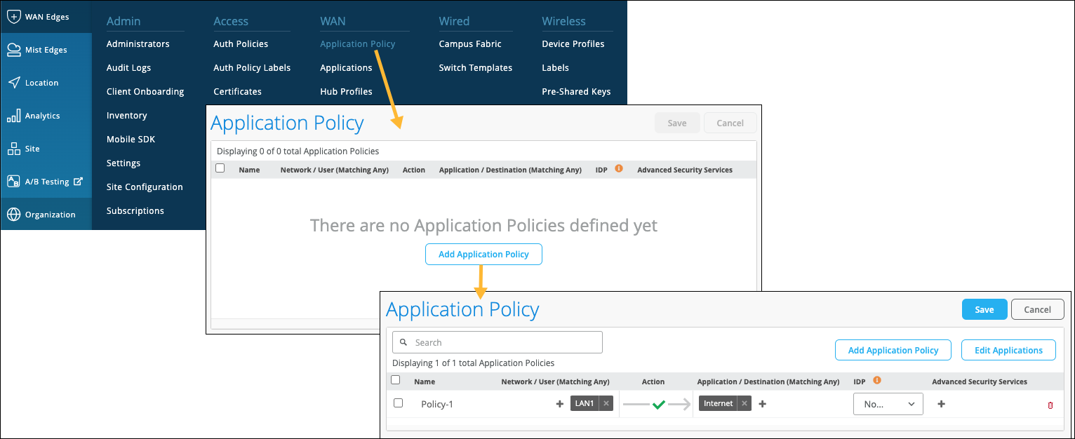
Although templates save time on deploying multiple devices, you might have various templates to account for different device models or slightly different configurations. You can create the same Application Policy on each template, but consider using an organization-level Application Policy as a shortcut. With an organizational-level Application Policy, you can create importable application rules into WAN Edge templates and hub profiles for large-scale network topologies.
Let’s explore some best practices and restrictions for using an organizational-level Application Policy. Give each organization-level Application Policy a globally unique name, or you'll get errors when saving the configuration. The imported policy has all the fields dimmed because it is not meant to be modified. There’s no organizational-level traffic steering, which makes sense, because traffic steering applies to local connections and intent.
Consider applying an organizational-level Application Policy to a LAN block or one subnet. If you create a LAN “supernet” of a 10/8, the policy will allow anything sourced from 10/any to reach the Internet, meaning it would work for all your sites. This is why planning is crucial. Design your network to streamline troubleshooting with similar traffic patterns regardless of deployment. For example, some sites have LTE, and traffic must egress there on that site instead of others. In addition, some sites are standalone, and others are SD-WAN. A universal policy could apply to both by telling traffic steering on standalone sites to go out the WAN to the underlay, whereas the sites are going to the overlay for the SD-WAN spokes.
In summary, the use case for an organization-level policy is to describe network-wide traffic patterns regardless of the site; as a policy, you define what is and is not allowed. Then, when applied to the site or template (which applies to places), you add the steering portion giving you the final piece of the puzzle.
WAN Design Considerations
Figure 9 shows the workflow for WAN Edge provisioning.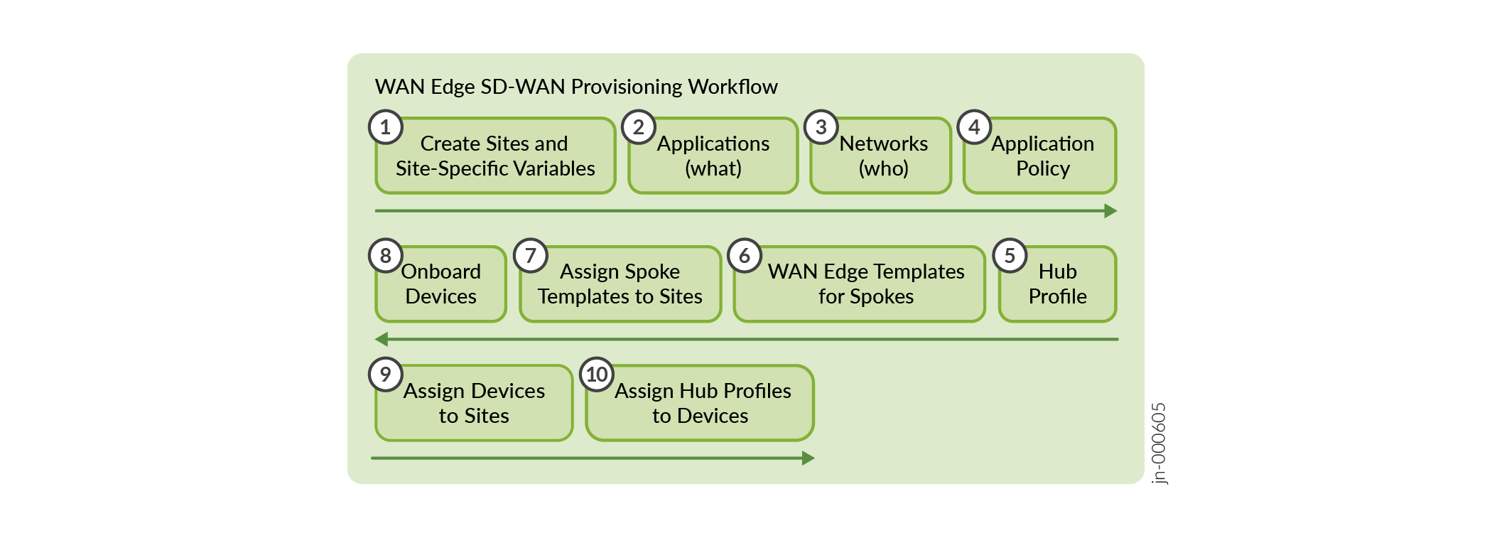
Reviewing the blocks that make up the completed project is essential to deploy an SD-WAN, as follows:
- Think about “who” (Network) makes up the source of requests in your organization.
- Consider “what” destinations (Applications) users access.
- Where do those elements go in your organization? Consider site types.
- Finally, consider “how” (Traffic Steering) those users get and gain access to their traffic destinations.
- Now you can use the power of Mist AI, templates, and variables for scale.
SD-WAN Provisioning
The order of operations matters. When preparing to implement SD-WAN provisioning, complete tasks in this order:
- First, plan your network with templates, thinking about the deployment holistically.
- Hub profiles must come before WAN Edge spoke templates.
- Design with your Applications (destinations of traffic) first, and then Networks (who).
You can analyze apps and become more granular later.
- Make sure you know your networks (sources of traffic).
Networks inform policy and traffic steering.
- Apply the appropriate Application Policy to both ends (spokes and hubs).
Strive for end-to-end reachability when establishing overlay endpoints. Keep in mind that you can’t connect an isolated MPLS endpoint to an Internet endpoint.