EVPN LAGs in EVPN-VXLAN Reference Architectures
This section provides an overview of the Juniper EVPN-VXLAN reference architectures and the role of EVPN LAGs in these architectures. It is intended as a resource to help readers understand EVPN LAG capabilities in different contexts.
The standard EVPN-VXLAN architecture consists of a 3-stage spine-leaf architecture. The physical underlay is IP forwarding enabled—all leaf to spine underlay links are typically IPv4 routed—and the logical overlay layer uses MP-BGP with EVPN signaling for control plane-based MAC-IP address learning and to establish VXLAN tunnels between switches.
Juniper Networks has four primary data center architectures:
Centrally Routed Bridging (CRB)—inter-VNI routing occurs on the spine switches.
Edge Routed Bridging (ERB)—inter-VNI routing occurs on the leaf switches.
Bridged Overlay—inter-VLAN and inter-VNI routing occurs outside of the EVPN-VXLAN fabric. Example: Routing occurs at the firewall cluster connected to the EVPN-VXLAN.
Centrally-Routed Bridging Mutual (CRB-M)—architecture where the spine switches are also connecting the existing data center infrastructure with the EVPN LAG. CRB-M architectures are often used during data center migrations.
EVPN LAGs in Centrally Routed Bridging Architectures
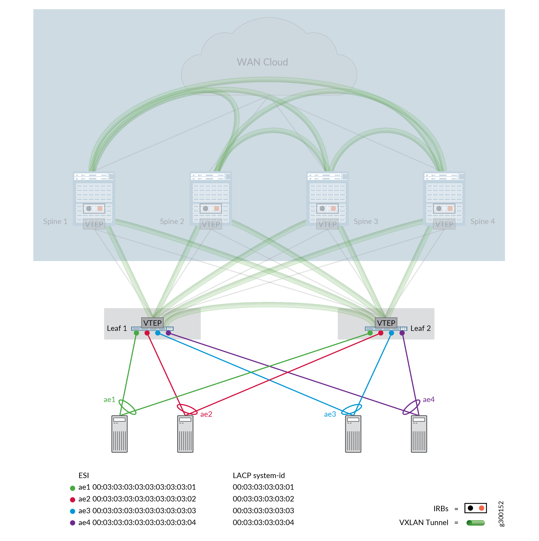
In the CRB architecture, we recommend provisioning the EVPN LAGs at the leaf layer and connecting two or more leaf devices to each server or BladeCenter.
Figure 1 illustrates EVPN LAG provisioning in a CRB architecture.

The same ESI value and LACP system ID should be used when connecting multiple leaf devices to the same server. Unique ESI values and LACP system IDs should be used per EVPN LAG.
EVPN LAGs in Edge Routed Bridging Architectures
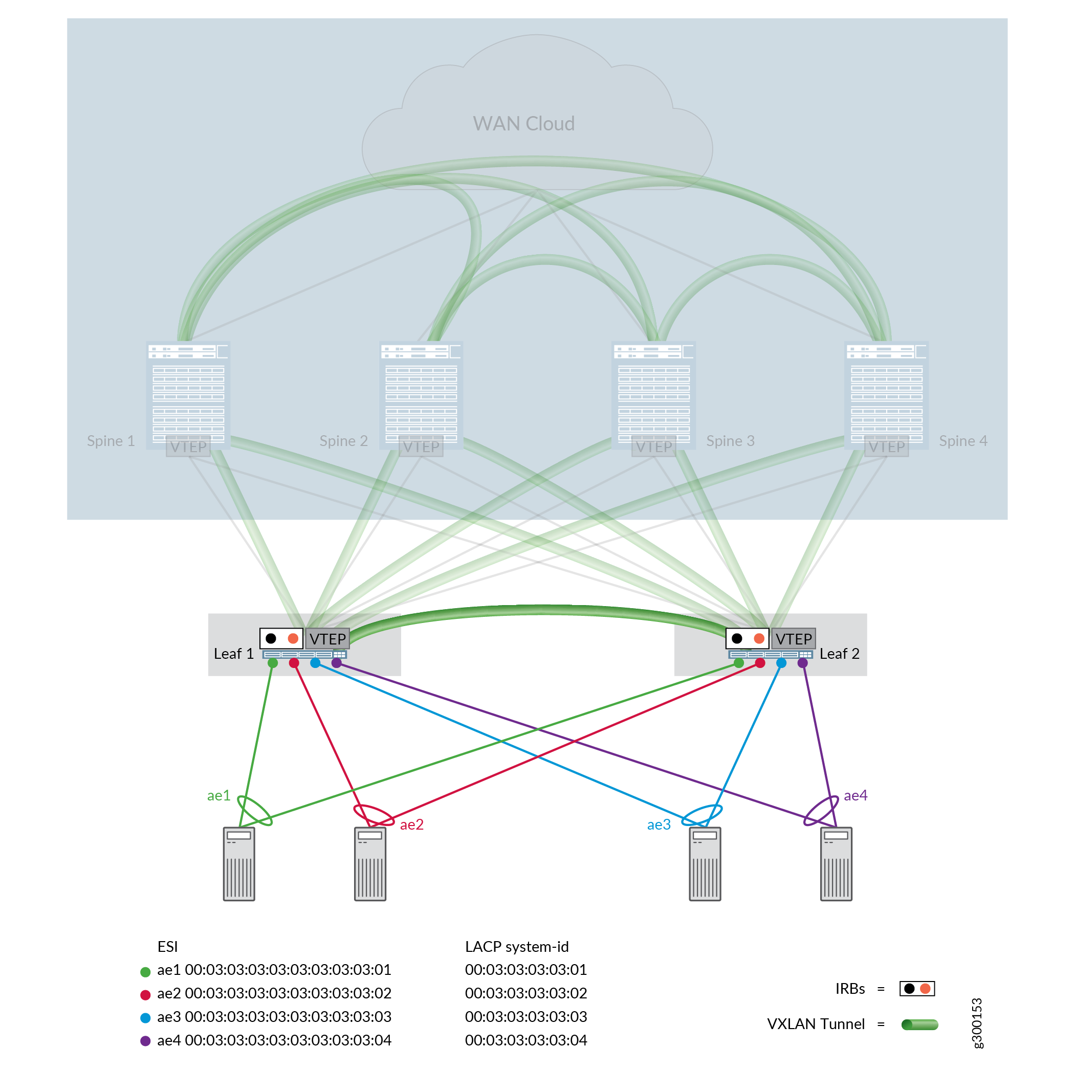
Figure 2 illustrates the use of EVPN LAGs within an Edge Routed Bridging (ERB) architecture. The recommended EVPN LAG provisioning in an ERB architecture is similar to the CRB architecture. The major difference between the architectures is that the IP first hop gateway capability is moved to the leaf level using IRB interfaces with anycast addressing.
The ERB architecture offers ARP suppression capability complemented by the advertisement of the most specific host /32 Type-5 EVPN routes from leaf devices toward the spine devices. This technology combination efficiently reduces data center traffic flooding and creates a topology that is often utilized to support Virtual Machine Traffic Optimization (VMTO) capabilities.

EVPN LAGs in Bridged Overlay Architectures
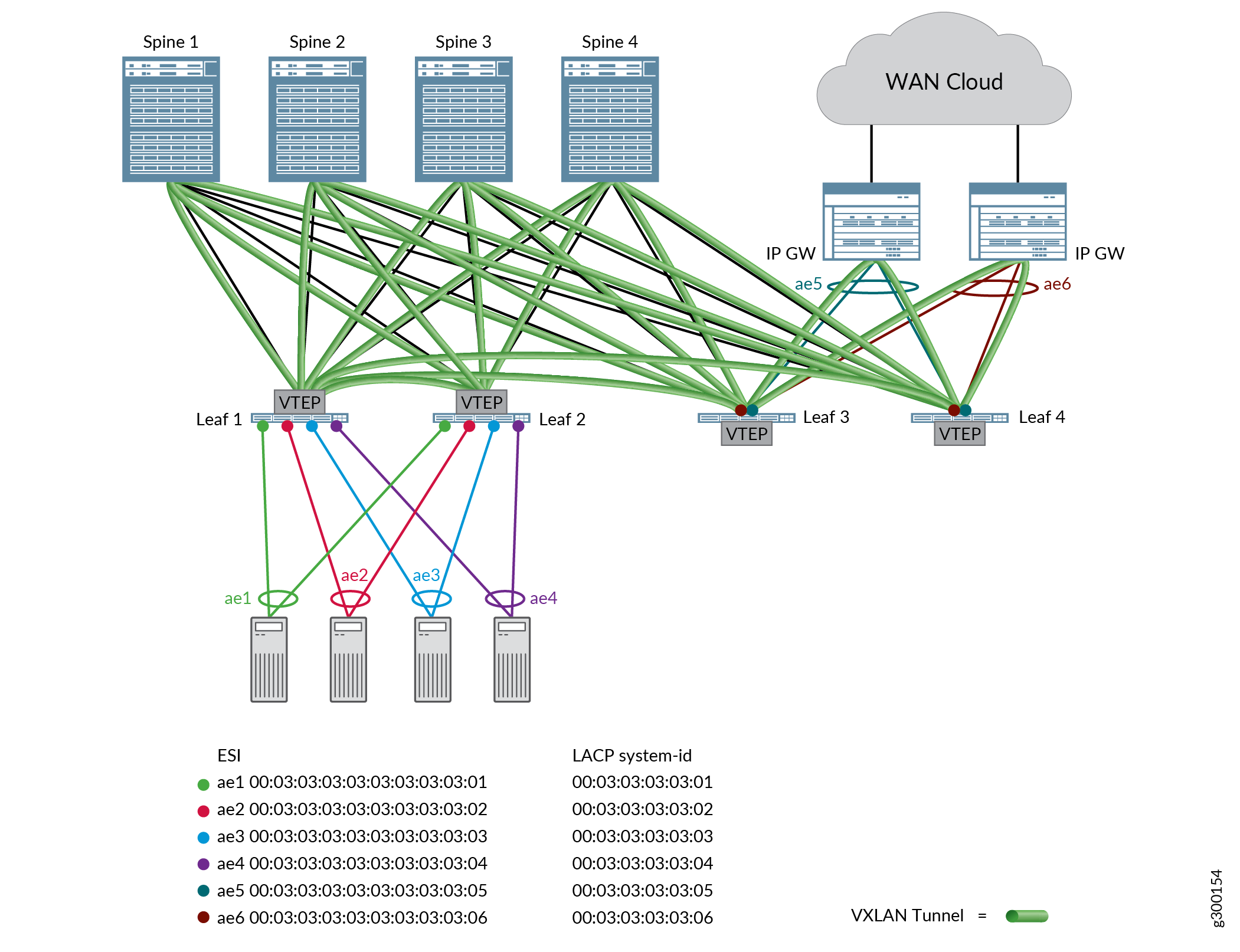
In a bridged overlay architecture, VLANs are extended between leaf devices across VXLAN tunnels. EVPN LAGs are used in a bridged overlay to provide multihoming for servers and to connect to first hop gateways outside of the EVPN-VXLAN fabric, which are typically SRX Series Services Gateways or MX Series routers. The bridged overlay architecture helps conserve bandwidth on the gateway devices and increases the bandwidth and resiliency of servers and BladeCenters by delivering active-active forwarding in the same broadcast domain.
Figure 3 illustrates EVPN LAGs in a sample bridged overlay architecture.

EVPN LAGs in Centrally Routed Bridging Migration Architectures
EVPN LAGs might be introduced between spine and leaf devices during a migration to one of the aforementioned EVPN-VXLAN reference architectures. This EVPN LAG is needed in some migration scenarios to integrate the existing legacy ToR-based infrastructure to the EVPN-VXLAN architecture.
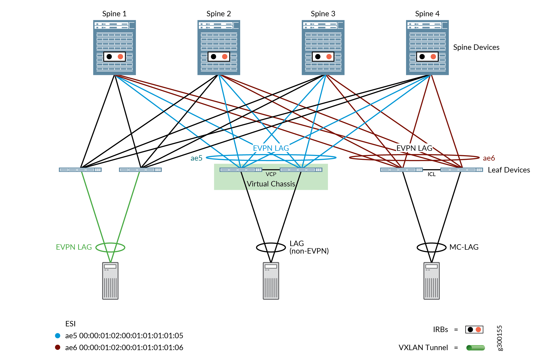
Figure 4 shows a Virtual Chassis and an MC-LAG architecture connected to spine devices using an EVPN LAG. The EVPN LAG provisioning is done from the spine devices during the migration of these topologies into an EVPN-VXLAN reference architecture.

The CRB Migration architecture is often used when migrating an MC-LAG or Virtual Chassis-based data center in phases. In this architecture, the EVPN LAG capability is introduced at the spine level and only one overlay iBGP session is running between the two spine switches. The top-of-rack switches connected to the spine devices are legacy switches configured as Virtual Chassis or MC-LAG clusters with no EVPN iBGP peerings to the spine switches.
This architecture helps when deploying EVPN-VXLAN technologies in stages into an existing data center. The first step is building an EVPN LAG-capable spine layer, and then sequentially migrating to an EVPN control plan where MAC addresses for the new leaf switches are learned from the spine layer switches. The new leaf switches, therefore, can benefit from the advanced EVPN features, such as ARP suppression, IGMP suppression, and optimized multicast, supported by the new switches.
The default EVPN core isolation behavior should be disabled
in CRB Migration architectures. The default EVPN core-isolation behavior
disables local EVPN LAG members if the network loses the last iBGP-EVPN
signaled peer. Because this peering between the two spine devices
will be lost during the migration, the default behavior-which can
be changed by entering the no-core-isolation option in
the edit protocols evpn hierarchy—must be changed
to prevent core isolation events.
