Virtual Private LAN Service Overview
Ethernet is an increasingly important component of a service provider’s slate of service offerings. Many customers are requesting the ability to connect LAN locations around the world. To fulfill customer needs, service providers have had to set up complex point-to-point Layer 2 virtual private networks (VPNs) or connect expensive Layer 2 switches to handle traffic.
Virtual private LAN service (VPLS) meets the growing Ethernet needs of service providers and their customers. VPLS is an Ethernet-based multipoint-to-multipoint Layer 2 VPN. With VPLS, multiple Ethernet LAN sites can be connected to each other across an MPLS backbone. To the customer, all sites interconnected by VPLS appear to be on the same Ethernet LAN (even though traffic travels across a service provider network).
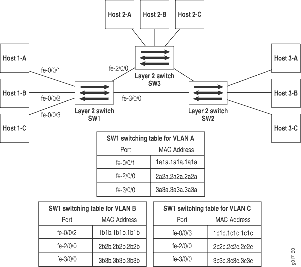
Before VPLS, the only way you could connect Ethernet LAN sites together was to set up a non-VPLS Layer 2 VPN or install multiple Layer 2 Ethernet switches. Figure 1 shows how three switches can be connected to each other.

A typical switch builds its Layer 2 switching table with media access control (MAC) address and interface information learned from traffic received from other switches. If a switch does not have an exit port associated with a particular destination, it floods traffic for that destination to all ports except the port where the traffic originated. When reachability information for a destination is received, this information is added to the switching table. If the switching table has an entry for the destination, the switch sends the traffic directly to the intended recipient through the associated port listed in the switching table.
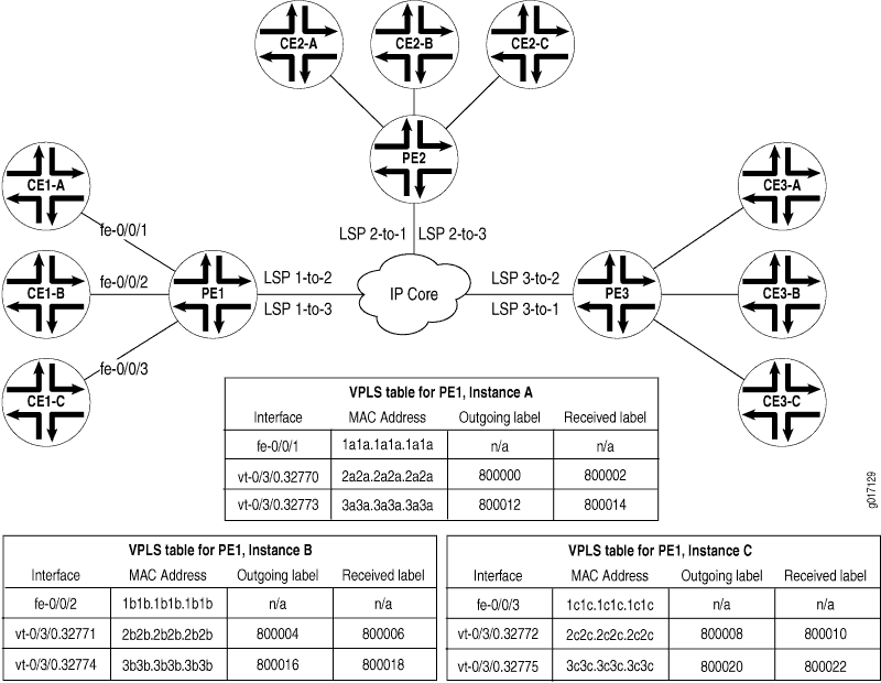
Figure 2 shows a VPLS network comparable to the switch example and explains how VPLS functions similarly to Ethernet switches (assuming a Spanning Tree Protocol (STP) is configured).

Notice that Layer 2 information gathered by a switch (for example, MAC addresses and interface ports) is included in the VPLS instance table. However, instead of requiring all VPLS interfaces to be physical switch ports, the router allows remote traffic for a VPLS instance to be delivered across an MPLS label-switched path (LSP) and arrive on a virtual port. The virtual port emulates a local, physical port. Traffic can be learned, forwarded, or flooded to the virtual port similar to the way traffic is sent to a local port.
The VPLS table learns MAC address and interface information for both physical and virtual ports. If no activity is seen for a particular MAC address, it is purged from the table over time.
As shown in Figure 2, the main difference between a physical port and a virtual port is that the router captures additional information from a virtual port—an outgoing MPLS label used to reach the remote site, and an incoming MPLS label for VPLS traffic received from the remote site.
When you configure VPLS on a routing platform,
a virtual port is generated as a logical interface on a virtual loopback tunnel (vt) interface or a label-switched
interface (LSI). On Juniper Networks M Series Multiservice Edge
Routers and Juniper Networks T Series Core Routers, virtual ports
are created dynamically on vt interfaces if you install
a PIC that supports virtual tunnels. With VPLS, you must install at
least one Tunnel Services, Link Services, or Adaptive Services PIC
in each VPLS provider edge (PE) router. On Juniper Networks MX Series
3D Universal Edge Routers, virtual ports are created dynamically on vt interfaces if you configure tunnel services on one of the
four Packet Forwarding Engines (PFEs) included in each Dense Port
Concentrator (DPC). If your routing platform does not offer tunnel
services through a PIC or PFE, you can configure VPLS to create virtual
ports on LSI logical interfaces.
One property of flooding behavior in VPLS is that traffic received from remote PE routers is never forwarded to other PE routers. This restriction helps prevent loops in the core network. If a customer edge (CE) Ethernet switch has redundant connections to the same PE router, you must enable the STP to prevent loops.
The paths that emulate a Layer 2 point-to-point connection over a packet-switched network are called pseudowires. The pseudowires are signaled using either BGP or LDP.
