Configuring Interworking Between BGP Signaling and LDP Signaling in VPLS Instances
If you want to configure a VPLS instance with both BGP and LDP-signaled pseudowires, you must configure a VPLS border router. Without a VPLS border router, LDP-signaled PEs and BGP-signaled PEs will be unaware of one another and the VPLS instance will not be fully meshed.
Interworking between BGP signaling and LDP signaling in VPLS instances is supported only on MX Series and M320 routers.
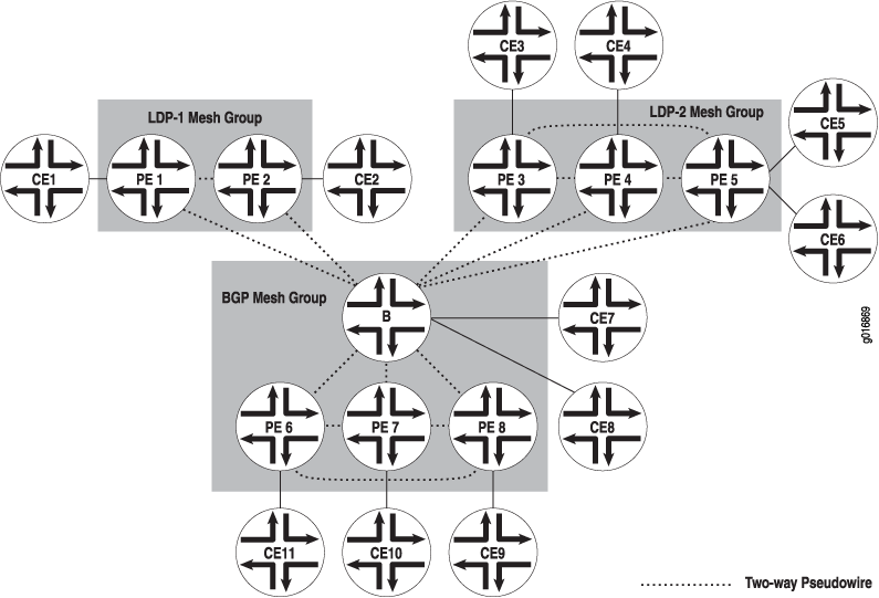
To enable interworking between BGP-signaled PE routers and LDP-signaled PE routers, you configure a border router to interconnect both sets of routers within the same VPLS routing instance. You also need to configure mesh groups on the border router to group the sets of PE routers that are fully meshed and which share the same signaling protocol, either BGP or LDP. You can configure multiple mesh groups to map each fully meshed LDP-signaled or BGP-signaled VPLS domain to a mesh group. In the data plane, the border router maintains a common MAC table used to forward traffic between the LDP-signaled and BGP-signaled mesh groups. When forwarding any VPLS traffic received over a PE router pseudowire, the border router ensures that traffic is not forwarded back to the PE routers, which are in same mesh group as the originating PE router.
There is always just one BGP mesh group in a VPLS instance, and it is created automatically when you configure BGP signaling for that instance. You can configure one or more LDP mesh groups. MX Series routers support up to 15 PE mesh groups (including the default BGP mesh group), and M Series and T Series routers support up to 127 PE mesh groups (including the default BGP mesh group).
In Figure 1, Routers PE1 and PE2
are in the LDP-signaled mesh group “LDP-1”. Routers PE3,
PE4, and PE5 are in the LDP-signaled mesh group “LDP-2”.
Routers PE6, PE7, and PE8 are in the BGP-signaled mesh group.
The border router acts as a traditional PE (by connecting to CEs)
in addition to being a border router. Every router shown in the topology
in Figure 1 is in the same VPLS instance, bgp-ldp-mesh1.
When Router CE1 sends a frame whose destination MAC address is CE9, PE1 receives the frame and performs a MAC address lookup. The MAC address is not in the PE1 MAC table and so PE1 floods the frame to the other PEs in the LDP-1 mesh group (PE2) and also to Router B, which from the perspective of PE1, are the only members of the VPLS network. When Router B receives the data from PE1, it does not find the MAC address in its MAC table and so it floods the frame to PE3, PE4, PE5, PE6, PE7, and PE8, but not back to PE1 or PE2. The PE routers then perform a MAC table lookup and flood the data to their CE routers.

In this topology, you configure routers PE6, PE7, and PE8 as
you traditionally configure BGP-signaled VPLS routers. You configure
routers PE1, PE2, PE3, PE4, and PE5 as you traditionally configure
LDP-signaled VPLS routers. In addition, you create the mesh group
LDP-1 for Routers PE1 and PE2 and mesh group LDP-2 for Routers PE3,
PE4, and PE5 by including the mesh-group mesh-group-name statement at the [edit routing-instances routing-instance-name protocols vpls] hierarchy level.
The border router can act as a normal PE in addition to being a border router and can support local CE-facing interfaces.
In the example below, the interfaces are CE interfaces. In this case, the router is acting as both a border router and a regular PE router.
To enable interworking between VPLS mesh groups, configure the
border router by including the site site-name statement at the [edit routing instances routing-instance-name protocols] hierarchy level:
[edit]
routing-instances {
    bgp-ldp-mesh1 {
        instance-type vpls;
        route-distinguisher 10.245.14.218:1;
        interface fe-1/3/1.0;
        interface fe-1/3/2.0;
    vrf-target target:10:100;
}
protocols {
    vpls {
    site green {
        site-identifier 1;
    }
}
Configure LDP signaling with the vpls-id and neighbor neighbor-id statements. You can
configure mesh groups LDP-1 and LDP-2 by including the mesh-group statement at the [edit routing instances routing-instance-name protocols vpls vpls-id and including
the neighbor neighbor-id statement
at the [edit routing-instances routing-instance-name protocols vpls mesh-group mesh-group-name] hierarchy level:
[edit routing-instances bgp-ldp-mesh1 protocols vpls]
vpls-id 100;
mesh-group LDP-1 {
    neighbor 10.1.1.1;
    neighbor 20.1.1.1;
}
mesh-group LDP-2 {
    neighbor 30.1.1.1;
    neighbor 40.1.1.1;
    neighbor 50.1.1.1;
}
When you configure BGP signaling to interoperate with LDP signaling in a VPLS network, the following features are not supported:
Point-to-multipoint VPLS
Integrated routing and bridging
