Example: Configuring an EVPN-VXLAN Deployment Using the Virtual Gateway Address
This example shows how to configure an Ethernet VPN (EVPN)-Virtual Extensible LAN (VXLAN) deployment using the virtual gateway address.
Requirements
This example uses the following hardware and software components:
Two MX960 3D Universal Edge Router gateways
Two top-of-rack (ToR) QFX5100 switches
Three end host devices
Junos OS Release 14.2 R6 or later (for MX960 routers)Junos OS Release 14.1X53-D30 or later (for QFX5100 switches)
Overview and Topology
Figure 1 shows a topology example for configuring the virtual gateway address in an EVPN-VXLAN deployment. It shows two QFX Series switches (192.168.0.122 and 192.168.0.125) (acting as ToRs, or leaf devices) providing Layer 2 gateway functionality, and two MX Series routers (192.168.0.212 and 192.168.0.210) functioning as spine devices and providing Layer 3 default gateway functionality.
This topology example assumes that the underlay has already been configured and is not shown in the diagram.
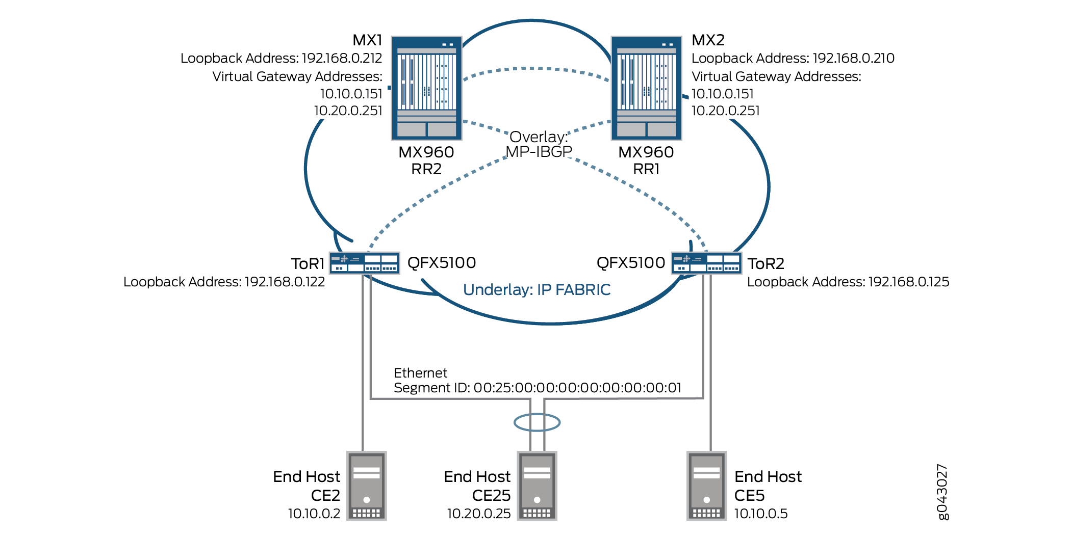
Sending pings to the virtual gateway IP address is currently not supported.
For the two MX Series routers, configure the following information:
IRB interfaces, virtual gateway addresses, and loopback logical interfaces.
Multiprotocol internal BGP (MP-IBGP) overlays between the spine and leaf devices, using BGP route reflection, and EVPN as the signaling protocol.
Routing policies to allow specific routes into the virtual-switch tables.
Routing instances (Layer 3 VRFs) for each virtual network, including a unique route distinguisher, and a vrf-target value.
Virtual-switch instances (Layer 2 MAC-VRFs) for each virtual network, the VTEP source interface (always lo0.0), route distinguisher, and vrf-import policy.
EVPN protocol, encapsulation method, VNI list, and BUM traffic forwarding method for each virtual switch.
Bridge domain within each virtual switch that maps VNIDs to VLAN IDs, an IRB (Layer 3) interface, and the BUM forwarding method.
For the two QFX Series switches (ToRs), configure the following information:
Host facing interfaces with VLANs, VLAN IDs, and loopback logical interfaces.
Link Aggregation Control Protocol (LACP)-enabled link aggregation group (LAG), Ethernet Segment ID (ESI), and all-active mode.
Multiprotocol internal BGP (MP-IBGP) overlays between the leaf and spine devices, and EVPN as the signaling protocol.
EVPN with VXLAN as the encapsulation method, extended-vni-list, multicast mode, and route targets for each VNI.
Vrf-imp policy, vtep-source-interface, route-distinguisher, and vrf import and target information.
VLANs, with VLAN IDs mapped to globally significant VNIs, and VXLAN ingress node replication.
You can set the virtual gateway address as the default IPv4 or IPv6 gateway address for end hosts (virtual machines or servers).
Configuration
This section provides step-by-step instructions for a complete configuration for an EVPN-VXLAN deployment with a virtual gateway address:
- Configuring Routing Instances and Bridge Domains for MX1
- Configuring Routing Instances and Bridge Domains for MX2
- Configuring Interfaces and VLANs for ToR1
- Configuring Interfaces and VLANs for ToR2
Configuring Routing Instances and Bridge Domains for MX1
CLI Quick Configuration
To quickly configure this example, copy the
following commands, paste them into a text file, remove any line breaks,
change any details necessary to match your network configuration,
copy and paste the commands into the CLI at the [edit] hierarchy
level, and then enter commit from configuration mode.
set interfaces irb unit 50 family inet address 10.10.0.101/24 virtual-gateway-address 10.10.0.151
set interfaces irb unit 51 family inet address 10.20.0.101/24 virtual-gateway-address 10.20.0.251
set interfaces lo0 unit 0 family inet address 192.168.0.212/32
set interfaces lo0.50 family inet address 192.168.50.213/32
set interfaces lo0.51 family inet address 192.198.51.214/32
set protocols bgp group overlay-evpn-rr description "Leaf/ToR1 and Leaf/ToR2"
set protocols bgp group overlay-evpn-rr type internal
set protocols bgp group overlay-evpn-rr local-address 192.168.0.212
set protocols bgp group overlay-evpn-rr family evpn signaling
set protocols bgp group overlay-evpn-rr cluster 10.10.10.10
set protocols bgp group overlay-evpn-rr local-as 65200
set protocols bgp group overlay-evpn-rr multipath
set protocols bgp group overlay-evpn-rr neighbor 192.168.0.122
set protocols bgp group overlay-evpn-rr neighbor 192.168.0.125
set protocols bgp group overlay-evpn description "to MX2/Spine2"
set protocols bgp group overlay-evpn type internal
set protocols bgp group overlay-evpn local-address 192.168.0.212
set protocols bgp group overlay-evpn family evpn signaling
set protocols bgp group overlay-evpn local-as 65200
set protocols bgp group overlay-evpn multipath
set protocols bgp group overlay-evpn neighbor 192.168.0.210
set policy-options policy-statement VS_VLAN50_IMP term ESI from community comm-leaf_esi
set policy-options policy-statement VS_VLAN50_IMP term ESI then accept
set policy-options policy-statement VS_VLAN50_IMP term VS_VLAN50 from community comm-VS_VLAN50
set policy-options policy-statement VS_VLAN50_IMP term VS_VLAN50 then accept
set policy-options policy-statement VS_VLAN51_IMP term ESI from community comm-leaf_esi
set policy-options policy-statement VS_VLAN51_IMP term ESI then accept
set policy-options policy-statement VS_VLAN51_IMP term VS_VLAN51 from community comm-VS_VLAN51
set policy-options policy-statement VS_VLAN51_IMP term VS_VLAN51 then accept
set policy-options community comm-VS_VLAN50 members target:1:50
set policy-options community comm-VS_VLAN51 members target:1:51
set policy-options community comm-leaf_esi members target:9999:9999
set routing-instances VRF_50 instance-type vrf
set routing-instances VRF_50 interface lo0.50
set routing-instances VRF_50 interface irb.50
set routing-instances VRF_50 route-distinguisher 192.168.0.212:500
set routing-instances VRF_50 vrf-target target:10:500
set routing-instances VRF_51 instance-type vrf
set routing-instances VRF_51 interface lo0.51
set routing-instances VRF_51 interface irb.51
set routing-instances VRF_51 route-distinguisher 192.168.0.212:510
set routing-instances VRF_51 vrf-target target:10:510
set routing-instances VS_VLAN50 instance-type virtual-switch
set routing-instances VS_VLAN50 vtep-source-interface lo0.0
set routing-instances VS_VLAN50 route-distinguisher 192.168.0.212:50
set routing-instances VS_VLAN50 vrf-import VS_VLAN50_IMP
set routing-instances VS_VLAN50 vrf-target target:1:50
set routing-instances VS_VLAN50 protocols evpn encapsulation vxlan
set routing-instances VS_VLAN50 protocols evpn extended-vni-list 50
set routing-instances VS_VLAN50 protocols evpn multicast-mode ingress-replication
set routing-instances VS_VLAN50 protocols evpn default-gateway no-gateway-community
set routing-instances VS_VLAN50 bridge-domains bd50 vlan-id 50
set routing-instances VS_VLAN50 bridge-domains bd50 routing-interface irb.50
set routing-instances VS_VLAN50 bridge-domains bd50 vxlan vni 50
set routing-instances VS_VLAN50 bridge-domains bd50 vxlan ingress-node-replication
set routing-instances VS_VLAN51 instance-type virtual-switch
set routing-instances VS_VLAN51 vtep-source-interface lo0.0
set routing-instances VS_VLAN51 route-distinguisher 192.168.0.212:51
set routing-instances VS_VLAN51 vrf-import VS_VLAN51_IMP
set routing-instances VS_VLAN51 vrf-target target:1:51
set routing-instances VS_VLAN51 protocols evpn encapsulation vxlan
set routing-instances VS_VLAN51 protocols evpn extended-vni-list 51
set routing-instances VS_VLAN51 protocols evpn multicast-mode ingress-replication
set routing-instances VS_VLAN51 protocols evpn default-gateway no-gateway-community
set routing-instances VS_VLAN51 bridge-domains bd51 vlan-id 51
set routing-instances VS_VLAN51 bridge-domains bd51 routing-interface irb.51
set routing-instances VS_VLAN51 bridge-domains bd51 vxlan vni 51
set routing-instances VS_VLAN51 bridge-domains bd51 vxlan ingress-node-replication
Step-by-Step Procedure
The following example requires that you navigate various levels in the configuration hierarchy. For information about navigating the CLI, see Using the CLI Editor in Configuration Mode in the CLI User Guide.
Configure an integrated routing and bridging (IRB) interface for each of the two virtual networks (VNs), including a virtual gateway address to act as a common MAC address and IP address across both MX Series (spine) devices.
[edit interfaces]
user@MX1# set irb unit 50 family inet address 10.10.0.101/24 virtual-gateway-address 10.10.0.151
user@MX1# set irb unit 51 family inet address 10.20.0.101/24 virtual-gateway-address 10.20.0.251
Configure the loopback interface.
[edit interfaces]
user@MX1# set lo0 unit 0 family inet address 192.168.0.212/32
user@MX1# set lo0.50 family inet address 192.168.50.213/32
user@MX1# set lo0.51 family inet address 192.198.51.214/32
Configure a multiprotocol internal BGP (MP-IBGP) overlay between the spine and leaf devices, using BGP route reflection, and set EVPN as the signaling protocol.
[edit protocols]
user@MX1# set bgp group overlay-evpn-rr description "to Leaf/ToR1 and Leaf/ToR2"
user@MX1# set bgp group overlay-evpn-rr type internal
user@MX1# set bgp group overlay-evpn-rr local-address 192.168.0.212
user@MX1# set bgp group overlay-evpn-rr family evpn signaling
user@MX1# set bgp group overlay-evpn-rr cluster 10.10.10.10
user@MX1# set bgp group overlay-evpn-rr local-as 65200
user@MX1# set bgp group overlay-evpn-rr multipath
user@MX1# set bgp group overlay-evpn-rr neighbor 192.168.0.122
user@MX1# set bgp group overlay-evpn-rr neighbor 192.168.0.125
Configure a second MP-IBGP overlay to connect the spine devices to each other using EVPN signaling.
[edit protocols]
user@MX1# set bgp group overlay-evpn description "to MX2/Spine2"
user@MX1# set bgp group overlay-evpn type internal
user@MX1# set bgp group overlay-evpn local-address 192.168.0.212
user@MX1# set bgp group overlay-evpn family evpn signaling
user@MX1# set bgp group overlay-evpn local-as 65200
user@MX1# set bgp group overlay-evpn multipath
user@MX1# set bgp group overlay-evpn neighbor 192.168.0.210
Configure routing policies to allow specific routes into the virtual-switch tables. Ensure that the policy includes target 9999:9999 so that the virtual switches import the Type-1 Ethernet Segment ID (ESI) routes from the ToR/Leaf devices.
[edit policy-options]
user@MX1# set policy-statement VS_VLAN50_IMP term ESI from community comm-leaf_esi
user@MX1# set policy-statement VS_VLAN50_IMP term ESI then accept
user@MX1# set policy-statement VS_VLAN50_IMP term VS_VLAN50 from community comm-VS_VLAN50
user@MX1# set policy-statement VS_VLAN50_IMP term VS_VLAN50 then accept
user@MX1# set policy-statement VS_VLAN51_IMP term ESI from community comm-leaf_esi
user@MX1# set policy-statement VS_VLAN51_IMP term ESI then accept
user@MX1# set policy-statement VS_VLAN51_IMP term VS_VLAN51 from community comm-VS_VLAN51
user@MX1# set policy-statement VS_VLAN51_IMP term VS_VLAN51 then accept
user@MX1# set community comm-VS_VLAN50 members target:1:50
user@MX1# set community comm-VS_VLAN51 members target:1:51
user@MX1# set community comm-leaf_esi members target:9999:9999
Configure routing instances (Layer 3 VRFs) for each virtual network. Assign each routing instance a unique route distinguisher, associate the appropriate IRB interface, and assign a vrf-target value.
[edit routing-instances]
user@MX1# set VRF_50 instance-type vrf
user@MX1# set VRF_50 interface lo0.50
user@MX1# set VRF_50 interface irb.50
user@MX1# set VRF_50 route-distinguisher 192.168.0.212:500
user@MX1# set VRF_50 vrf-target target:10:500
user@MX1# set VRF_51 instance-type vrf
user@MX1# set VRF_51 interface lo0.51
user@MX1# set VRF_51 interface irb.51
user@MX1# set VRF_51 route-distinguisher 192.168.0.212:510
user@MX1# set VRF_51 vrf-target target:10:510
Configure virtual-switch instances (Layer 2 MAC-VRFs) for each virtual network. Define the VTEP source interface (always lo0.0), route distinguisher (used to identify and advertise EVPN routes), vrf-import policy (defines which route targets to import into the virtual switches’ EVPN tables), and vrf-target (exports and tags all routes for that local VRF using the defined route target). Then for each virtual switch, configure the EVPN protocol, encapsulation method, VNI list, and BUM traffic forwarding method. Finally, configure a bridge domain for each virtual switch that maps VNIDs to VLAN IDs, associate an IRB (Layer 3) interface, and identify the BUM forwarding method.
[edit routing-instances]
user@MX1# set VS_VLAN50 instance-type virtual-switch
user@MX1# set VS_VLAN50 vtep-source-interface lo0.0
user@MX1# set VS_VLAN50 route-distinguisher 192.168.0.212:50
user@MX1# set VS_VLAN50 vrf-import VS_VLAN50_IMP
user@MX1# set VS_VLAN50 vrf-target target:1:50
user@MX1# set VS_VLAN50 protocols evpn encapsulation vxlan
user@MX1# set VS_VLAN50 protocols evpn extended-vni-list 50
user@MX1# set VS_VLAN50 protocols evpn multicast-mode ingress-replication
user@MX1# set VS_VLAN50 protocols evpn default-gateway no-gateway-community
user@MX1# set VS_VLAN50 bridge-domains bd50 vlan-id 50
user@MX1# set VS_VLAN50 bridge-domains bd50 routing-interface irb.50
user@MX1# set VS_VLAN50 bridge-domains bd50 vxlan vni 50
user@MX1# set VS_VLAN50 bridge-domains bd50 vxlan ingress-node-replication
user@MX1# set VS_VLAN51 instance-type virtual-switch
user@MX1# set VS_VLAN51 vtep-source-interface lo0.0
user@MX1# set VS_VLAN51 route-distinguisher 192.168.0.212:51
user@MX1# set VS_VLAN51 vrf-import VS_VLAN51_IMP
user@MX1# set VS_VLAN51 vrf-target target:1:51
user@MX1# set VS_VLAN51 protocols evpn encapsulation vxlan
user@MX1# set VS_VLAN51 protocols evpn extended-vni-list 51
user@MX1# set VS_VLAN51 protocols evpn multicast-mode ingress-replication
user@MX1# set VS_VLAN51 protocols evpn default-gateway no-gateway-community
user@MX1# set VS_VLAN51 bridge-domains bd51 vlan-id 51
user@MX1# set VS_VLAN51 bridge-domains bd51 routing-interface irb.51
user@MX1# set VS_VLAN51 bridge-domains bd51 vxlan vni 51
user@MX1# set VS_VLAN51 bridge-domains bd51 vxlan ingress-node-replication
Configuring Routing Instances and Bridge Domains for MX2
CLI Quick Configuration
To quickly configure this example, copy the
following commands, paste them into a text file, remove any line breaks,
change any details necessary to match your network configuration,
copy and paste the commands into the CLI at the [edit] hierarchy
level, and then enter commit from configuration mode.
set interfaces irb unit 50 family inet address 10.10.0.104/24 virtual-gateway-address 10.10.0.151
set interfaces irb unit 51 family inet address 10.20.0.104/24 virtual-gateway-address 10.20.0.251
set interfaces lo0 unit 0 family inet address 192.168.0.210/32
set interfaces lo0.50 family inet address 192.168.50.208/32
set interfaces lo0.51 family inet address 192.168.51.209/32
set protocols bgp group overlay-evpn-rr description "to Leaf/ToR1 and Leaf/ToR2"
set protocols bgp group overlay-evpn-rr type internal
set protocols bgp group overlay-evpn-rr local-address 192.168.0.210
set protocols bgp group overlay-evpn-rr family evpn signaling
set protocols bgp group overlay-evpn-rr cluster 10.10.10.10
set protocols bgp group overlay-evpn-rr local-as 65200
set protocols bgp group overlay-evpn-rr multipath
set protocols bgp group overlay-evpn-rr neighbor 192.168.0.122
set protocols bgp group overlay-evpn-rr neighbor 192.168.0.125
set protocols bgp group overlay-evpn description "to MX1/Spine1"
set protocols bgp group overlay-evpn type internal
set protocols bgp group overlay-evpn local-address 192.168.0.210
set protocols bgp group overlay-evpn family evpn signaling
set protocols bgp group overlay-evpn local-as 65200
set protocols bgp group overlay-evpn multipath
set protocols bgp group overlay-evpn neighbor 192.168.0.212
set policy-options policy-statement VS_VLAN50_IMP term ESI from community comm-leaf_esi
set policy-options policy-statement VS_VLAN50_IMP term ESI then accept
set policy-options policy-statement VS_VLAN50_IMP term VS_VLAN50 from community comm-VS_VLAN50
set policy-options policy-statement VS_VLAN50_IMP term VS_VLAN50 then accept
set policy-options policy-statement VS_VLAN51_IMP term ESI from community comm-leaf_esi
set policy-options policy-statement VS_VLAN51_IMP term ESI then accept
set policy-options policy-statement VS_VLAN51_IMP term VS_VLAN51 from community comm-VS_VLAN51
set policy-options policy-statement VS_VLAN51_IMP term VS_VLAN51 then accept
set policy-options community comm-VS_VLAN50 members target:1:50
set policy-options community comm-VS_VLAN51 members target:1:51
set policy-options community comm-leaf_esi members target:9999:9999
set routing-instances VRF_50 instance-type vrf
set routing-instances VRF_50 interface lo0.50
set routing-instances VRF_50 interface irb.50
set routing-instances VRF_50 route-distinguisher 192.168.0.210:500
set routing-instances VRF_50 vrf-target target:10:500
set routing-instances VRF_51 instance-type vrf
set routing-instances VRF_51 interface lo0.51
set routing-instances VRF_51 interface irb.51
set routing-instances VRF_51 route-distinguisher 192.168.0.210:510
set routing-instances VRF_51 vrf-target target:10:510
set routing-instances VS_VLAN50 instance-type virtual-switch
set routing-instances VS_VLAN50 vtep-source-interface lo0.0
set routing-instances VS_VLAN50 route-distinguisher 192.168.0.210:50
set routing-instances VS_VLAN50 vrf-import VS_VLAN50_IMP
set routing-instances VS_VLAN50 vrf-target target:1:50
set routing-instances VS_VLAN50 protocols evpn encapsulation vxlan
set routing-instances VS_VLAN50 protocols evpn extended-vni-list 50
set routing-instances VS_VLAN50 protocols evpn multicast-mode ingress-replication
set routing-instances VS_VLAN50 protocols evpn default-gateway no-gateway-community
set routing-instances VS_VLAN50 bridge-domains bd50 vlan-id 50
set routing-instances VS_VLAN50 bridge-domains bd50 routing-interface irb.50
set routing-instances VS_VLAN50 bridge-domains bd50 vxlan vni 50
set routing-instances VS_VLAN50 bridge-domains bd50 vxlan ingress-node-replication
set routing-instances VS_VLAN51 instance-type virtual-switch
set routing-instances VS_VLAN51 vtep-source-interface lo0.0
set routing-instances VS_VLAN51 route-distinguisher 192.168.0.210:51
set routing-instances VS_VLAN51 vrf-import VS_VLAN51_IMP
set routing-instances VS_VLAN51 vrf-target target:1:51
set routing-instances VS_VLAN51 protocols evpn encapsulation vxlan
set routing-instances VS_VLAN51 protocols evpn extended-vni-list 51
set routing-instances VS_VLAN51 protocols evpn multicast-mode ingress-replication
set routing-instances VS_VLAN51 protocols evpn default-gateway no-gateway-community
set routing-instances VS_VLAN51 bridge-domains bd51 vlan-id 51
set routing-instances VS_VLAN51 bridge-domains bd51 routing-interface irb.51
set routing-instances VS_VLAN51 bridge-domains bd51 vxlan vni 51
set routing-instances VS_VLAN51 bridge-domains bd51 vxlan ingress-node-replication
Step-by-Step Procedure
The following example requires that you navigate various levels in the configuration hierarchy. For information about navigating the CLI, see Using the CLI Editor in Configuration Mode in the CLI User Guide.
Configure an integrated routing and bridging (IRB) interface for each of the two virtual networks (VNs), including a virtual gateway address to act as a common MAC address and IP address across both MX Series (spine) devices.
[edit interfaces]
user@MX2# set irb unit 50 family inet address 10.10.0.104/24 virtual-gateway-address 10.10.0.151
user@MX2# set irb unit 51 family inet address 10.20.0.104/24 virtual-gateway-address 10.20.0.251
Configure the loopback interface.
[edit interfaces]
user@MX2# set lo0 unit 0 family inet address 192.168.0.210/32
user@MX2# set lo0.50 family inet address 192.168.50.208/32
user@MX2# set lo0.51 family inet address 192.168.51.209/32
Configure a multiprotocol internal BGP (MP-IBGP) overlay between the spine and leaf devices, using BGP route reflection, and set EVPN as the signaling protocol.
[edit protocols]
user@MX2# set bgp group overlay-evpn-rr description "to Leaf/ToR1 and Leaf/ToR2"
user@MX2# set bgp group overlay-evpn-rr type internal
user@MX2# set bgp group overlay-evpn-rr local-address 192.168.0.210
user@MX2# set bgp group overlay-evpn-rr family evpn signaling
user@MX2# set bgp group overlay-evpn-rr cluster 10.10.10.10
user@MX2# set bgp group overlay-evpn-rr local-as 65200
user@MX2# set bgp group overlay-evpn-rr multipath
user@MX2# set bgp group overlay-evpn-rr neighbor 192.168.0.122
user@MX2# set bgp group overlay-evpn-rr neighbor 192.168.0.125
Configure a second MP-IBGP overlay to connect the spine devices to each other using EVPN signaling.
[edit protocols]
user@MX2# set bgp group overlay-evpn description "to MX1/Spine1"
user@MX2# set bgp group overlay-evpn type internal
user@MX2# set bgp group overlay-evpn local-address 192.168.0.210
user@MX2# set bgp group overlay-evpn family evpn signaling
user@MX2# set bgp group overlay-evpn local-as 65200
user@MX2# set bgp group overlay-evpn multipath
user@MX2# set bgp group overlay-evpn neighbor 192.168.0.212
Configure routing policies to allow specific routes into the virtual-switch tables. Ensure that the policy includes target 9999:9999 so that the virtual switches import the Type-1 Ethernet Segment ID (ESI) routes from the ToR/Leaf devices.
[edit policy-options]
user@MX2# set policy-statement VS_VLAN50_IMP term ESI from community comm-leaf_esi
user@MX2# set policy-statement VS_VLAN50_IMP term ESI then accept
user@MX2# set policy-statement VS_VLAN50_IMP term VS_VLAN50 from community comm-VS_VLAN50
user@MX2# set policy-statement VS_VLAN50_IMP term VS_VLAN50 then accept
user@MX2# set policy-statement VS_VLAN51_IMP term ESI from community comm-leaf_esi
user@MX2# set policy-statement VS_VLAN51_IMP term ESI then accept
user@MX2# set policy-statement VS_VLAN51_IMP term VS_VLAN51 from community comm-VS_VLAN51
user@MX2# set policy-statement VS_VLAN51_IMP term VS_VLAN51 then accept
user@MX2# set community comm-VS_VLAN50 members target:1:50
user@MX2# set community comm-VS_VLAN51 members target:1:51
user@MX2# set community comm-leaf_esi members target:9999:9999
Configure routing instances (Layer 3 VRFs) for each virtual network. Assign each routing instance a unique route distinguisher, associate the appropriate IRB interface, and assign a vrf-target value.
[edit routing-instances]
user@MX2# set VRF_50 instance-type vrf
user@MX2# set VRF_50 interface lo0.50
user@MX2# set VRF_50 interface irb.50
user@MX2# set VRF_50 route-distinguisher 192.168.0.210:500
user@MX2# set VRF_50 vrf-target target:10:500
user@MX2# set VRF_51 instance-type vrf
user@MX2# set VRF_51 interface lo0.51
user@MX2# set VRF_51 interface irb.51
user@MX2# set VRF_51 route-distinguisher 192.168.0.210:510
user@MX2# set VRF_51 vrf-target target:10:510
Configure virtual-switch instances (Layer 2 MAC-VRFs) for each virtual network. Define the VTEP source interface (always lo0.0), route distinguisher (used to identify and advertise EVPN routes), vrf-import policy (defines which route targets to import into the virtual switches’ EVPN tables), and vrf-target (exports and tags all routes for that local VRF using the defined route target). Then for each virtual switch, configure the EVPN protocol, encapsulation method, VNI list, and BUM traffic forwarding method. Finally, configure a bridge domain for each virtual switch that maps VNIDs to VLAN IDs, associate an IRB (Layer 3) interface, and identify the BUM forwarding method.
[edit routing-instances]
user@MX2# set VS_VLAN50 instance-type virtual-switch
user@MX2# set VS_VLAN50 vtep-source-interface lo0.0
user@MX2# set VS_VLAN50 route-distinguisher 192.168.0.210:50
user@MX2# set VS_VLAN50 vrf-import VS_VLAN50_IMP
user@MX2# set VS_VLAN50 vrf-target target:1:50
user@MX2# set VS_VLAN50 protocols evpn encapsulation vxlan
user@MX2# set VS_VLAN50 protocols evpn extended-vni-list 50
user@MX2# set VS_VLAN50 protocols evpn multicast-mode ingress-replication
user@MX2# set VS_VLAN50 protocols evpn default-gateway no-gateway-community
user@MX2# set VS_VLAN50 bridge-domains bd50 vlan-id 50
user@MX2# set VS_VLAN50 bridge-domains bd50 routing-interface irb.50
user@MX2# set VS_VLAN50 bridge-domains bd50 vxlan vni 50
user@MX2# set VS_VLAN50 bridge-domains bd50 vxlan ingress-node-replication
user@MX2# set VS_VLAN51 instance-type virtual-switch
user@MX2# set VS_VLAN51 vtep-source-interface lo0.0
user@MX2# set VS_VLAN51 route-distinguisher 192.168.0.210:51
user@MX2# set VS_VLAN51 vrf-import VS_VLAN51_IMP
user@MX2# set VS_VLAN51 vrf-target target:1:51
user@MX2# set VS_VLAN51 protocols evpn encapsulation vxlan
user@MX2# set VS_VLAN51 protocols evpn extended-vni-list 51
user@MX2# set VS_VLAN51 protocols evpn multicast-mode ingress-replication
user@MX2# set VS_VLAN51 protocols evpn default-gateway no-gateway-community
user@MX2# set VS_VLAN51 bridge-domains bd51 vlan-id 51
user@MX2# set VS_VLAN51 bridge-domains bd51 routing-interface irb.51
user@MX2# set VS_VLAN51 bridge-domains bd51 vxlan vni 51
user@MX2# set VS_VLAN51 bridge-domains bd51 vxlan ingress-node-replication
Configuring Interfaces and VLANs for ToR1
CLI Quick Configuration
To quickly configure this example, copy the
following commands, paste them into a text file, remove any line breaks,
change any details necessary to match your network configuration,
copy and paste the commands into the CLI at the [edit] hierarchy
level, and then enter commit from configuration mode.
set interfaces ge-1/1/0 description "to CE2"
set interfaces ge-1/1/0 unit 0 family ethernet-switching vlan members v50
set interfaces ge-1/1/2 description "to CE25"
set interfaces ge-1/1/2 ether-options 802.3ad ae0
set interfaces ae0 esi 00:25:00:00:00:00:00:00:00:01
set interfaces ae0 esi all-active
set interfaces ae0 aggregated-ether-options lacp active
set interfaces ae0 aggregated-ether-options lacp system-id 00:00:00:01:01:01
set interfaces ae0 unit 0 family ethernet-switching vlan members v51
set interfaces lo0 unit 0 family inet address 192.168.0.122/32
set protocols bgp group overlay-evpn description "to MX1/Spine1 and MX2/Spine2"
set protocols bgp group overlay-evpn type internal
set protocols bgp group overlay-evpn local-address 192.168.0.122
set protocols bgp group overlay-evpn family evpn signaling
set protocols bgp group overlay-evpn local-as 65200
set protocols bgp group overlay-evpn multipath
set protocols bgp group overlay-evpn neighbor 192.168.0.212
set protocols bgp group overlay-evpn neighbor 192.168.0.210
set protocols evpn encapsulation vxlan
set protocols evpn extended-vni-list 50
set protocols evpn extended-vni-list 51
set protocols evpn multicast-mode ingress-replication
set protocols evpn vni-options vni 50 vrf-target export target:1:50
set protocols evpn vni-options vni 51 vrf-target export target:1:51
set policy-options policy-statement vrf-imp term t1 from community comm-leaf_esi
set policy-options policy-statement vrf-imp term t1 then accept
set policy-options policy-statement vrf-imp term t2 from community com50
set policy-options policy-statement vrf-imp term t2 then accept
set policy-options policy-statement vrf-imp term t3 from community com51
set policy-options policy-statement vrf-imp term t3 then accept
set policy-options policy-statement vrf-imp term t4 then reject
set policy-options community comm-leaf_esi members target:9999:9999
set policy-options community com50 members target:1:50
set policy-options community com51 members target:1:51
set switch-options vtep-source-interface lo0.0
set switch-options route-distinguisher 192.168.0.122:1
set switch-options vrf-import vrf-imp
set switch-options vrf-target target:9999:9999
set vlans v50 vlan-id 50
set vlans v50 vxlan vni 50
set vlans v50 vxlan ingress-node-replication
set vlans v51 vlan-id 51
set vlans v51 vxlan vni 51
set vlans v51 vxlan ingress-node-replication
Step-by-Step Procedure
The following example requires that you navigate various levels in the configuration hierarchy. For information about navigating the CLI, see Using the CLI Editor in Configuration Mode in the CLI User Guide.
Create and configure the host-facing interface towards the CE2 end host device, and configure its VLAN information.
[edit interfaces]
user@ToR1# set ge-1/1/0 description "to CE2"
user@ToR1# set ge-1/1/0 unit 0 family ethernet-switching vlan members v50
Create and configure the host-facing interface towards the CE25 end host device, and configure it as a member of the aggregated Ethernet bundle ae0.
[edit interfaces]
user@ToR1# set ge-1/1/2 description "to CE25"
user@ToR1# set ge-1/1/2 ether-options 802.3ad ae0
Configure a Link Aggregation Control Protocol (LACP)-enabled link aggregation group (LAG) interface towards the CE25 end host device. The Ethernet Segment ID (ESI) is globally unique across the entire EVPN domain. The all-active configuration enables both ToR1 and ToR2 to forward traffic to, and from the CE25 end host device.
[edit interfaces]
user@ToR1# set ae0 esi 00:25:00:00:00:00:00:00:00:01
user@ToR1# set ae0 esi all-active
user@ToR1# set ae0 aggregated-ether-options lacp active
user@ToR1# set ae0 aggregated-ether-options lacp system-id 00:00:00:01:01:01
user@ToR1# set ae0 unit 0 family ethernet-switching vlan members v51
Configure the loopback interface.
[edit interfaces]
user@ToR1#  set lo0 unit 0 family inet address 192.168.0.122/32
Configure a multiprotocol internal BGP (MP-IBGP) overlay between the leaf and spine devices and configure EVPN as the signaling protocol.
[edit protocols]
user@ToR1# set bgp group overlay-evpn description "to MX1/Spine1 and MX2/Spine2"
user@ToR1# set bgp group overlay-evpn type internal
user@ToR1# set bgp group overlay-evpn local-address 192.168.0.122
user@ToR1# set bgp group overlay-evpn family evpn signaling
user@ToR1# set bgp group overlay-evpn local-as 65200
user@ToR1# set bgp group overlay-evpn multipath
user@ToR1# set bgp group overlay-evpn neighbor 192.168.0.212
user@ToR1# set bgp group overlay-evpn neighbor 192.168.0.210
Configure EVPN using VXLAN as the encapsulation method, configure the extended-vni-list to establish which VNIs are part of the EVPN-VXLAN MP-BGP domain, set the multicast mode to use ingress-replication (instead of using a multicast underlay), and then configure route targets for each VNI under vni-options.
[edit protocols]
user@ToR1# set evpn encapsulation vxlan
user@ToR1# set evpn extended-vni-list 50
user@ToR1# set evpn extended-vni-list 51
user@ToR1# set evpn multicast-mode ingress-replication
user@ToR1# set evpn vni-options vni 50 vrf-target export target:1:50
user@ToR1# set evpn vni-options vni 51 vrf-target export target:1:51
Configure the vrf-imp policy to identify and permit the target communities to be imported into the default-switch.evpn.0 instance from bgp.evpn.0.
[edit policy-options]
user@ToR1# set policy-statement vrf-imp term t1 from community comm-leaf_esi
user@ToR1# set policy-statement vrf-imp term t1 then accept
user@ToR1# set policy-statement vrf-imp term t2 from community com50
user@ToR1# set policy-statement vrf-imp term t2 then accept
user@ToR1# set policy-statement vrf-imp term t3 from community com51
user@ToR1# set policy-statement vrf-imp term t3 then accept
user@ToR1# set policy-statement vrf-imp term t4 then reject
user@ToR1# set community comm-leaf_esi members target:9999:9999
user@ToR1# set community com50 members target:1:50
user@ToR1# set community com51 members target:1:51
Configure the vtep-source-interface (which is always set to lo0.0), the route-distinguisher, and vrf import and target information.
Note:The route-distinguisher must be unique, network-wide, across all switches to ensure all route advertisements within MP-BGP are globally unique. The vrf-target tags outbound routing information for the switch, including (at a minimum) all ESI (Type-1) routes. The
vrf-importstatement references the vrf-imp policy to allow inbound routing information from remote devices.[edit switch-options] user@ToR1# set vtep-source-interface lo0.0 user@ToR1# set route-distinguisher 192.168.0.122:1 user@ToR1# set vrf-import vrf-imp user@ToR1# set vrf-target target:9999:9999
Define the VLANs, map locally significant VLAN IDs to globally significant VNIs, and set VXLAN ingress node replication.
[edit vlans]
user@ToR1# set v50 vlan-id 50
user@ToR1# set v50 vxlan vni 50
user@ToR1# set v50 vxlan ingress-node-replication
user@ToR1# set v51 vlan-id 51
user@ToR1# set v51 vxlan vni 51
user@ToR1# set v51 vxlan ingress-node-replication
Configuring Interfaces and VLANs for ToR2
CLI Quick Configuration
To quickly configure this example, copy the
following commands, paste them into a text file, remove any line breaks,
change any details necessary to match your network configuration,
copy and paste the commands into the CLI at the [edit] hierarchy
level, and then enter commit from configuration mode.
set interfaces ge-1/1/0 description "to CE5"
set interfaces ge-1/1/0 unit 0 family ethernet-switching vlan members v50
set interfaces ge-1/1/2 description "to CE25"
set interfaces ge-1/1/2 ether-options 802.3ad ae0
set interfaces ae0 esi 00:25:00:00:00:00:00:00:00:01
set interfaces ae0 esi all-active
set interfaces ae0 aggregated-ether-options lacp active
set interfaces ae0 aggregated-ether-options lacp system-id 00:00:00:01:01:01
set interfaces ae0 unit 0 family ethernet-switching vlan members v51
set interfaces lo0 unit 0 family inet address 192.168.0.125/32
set protocols bgp group overlay-evpn description "to MX1/Spine1 and MX2/Spine2"
set protocols bgp group overlay-evpn type internal
set protocols bgp group overlay-evpn local-address 192.168.0.125
set protocols bgp group overlay-evpn family evpn signaling
set protocols bgp group overlay-evpn local-as 65200
set protocols bgp group overlay-evpn multipath
set protocols bgp group overlay-evpn neighbor 192.168.0.212
set protocols bgp group overlay-evpn neighbor 192.168.0.210
set protocols evpn encapsulation vxlan
set protocols evpn extended-vni-list 50
set protocols evpn extended-vni-list 51
set protocols evpn multicast-mode ingress-replication
set protocols evpn vni-options vni 50 vrf-target export target:1:50
set protocols evpn vni-options vni 51 vrf-target export target:1:51
set policy-options policy-statement vrf-imp term t1 from community comm-leaf_esi
set policy-options policy-statement vrf-imp term t1 then accept
set policy-options policy-statement vrf-imp term t2 from community com50
set policy-options policy-statement vrf-imp term t2 then accept
set policy-options policy-statement vrf-imp term t3 from community com51
set policy-options policy-statement vrf-imp term t3 then accept
set policy-options policy-statement vrf-imp term t4 then reject
set policy-options community comm-leaf_esi members target:9999:9999
set policy-options community com50 members target:1:50
set policy-options community com50 members target:1:50
set policy-options community com51 members target:1:51
set switch-options vtep-source-interface lo0.0
set switch-options route-distinguisher 192.168.0.125:1
set switch-options vrf-import vrf-imp
set switch-options vrf-target target:9999:9999
set vlans v50 vlan-id 50
set vlans v50 vxlan vni 50
set vlans v50 vxlan ingress-node-replication
set vlans v51 vlan-id 51
set vlans v51 vxlan vni 51
set vlans v51 vxlan ingress-node-replication
Step-by-Step Procedure
The following example requires that you navigate various levels in the configuration hierarchy. For information about navigating the CLI, see Using the CLI Editor in Configuration Mode in the CLI User Guide.
Create and configure the host-facing interface towards the CE5 end host device, and configure its VLAN information.
[edit interfaces]
user@ToR2# set ge-1/1/0 description "to CE5"
user@ToR2# set ge-1/1/0 unit 0 family ethernet-switching vlan members v50
Create and configure the host-facing interface towards the CE25 end host device, and configure it as a member of the aggregated Ethernet bundle ae0.
[edit interfaces]
user@ToR2# set ge-1/1/2 description "to CE25"
user@ToR2# set ge-1/1/2 ether-options 802.3ad ae0
Configure a Link Aggregation Control Protocol (LACP)-enabled link aggregation group (LAG) interface towards the CE25 end host device. The Ethernet Segment ID (ESI) is globally unique across the entire EVPN domain. The all-active configuration enables both ToR1 and ToR2 to forward traffic to, and from the CE25 end host device.
[edit interfaces]
user@ToR2# set ae0 esi 00:25:00:00:00:00:00:00:00:01
user@ToR2# set ae0 esi all-active
user@ToR2# set ae0 aggregated-ether-options lacp active
user@ToR2# set ae0 aggregated-ether-options lacp system-id 00:00:00:01:01:01
user@ToR2# set ae0 unit 0 family ethernet-switching vlan members v51
Configure the loopback interface.
[edit interfaces]
user@ToR2# set lo0 unit 0 family inet address 192.168.0.125/32
Configure a multiprotocol internal BGP (MP-IBGP) overlay between the leaf and spine devices and configure EVPN as the signaling protocol.
[edit protocols]
user@ToR2# set bgp group overlay-evpn description "to MX1/Spine1 and MX2/Spine2"
user@ToR2# set bgp group overlay-evpn type internal
user@ToR2# set bgp group overlay-evpn local-address 192.168.0.125
user@ToR2# set bgp group overlay-evpn family evpn signaling
user@ToR2# set bgp group overlay-evpn local-as 65200
user@ToR2# set bgp group overlay-evpn multipath
user@ToR2# set bgp group overlay-evpn neighbor 192.168.0.212
user@ToR2# set bgp group overlay-evpn neighbor 192.168.0.210
Configure EVPN using VXLAN as the encapsulation method, configure the extended-vni-list to establish which VNIs are part of the EVPN-VXLAN MP-BGP domain, set the multicast mode to use ingress-replication (instead of using a multicast underlay), and then configure route targets for each VNI under vni-options.
[edit protocols]
user@ToR2# set evpn encapsulation vxlan
user@ToR2# set evpn extended-vni-list 50
user@ToR2# set evpn extended-vni-list 51
user@ToR2# set evpn multicast-mode ingress-replication
user@ToR2# set evpn vni-options vni 50 vrf-target export target:1:50
user@ToR2# set evpn vni-options vni 51 vrf-target export target:1:51
Configure the vrf-imp policy to identify and permit the target communities to be imported into the default-switch.evpn.0 instance from bgp.evpn.0.
[edit policy-options]
user@ToR2# set policy-statement vrf-imp term t1 from community comm-leaf_esi
user@ToR2# set policy-statement vrf-imp term t1 then accept
user@ToR2# set policy-statement vrf-imp term t2 from community com50
user@ToR2# set policy-statement vrf-imp term t2 then accept
user@ToR2# set policy-statement vrf-imp term t3 from community com51
user@ToR2# set policy-statement vrf-imp term t3 then accept
user@ToR2# set policy-statement vrf-imp term t4 then reject
user@ToR2# set community comm-leaf_esi members target:9999:9999
user@ToR2# set community com50 members target:1:50
user@ToR2# set community com51 members target:1:51
Configure the vtep-source-interface (which is always set to lo0.0), the route-distinguisher, and vrf import and target information.
Note:The route-distinguisher must be unique, network-wide, across all switches to ensure all route advertisements within MP-BGP are globally unique. The vrf-target tags outbound routing information for the switch, including (at a minimum) all ESI (Type-1) routes. The
vrf-importstatement references the vrf-imp policy to allow inbound routing information from remote devices.[edit switch-options] user@ToR2# set vtep-source-interface lo0.0 user@ToR2# set route-distinguisher 192.168.0.125:1 user@ToR2# set vrf-import vrf-imp user@ToR2# set vrf-target target:9999:9999
Define the VLANs, map locally significant VLAN IDs to globally significant VNIs, and set VXLAN ingress node replication.
[edit vlans]
user@ToR2# set v50 vlan-id 50
user@ToR2# set v50 vxlan vni 50
user@ToR2# set v50 vxlan ingress-node-replication
user@ToR2# set v51 vlan-id 51
user@ToR2# set v51 vxlan vni 51
user@ToR2# set v51 vxlan ingress-node-replication
Verification
Confirm that the configuration is working properly.
- Verifying Connectivity from MX1 to the End Host Devices
- Verifying Connectivity from MX2 to the End Host Devices
- Verifying IRB Virtual (Anycast) Gateway Reachability on ToR1
- Verifying Virtual Gateway Address VLAN Mappings on ToR1
- Verifying Intrasubnet and Intersubnet Traffic Connectivity Between End Host Devices
Verifying Connectivity from MX1 to the End Host Devices
Purpose
Verify that the MX1 router gateway can ping the CE2, CE5, and CE25 end host devices.
Action
Enter the run ping 10.10.0.2 routing-instance VS_VLAN50 command to ping the CE2 end host device.
user@MX1# run ping 10.10.0.2 routing-instance VS_VLAN50
PING 10.10.0.2 (10.10.0.2): 56 data bytes
64 bytes from 10.10.0.2: icmp_seq=0 ttl=64 time=1.699 ms
64 bytes from 10.10.0.2: icmp_seq=1 ttl=64 time=0.842 ms
64 bytes from 10.10.0.2: icmp_seq=2 ttl=64 time=0.802 ms
^C
--- 10.10.0.2 ping statistics ---
3 packets transmitted, 3 packets received, 0% packet loss
round-trip min/avg/max/stddev = 0.802/1.114/1.699/0.414 ms
Enter the run ping 10.10.0.5 routing-instance VS_VLAN50 command to ping the CE5 end host device.
user@MX1# run ping 10.10.0.5 routing-instance VS_VLAN50
PING 10.10.0.5 (10.10.0.5): 56 data bytes
64 bytes from 10.10.0.5: icmp_seq=0 ttl=64 time=1.674 ms
64 bytes from 10.10.0.5: icmp_seq=1 ttl=64 time=0.797 ms
64 bytes from 10.10.0.5: icmp_seq=2 ttl=64 time=0.778 ms
^C
--- 10.10.0.5 ping statistics ---
3 packets transmitted, 3 packets received, 0% packet loss
round-trip min/avg/max/stddev = 0.778/1.083/1.674/0.418 ms
Enter the run ping 10.20.0.25 routing-instance VS_VLAN51 command to ping the CE25 end host device.
user@MX1# run ping 10.20.0.25 routing-instance VS_VLAN51
PING 10.20.0.25 (10.20.0.25): 56 data bytes
64 bytes from 10.20.0.25: icmp_seq=0 ttl=64 time=1.754 ms
64 bytes from 10.20.0.25: icmp_seq=1 ttl=64 time=0.742 ms
^C
--- 10.20.0.25 ping statistics ---
2 packets transmitted, 2 packets received, 0% packet loss
round-trip min/avg/max/stddev = 0.742/1.248/1.754/0.506 ms
Meaning
Ping from the MX1 router gateway to the CE2, CE5, and CE25 end host devices is successful.
When sending a ping from the MX Series router gateway, the gateway uses the unique part of the IRB IP address as its source, which enables the ICMP response to be received on that address, resulting in a successful ping. The anycast part of the IRB IP address is used for gateway redundancy.
Verifying Connectivity from MX2 to the End Host Devices
Purpose
Verify that the MX2 router gateway can ping the CE2, CE5, and CE25 end host devices.
Action
Enter the run ping 10.10.0.2 routing-instance VS_VLAN50 command to ping the CE2 end host device.
user@MX2# run ping 10.10.0.2 routing-instance VS_VLAN50
PING 10.10.0.2 (10.10.0.2): 56 data bytes
64 bytes from 10.10.0.2: icmp_seq=0 ttl=64 time=2.063 ms
64 bytes from 10.10.0.2: icmp_seq=1 ttl=64 time=0.790 ms
64 bytes from 10.10.0.2: icmp_seq=2 ttl=64 time=0.888 ms
^C
--- 10.10.0.2 ping statistics ---
3 packets transmitted, 3 packets received, 0% packet loss
round-trip min/avg/max/stddev = 0.790/1.247/2.063/0.578 ms
Enter the run ping 10.10.0.5 routing-instance VS_VLAN50 command to ping the CE5 end host device.
user@MX2# run ping 10.10.0.5 routing-instance VS_VLAN50
PING 10.10.0.5 (10.10.0.5): 56 data bytes
64 bytes from 10.10.0.5: icmp_seq=0 ttl=64 time=0.780 ms
64 bytes from 10.10.0.5: icmp_seq=1 ttl=64 time=0.803 ms
64 bytes from 10.10.0.5: icmp_seq=2 ttl=64 time=0.758 ms
^C
--- 10.10.0.5 ping statistics ---
3 packets transmitted, 3 packets received, 0% packet loss
round-trip min/avg/max/stddev = 0.758/0.780/0.803/0.018 ms
Enter the run ping 10.20.0.25 routing-instance VS_VLAN51 command to ping the CE25 end host device.
user@MX2# run ping 10.20.0.25 routing-instance VS_VLAN51
PING 10.20.0.25 (10.20.0.25): 56 data bytes
64 bytes from 10.20.0.25: icmp_seq=0 ttl=64 time=0.889 ms
64 bytes from 10.20.0.25: icmp_seq=1 ttl=64 time=0.859 ms
64 bytes from 10.20.0.25: icmp_seq=2 ttl=64 time=0.824 ms
^C
--- 10.20.0.25 ping statistics ---
3 packets transmitted, 3 packets received, 0% packet loss
round-trip min/avg/max/stddev = 0.824/0.857/0.889/0.027 ms
Meaning
Ping from the MX2 router gateway to the CE2, CE5, and CE25 end host devices is successful.
When sending a ping from the MX Series router gateway, the gateway uses the unique part of the IRB IP address as its source, which enables the ICMP response to be received on that address, resulting in a successful ping. The anycast part of the IRB IP address is used for gateway redundancy.
Verifying IRB Virtual (Anycast) Gateway Reachability on ToR1
Purpose
Verify that the leaf devices (ToR devices) have reachability to the IRB virtual gateways for VNI 50 and VNI 51, and that ESI information is being received from both MX1 and MX2 devices.
Action
Enter the
show route receive-protocol bgp 192.168.0.212command to display the EVPN routes received from MX1.user@ToR1> show route receive-protocol bgp 192.168.0.212 inet.0: 13 destinations, 18 routes (13 active, 0 holddown, 0 hidden) :vxlan.inet.0: 10 destinations, 10 routes (10 active, 0 holddown, 0 hidden) bgp.evpn.0: 75 destinations, 123 routes (75 active, 0 holddown, 0 hidden) Prefix Nexthop MED Lclpref AS path 1:192.168.0.212:0::050000ff780000067d00::FFFF:FFFF/304 * 192.168.0.212 I 1:192.168.0.212:0::050000ff78000001c400::FFFF:FFFF/304 * 192.168.0.212 I 2:192.168.0.212:50::50::00:00:5e:00:53:01/304 * 192.168.0.212 I 2:192.168.0.212:50::50::00:00:5e:00:53:f0/304 * 192.168.0.212 I 2:192.168.0.212:51::51::00:00:5e:00:53:01/304 * 192.168.0.212 I 2:192.168.0.212:51::51::00:00:5e:00:53:f0/304 * 192.168.0.212 I 2:192.168.0.212:50::50::00:00:5e:00:53:01::10.10.0.151/304 * 192.168.0.212 I 2:192.168.0.212:50::50::00:00:5e:00:53:f0::10.10.0.101/304 * 192.168.0.212 I 2:192.168.0.212:51::51::00:00:5e:00:53:01::10.20.0.251/304 * 192.168.0.212 I 2:192.168.0.212:51::51::00:00:5e:00:53:f0::10.20.0.101/304 * 192.168.0.212 I <output omitted>
Enter the
show route table default-switch.evpn.0
evpn-esi-value 05:00:00:ff:78:00:00:06:7d:00
command to display the Type 1 ESI routes for VNI 50 in the default-switch.evpn.0 table.user@ToR1> show route table default-switch.evpn.0 evpn-esi-value 05:00:00:ff:78:00:00:06:7d:00 default-switch.evpn.0: 66 destinations, 114 routes (66 active, 0 holddown, 0 hidden) + = Active Route, - = Last Active, * = Both 1:192.168.0.212:0::050000ff780000067d00::FFFF:FFFF/304 *[BGP/170] 00:10:15, localpref 100, from 192.168.0.212 AS path: I, validation-state: unverified > to 192.0.2.8 via ge-0/0/2.0 ## Underlay addressing to 192.0.2.12 via ge-0/0/4.0 ## Underlay addressing 1:192.168.0.210:0::050000ff780000067d00::FFFF:FFFF/304 *[BGP/170] 00:12:07, localpref 100, from 192.168.0.210 AS path: I, validation-state: unverified to 192.0.2.8 via ge-0/0/2.0 ## Underlay addressing > to 192.0.2.12 via ge-0/0/4.0 ## Underlay addressing
Meaning
From the sample output for the show route receive-protocol
bgp 192.168.0.212 command, ToR1 is receiving Type 1 advertisements
for the auto-generated ESIs for the IRB anycast gateways on MX1. It
also shows the Type 2 advertisements for the IRB anycast MAC and IP
addresses (00:00:5e:00:53:01/10.10.0.151 and 00:00:5e:00:53:01/10.20.0.251),
and the IRB physical MAC and IP addresses (00:00:5e:00:53:f0/10.10.0.101
and 00:00:5e:00:53:f0/10.20.0.201).
ToR1 receives similar route advertisements from MX2.
From the sample output for the show route table default-switch.evpn.0
evpn-esi-value 05:00:00:ff:78:00:00:06:7d:00 command, ToR1 installs
the ESI advertisements received from MX1 (192.168.0.212) and MX2 (192.168.0.210)
into the default-switch table.
Verifying Virtual Gateway Address VLAN Mappings on ToR1
Purpose
Verify that the IRB virtual gateways for VNI 50 and VNI 51 correctly map to their related VLANs on the leaf (ToR) devices, so that end hosts reach their designated default gateway.
Action
Enter the show ethernet-switching table vlan-id
50 command to display the members of VLAN 50.
user@ToR1> show ethernet-switching table vlan-id 50
MAC flags (S - static MAC, D - dynamic MAC, L - locally learned, P - Persistent static
           SE - statistics enabled, NM - non configured MAC, R - remote PE MAC, O - ovsdb MAC)

Ethernet switching table : 3 entries, 3 learned
Routing instance : default-switch
   Vlan      MAC                 MAC      Logical        Active
   name      address             flags    interface      source
   v50       00:00:5e:00:53:01   DR,SD    esi.1724       05:00:00:ff:78:00:00:06:7d:00
   v50       00:00:5e:00:53:62   DL       ge-1/1/0.0
   v50       00:00:5e:00:53:f0   D        vtep.32769     192.168.0.212
   v50       00:00:5e:00:53:e0   D        vtep.32770     192.168.0.210
Enter the show ethernet-switching table vlan-id 51 command to display the members of VLAN 51.
user@@ToR1> show ethernet-switching table vlan-id 51
MAC flags (S - static MAC, D - dynamic MAC, L - locally learned, P - Persistent static
           SE - statistics enabled, NM - non configured MAC, R - remote PE MAC, O - ovsdb MAC)

Ethernet switching table : 3 entries, 3 learned
Routing instance : default-switch
   Vlan      MAC                 MAC      Logical         Active
   name      address             flags    interface       source
   v51       00:00:5e:00:53:01   DR,SD    esi.1725        05:00:00:ff:78:00:00:01:c4:00
   v51       00:00:5e:00:53:63   DL       ae0.0
   v51       00:00:5e:00:53:f0   D        vtep.32769      192.168.0.212
   v51       00:00:5e:00:53:e0   D        vtep.32770      192.168.0.210
Meaning
The output shows the MAC addresses and auto-generated ESIs for the IRB anycast gateways. This means the gateways are correctly being mapped to their respective VLANs.
The Junos OS version used on the ToR (QFX5100) devices in this configuration example load-balances anycast gateways per VNI. For a given VNI, the switch forwards traffic to a single VTEP.
Verifying Intrasubnet and Intersubnet Traffic Connectivity Between End Host Devices
Purpose
Verify that there is intrasubnet and intersubnet traffic connectivity between the end host devices: CE2, CE5, and CE25.
Action
Enter the run ping 10.10.0.2 command to ping
from the CE5 end host device to the CE2 end host device to verify
intrasubnet traffic.
user@CE5# run ping 10.10.0.2
PING 10.10.0.2 (10.10.0.2): 56 data bytes
64 bytes from 10.10.0.2: icmp_seq=0 ttl=64 time=2.063 ms
64 bytes from 10.10.0.2: icmp_seq=1 ttl=64 time=0.790 ms
64 bytes from 10.10.0.2: icmp_seq=2 ttl=64 time=0.888 ms
^C
--- 10.10.0.2 ping statistics ---
3 packets transmitted, 3 packets received, 0% packet loss
round-trip min/avg/max/stddev = 0.790/1.247/2.063/0.578 ms
Enter the run ping 10.20.0.25 command to ping from
the CE5 end host device to the CE25 end host device to verify intersubnet
traffic.
user@CE5# run ping 10.20.0.25
PING 10.20.0.25 (10.20.0.25): 56 data bytes
64 bytes from 10.20.0.25: icmp_seq=0 ttl=63 time=1.029 ms
64 bytes from 10.20.0.25: icmp_seq=1 ttl=63 time=0.928 ms
64 bytes from 10.20.0.25: icmp_seq=2 ttl=63 time=0.946 ms
64 bytes from 10.20.0.25: icmp_seq=3 ttl=63 time=2.750 ms
^C
--- 10.20.0.25 ping statistics ---
4 packets transmitted, 4 packets received, 0% packet loss
round-trip min/avg/max/stddev = 0.928/1.413/2.750/0.773 ms
Meaning
Intrasubnet (from CE5 end host device to CE2 end host device) and intersubnet (from CE5 end host device to CE25 end host device) traffic connectivity is operational.